EP0895273B1 - Drehanoden-Röntgenröhre mit einem Gleitlager - Google Patents
Drehanoden-Röntgenröhre mit einem Gleitlager Download PDFInfo
- Publication number
- EP0895273B1 EP0895273B1 EP98202503A EP98202503A EP0895273B1 EP 0895273 B1 EP0895273 B1 EP 0895273B1 EP 98202503 A EP98202503 A EP 98202503A EP 98202503 A EP98202503 A EP 98202503A EP 0895273 B1 EP0895273 B1 EP 0895273B1
- Authority
- EP
- European Patent Office
- Prior art keywords
- bearing
- bearing portion
- ray tube
- anode
- rotary
- Prior art date
- Legal status (The legal status is an assumption and is not a legal conclusion. Google has not performed a legal analysis and makes no representation as to the accuracy of the status listed.)
- Expired - Lifetime
Links
- 230000008878 coupling Effects 0.000 claims 2
- 238000010168 coupling process Methods 0.000 claims 2
- 238000005859 coupling reaction Methods 0.000 claims 2
- 238000010276 construction Methods 0.000 description 3
- 239000011521 glass Substances 0.000 description 2
- 239000000314 lubricant Substances 0.000 description 2
- 238000004519 manufacturing process Methods 0.000 description 2
- 229910000807 Ga alloy Inorganic materials 0.000 description 1
- ZOKXTWBITQBERF-UHFFFAOYSA-N Molybdenum Chemical compound [Mo] ZOKXTWBITQBERF-UHFFFAOYSA-N 0.000 description 1
- 238000010521 absorption reaction Methods 0.000 description 1
- 239000002826 coolant Substances 0.000 description 1
- 235000015095 lager Nutrition 0.000 description 1
- 239000010687 lubricating oil Substances 0.000 description 1
- 229910052751 metal Inorganic materials 0.000 description 1
- 239000002184 metal Substances 0.000 description 1
- 229910052750 molybdenum Inorganic materials 0.000 description 1
- 239000011733 molybdenum Substances 0.000 description 1
- 230000010363 phase shift Effects 0.000 description 1
- 125000006850 spacer group Chemical group 0.000 description 1
Images


Classifications
-
- F—MECHANICAL ENGINEERING; LIGHTING; HEATING; WEAPONS; BLASTING
- F16—ENGINEERING ELEMENTS AND UNITS; GENERAL MEASURES FOR PRODUCING AND MAINTAINING EFFECTIVE FUNCTIONING OF MACHINES OR INSTALLATIONS; THERMAL INSULATION IN GENERAL
- F16C—SHAFTS; FLEXIBLE SHAFTS; ELEMENTS OR CRANKSHAFT MECHANISMS; ROTARY BODIES OTHER THAN GEARING ELEMENTS; BEARINGS
- F16C23/00—Bearings for exclusively rotary movement adjustable for aligning or positioning
- F16C23/02—Sliding-contact bearings
- F16C23/04—Sliding-contact bearings self-adjusting
-
- H—ELECTRICITY
- H01—ELECTRIC ELEMENTS
- H01J—ELECTRIC DISCHARGE TUBES OR DISCHARGE LAMPS
- H01J35/00—X-ray tubes
- H01J35/02—Details
- H01J35/04—Electrodes ; Mutual position thereof; Constructional adaptations therefor
- H01J35/08—Anodes; Anti cathodes
- H01J35/10—Rotary anodes; Arrangements for rotating anodes; Cooling rotary anodes
- H01J35/101—Arrangements for rotating anodes, e.g. supporting means, means for greasing, means for sealing the axle or means for shielding or protecting the driving
- H01J35/1017—Bearings for rotating anodes
-
- H—ELECTRICITY
- H01—ELECTRIC ELEMENTS
- H01J—ELECTRIC DISCHARGE TUBES OR DISCHARGE LAMPS
- H01J2235/00—X-ray tubes
- H01J2235/10—Drive means for anode (target) substrate
- H01J2235/1046—Bearings and bearing contact surfaces
- H01J2235/106—Dynamic pressure bearings, e.g. helical groove type
Definitions
- the invention relates to a rotating anode X-ray tube with one of the storage Rotating anode-serving slide bearing, which has an inner bearing body and one enclosing outer bearing body, the two bearing bodies for Absorption of radial bearing forces at least one cylindrical bearing surface and for absorbing axial bearing forces at least one bearing surface perpendicular thereto exhibit.
- Such an X-ray tube is known from US Pat. No. 5,068,885.
- the Bearing surfaces for the axial bearing forces as exactly as possible perpendicular to the cylindrical bearing surfaces for the radial bearing forces. This The requirement can only be met approximately, even with high manufacturing costs.
- One must therefore in the dimensioning of the storage areas in particular for Axial bearings take into account that the bearing surfaces in the two bearing bodies are not run exactly parallel to each other and accordingly a lower load capacity results. Therefore, the storage areas must be larger than required whereby the construction volume of the bearing body is increased.
- the inner bearing body comprises three bearing parts, the first bearing part, the axial bearing forces and the second bearing part absorbs the radial bearing forces, and wherein the third bearing part connects the first and the second bearing part so that at one Rotation of the plain bearing the axis of symmetry of the first or the second bearing part can wobble around the axis of rotation.
- the invention is based on the consideration that the cylindrical bearing surfaces in the two bearing bodies with hardly measurable deviations from the exact Have the cylinder shape and the specified diameters manufactured. Leave as well the axial bearing surfaces produce so that there are hardly any deviations from the Plane parallelism, the thickness and the flatness can be determined. On the other hand, it is Call for a right angle between the two bearing surfaces the same exactness.
- the first bearing leads the outer bearing body not exactly perpendicular to each other or the second bearing part of the inner bearing body during the rotation of the slide bearing according to the invention a wobble movement about the axis of rotation, where the axis of symmetry turns once per revolution of the plain bearing Rotation axis moved around on a cone jacket.
- Claim 2 describes a preferred embodiment of the invention, in which the inner bearing body is composed of at least three parts.
- the Embodiment according to claim 3 results in a particularly simple Embodiment in which the disc not only around the through the spherical area Axis of the pin, but also e.g. pivoted about an axis perpendicular thereto can be.
- a particularly simple securing of the pin within the hole in the second bearing part is specified in claim 4.
- Claim 5 describes a further embodiment in which the first and the cooperate third bearing part in the manner of a spherical bearing.
- Claims 6 and 7 describe different options, such as the first and the second bearing part can be arranged relative to one another. Claim 9 there an advantageous embodiment of claim 6.
- the inner bearing body or the outer bearing body with the Tube piston (and the other bearing body with the rotating anode disc) be connected.
- the inner bearing body with the tubular piston is preferably connected.
- a preferred embodiment suitable for this is in claim 8 described.
- the first part of the bearing usually has due to its disc or ring-shaped design a lower moment of inertia than that cylindrical second bearing part and can therefore without the phase shift Rotations of the corresponding bearing surfaces in the outer bearing body consequences.
- Fig. 1 shows a rotating anode X-ray tube with a glass bulb 1.
- a cathode assembly 2 and an anode assembly 3 is attached.
- the anode arrangement comprises an anode plate 4 rotating in the operating state, which is fastened with a nut 5 to an anode stem 6 which is held by a rotor 7 is driven and is mounted in a plain bearing.
- the plain bearing consists of an outer, with the anode plate 4 or the stem 6 or the rotor 7 co-rotating bearing body 8 and an inner, on the tube piston 1 attached bearing body 9.
- the outer bearing body comprises a circular, connected to the stem 6 Disc 81, which has a spacer ring 83 with an annular disc 82 connected is.
- the inner surfaces of the disks 81 and 82 form - together with corresponding bearing surfaces in the inner bearing body 9 an axial Bearings.
- a hollow cylindrical part 84 is fastened to the disk 82 and extends from the rotor 7 is enclosed.
- the parts 81 ?? 84 of the outer bearing body 8 are rigidly connected.
- the inner bearing body 9 comprises an axis 91 with a cylindrical outer surface, which is enclosed by the part 84 of the outer bearing body and on it Outside in a manner known per se with a - not shown in FIG. 1 - Pattern of helical grooves is provided, being a liquid lubricant (e.g. a gallium alloy) in the gap between parts 91 and 84 is provided so that these parts form a hydrodynamic plain bearing, the can absorb radial bearing forces.
- the bearing part 91 can be concentric Be provided bore 92 which are cooled with a suitable coolant can.
- a shaft 93 is attached, which of a annular disk 94 is enclosed, the outer surfaces together with the Inner surfaces of the disks 81 and 84 a spiral groove bearing for axial bearing forces form, each with an inner or outer surface with one not closer illustrated spiral groove pattern is provided.
- the disk 94 has a parallel to the disk surface Hole 95 on, in which a pin 96 is located through a further hole in Shaft 93 is guided.
- the pin 96 is in its central area, which deals with there is little play in the bore in shaft 93, ground spherically (i.e. the Longitudinal section through this pin has a finite radius of curvature there). It is therefore possible, the disk 94 firmly connected to the pin in any Direction by a small angle from a right angle to the Tilt anode shaft 93.
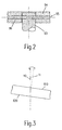
- Fig. 3 explains the conditions that arise in such a bearing can if the inner surfaces of the discs 81 and 82 are not exactly perpendicular to the bearing part 84 run.
- the axis of symmetry of the bearing part 84 forms the Axis of rotation 10 of the plain bearing.
- the inner surfaces of the disks 81 and 82 are designated 810 and 820 and intersect the axis of rotation at one of 90 ° different angles.
- the plate 94 adapts to this inclination, his Axis of symmetry 11 with the axis of rotation 10 an angle different from 0 ° 3 (for the sake of clarity, this angle is exaggerated in Fig. 3) shown; in reality it is only a fraction of 1 °).
- the surfaces 810 and 820 continually change their position in space, taking the disc 94 follows this movement, its axis of symmetry 11 with the rotation frequency precessed about the axis of rotation 10.
- the thrust bearing and the radial bearing have approximately the same outer diameter.
- the axial and radial bearing surfaces then do not occur due to different Centrifugal forces in a lubricant competition, in which they mutually Can withdraw lubricants. This is especially true for higher speeds important.
- Fig. 4 shows one Embodiment in which this is not the case and in which the disk 94 is the Surrounds shaft 91 in the middle between two radial spiral groove patterns 910.
- the pin 96 which has a threaded area 97 in the disk 94 is secured (the same is the case with the embodiment according to FIGS. 1 and 3 possible), has a spherical area in the middle, which little play in a bore in the shaft perpendicular to the axis of rotation 10 91 is located so that the plate 94 can be tilted slightly relative to the axis 91 can.
- this embodiment has the disadvantage that the axis 91st must be massive and can not be cooled via an inner bore, as with the Embodiment according to FIG. 1.
- FIG. 5 shows a section of a further embodiment of the interior Bearing body in which the tilting of the ring 94 against one (on the not Axle 91 shown in detail) shaft 98 is achieved in that the inner surfaces of the disk 94 facing the shaft 98 and those of the disk 94 facing outer surfaces of the shaft 98 like the parts of a spherical surface are shaped.
- the parts 93 and 94 form a spherical bearing that is easy Inclination of the disc 94 relative to the shaft 98 allowed.
Landscapes
- Engineering & Computer Science (AREA)
- General Engineering & Computer Science (AREA)
- Mechanical Engineering (AREA)
- Sliding-Contact Bearings (AREA)
Applications Claiming Priority (2)
| Application Number | Priority Date | Filing Date | Title |
|---|---|---|---|
| DE19733274A DE19733274A1 (de) | 1997-08-01 | 1997-08-01 | Drehanoden-Röntgenröhre mit einem Gleitlager |
| DE19733274 | 1997-08-01 |
Publications (2)
| Publication Number | Publication Date |
|---|---|
| EP0895273A1 EP0895273A1 (de) | 1999-02-03 |
| EP0895273B1 true EP0895273B1 (de) | 2004-05-19 |
Family
ID=7837674
Family Applications (1)
| Application Number | Title | Priority Date | Filing Date |
|---|---|---|---|
| EP98202503A Expired - Lifetime EP0895273B1 (de) | 1997-08-01 | 1998-07-27 | Drehanoden-Röntgenröhre mit einem Gleitlager |
Country Status (4)
| Country | Link |
|---|---|
| US (1) | US6064719A (enExample) |
| EP (1) | EP0895273B1 (enExample) |
| JP (1) | JPH1196949A (enExample) |
| DE (2) | DE19733274A1 (enExample) |
Families Citing this family (10)
| Publication number | Priority date | Publication date | Assignee | Title |
|---|---|---|---|---|
| JP4357094B2 (ja) * | 1999-08-10 | 2009-11-04 | 株式会社東芝 | 回転陽極型x線管及びそれを内蔵したx線管装置 |
| DE102007034463A1 (de) * | 2007-07-20 | 2009-01-29 | Sanofi-Aventis Deutschland Gmbh | Gleitlager und Reaktor hiermit |
| DE102009031530A1 (de) * | 2009-07-02 | 2011-01-13 | Siemens Aktiengesellschaft | Gleitlager für hohe Drehgeschwindigkeiten eines Anodentellers |
| EP2553283B1 (en) | 2010-03-31 | 2015-01-07 | Koninklijke Philips N.V. | Bearing system for a rotary anode of an x-ray tube |
| CN102834895B (zh) * | 2010-04-12 | 2015-09-16 | 皇家飞利浦电子股份有限公司 | 具有简化的径向密封的旋转阳极x射线管 |
| US8300770B2 (en) | 2010-07-13 | 2012-10-30 | Varian Medical Systems, Inc. | Liquid metal containment in an x-ray tube |
| WO2012059824A1 (en) | 2010-11-05 | 2012-05-10 | Koninklijke Philips Electronics N.V. | Hydrodynamic tumble disc bearing system |
| US8897420B1 (en) * | 2012-02-07 | 2014-11-25 | General Electric Company | Anti-fretting coating for rotor attachment joint and method of making same |
| US9972472B2 (en) * | 2014-11-10 | 2018-05-15 | General Electric Company | Welded spiral groove bearing assembly |
| US11020067B1 (en) * | 2020-02-12 | 2021-06-01 | GE Precision Healthcare LLC | Hydrodynamic bearing system and method for manufacturing the hydrodynamic bearing system |
Family Cites Families (4)
| Publication number | Priority date | Publication date | Assignee | Title |
|---|---|---|---|---|
| DE3900729A1 (de) * | 1989-01-12 | 1990-07-19 | Philips Patentverwaltung | Drehanoden-roentgenroehre mit einem gleitlager, insbesondere einem spiralrillenlager |
| EP0524673B1 (en) * | 1991-07-05 | 1997-06-11 | Koninklijke Philips Electronics N.V. | Bearing arrangement, device with a rotatable disc, and magnetic-tape apparatus |
| DE4222225A1 (de) * | 1992-07-07 | 1994-01-13 | Philips Patentverwaltung | Gleitlager für eine Drehanoden-Röntgenröhre |
| DE19502207A1 (de) * | 1995-01-25 | 1996-08-01 | Philips Patentverwaltung | Drehanoden-Röntgenröhre mit einem Gleitlager |
-
1997
- 1997-08-01 DE DE19733274A patent/DE19733274A1/de not_active Withdrawn
-
1998
- 1998-07-23 US US09/121,575 patent/US6064719A/en not_active Expired - Fee Related
- 1998-07-27 DE DE59811414T patent/DE59811414D1/de not_active Expired - Lifetime
- 1998-07-27 EP EP98202503A patent/EP0895273B1/de not_active Expired - Lifetime
- 1998-07-29 JP JP21430198A patent/JPH1196949A/ja active Pending
Also Published As
| Publication number | Publication date |
|---|---|
| DE59811414D1 (de) | 2004-06-24 |
| US6064719A (en) | 2000-05-16 |
| JPH1196949A (ja) | 1999-04-09 |
| DE19733274A1 (de) | 1999-02-04 |
| EP0895273A1 (de) | 1999-02-03 |
Similar Documents
| Publication | Publication Date | Title |
|---|---|---|
| EP0578314B1 (de) | Gleitlager für eine Drehanoden-Röntgenröhre | |
| EP0895273B1 (de) | Drehanoden-Röntgenröhre mit einem Gleitlager | |
| DE69408425T2 (de) | Planetengetriebe mit Lastverteilung | |
| DE3233753A1 (de) | Gleichlaufdrehgelenk | |
| DE69101667T2 (de) | Taumelscheibenvorrichtung mit in Nicken und Rollen ausgekuppelten Gelenken montiert für die Einstellwinkelsteuerung der Rotorblätter eines Drehflügelflugzeuges. | |
| DE69118473T3 (de) | Drehanoden-Röntgenröhre | |
| EP0256465B1 (de) | Deformationsregelwalze | |
| DE4317364A1 (de) | Universalgelenk | |
| DE3308636C2 (de) | Tripode-Gleichlaufgelenk | |
| EP1474616B1 (de) | Drehgleitlager | |
| EP0724283B1 (de) | Drehanoden-Röntgenröhre mit einem Gleitlager | |
| EP0197182B1 (de) | Konus-Schneckenmischer mit sphärischem Dichtungskörper in der Bodenöffnung | |
| DE3307845A1 (de) | Kaefig fuer radial-kugellager | |
| EP0635650A1 (de) | Kippbewegliche Laufrollenlagerung | |
| DE2840465C2 (enExample) | ||
| DE102006031156A1 (de) | Lagereinrichtung und Röntgenröhre | |
| EP0309762B1 (de) | Verstellbare Axialkolbenmaschine in Schrägscheibenbauweise | |
| DE19527649B4 (de) | Axialkolbenmaschine | |
| DE19642021B4 (de) | Hydrostatische Axialkolbenmaschine | |
| DE69932241T2 (de) | Drehlager | |
| EP0902455B1 (de) | Drehanoden-Röntgenröhre mit einem hydrodynamischen Gleitlager | |
| DE3433289C2 (enExample) | ||
| DE102008001490A1 (de) | Einstufiges Taumelradgetriebe mit Stirnverzahnung | |
| DE3800356A1 (de) | Kompressor | |
| DE102020134710B4 (de) | Zahnradgetriebe mit Taumelkörper |
Legal Events
| Date | Code | Title | Description |
|---|---|---|---|
| PUAI | Public reference made under article 153(3) epc to a published international application that has entered the european phase |
Free format text: ORIGINAL CODE: 0009012 |
|
| AK | Designated contracting states |
Kind code of ref document: A1 Designated state(s): DE FR GB NL |
|
| AX | Request for extension of the european patent |
Free format text: AL;LT;LV;MK;RO;SI |
|
| 17P | Request for examination filed |
Effective date: 19990803 |
|
| AKX | Designation fees paid |
Free format text: DE FR GB NL |
|
| RAP3 | Party data changed (applicant data changed or rights of an application transferred) |
Owner name: KONINKLIJKE PHILIPS ELECTRONICS N.V. Owner name: PHILIPS CORPORATE INTELLECTUAL PROPERTY GMBH |
|
| RAP1 | Party data changed (applicant data changed or rights of an application transferred) |
Owner name: KONINKLIJKE PHILIPS ELECTRONICS N.V. Owner name: PHILIPS CORPORATE INTELLECTUAL PROPERTY GMBH |
|
| 17Q | First examination report despatched |
Effective date: 20020924 |
|
| RAP1 | Party data changed (applicant data changed or rights of an application transferred) |
Owner name: KONINKLIJKE PHILIPS ELECTRONICS N.V. Owner name: PHILIPS INTELLECTUAL PROPERTY & STANDARDS GMBH |
|
| GRAP | Despatch of communication of intention to grant a patent |
Free format text: ORIGINAL CODE: EPIDOSNIGR1 |
|
| GRAS | Grant fee paid |
Free format text: ORIGINAL CODE: EPIDOSNIGR3 |
|
| GRAA | (expected) grant |
Free format text: ORIGINAL CODE: 0009210 |
|
| AK | Designated contracting states |
Kind code of ref document: B1 Designated state(s): DE FR GB NL |
|
| PG25 | Lapsed in a contracting state [announced via postgrant information from national office to epo] |
Ref country code: NL Free format text: LAPSE BECAUSE OF FAILURE TO SUBMIT A TRANSLATION OF THE DESCRIPTION OR TO PAY THE FEE WITHIN THE PRESCRIBED TIME-LIMIT Effective date: 20040519 Ref country code: FR Free format text: LAPSE BECAUSE OF FAILURE TO SUBMIT A TRANSLATION OF THE DESCRIPTION OR TO PAY THE FEE WITHIN THE PRESCRIBED TIME-LIMIT Effective date: 20040519 |
|
| REG | Reference to a national code |
Ref country code: GB Ref legal event code: FG4D Free format text: NOT ENGLISH |
|
| REF | Corresponds to: |
Ref document number: 59811414 Country of ref document: DE Date of ref document: 20040624 Kind code of ref document: P |
|
| GBT | Gb: translation of ep patent filed (gb section 77(6)(a)/1977) |
Effective date: 20040729 |
|
| NLV1 | Nl: lapsed or annulled due to failure to fulfill the requirements of art. 29p and 29m of the patents act | ||
| PLBE | No opposition filed within time limit |
Free format text: ORIGINAL CODE: 0009261 |
|
| STAA | Information on the status of an ep patent application or granted ep patent |
Free format text: STATUS: NO OPPOSITION FILED WITHIN TIME LIMIT |
|
| 26N | No opposition filed |
Effective date: 20050222 |
|
| EN | Fr: translation not filed | ||
| PGFP | Annual fee paid to national office [announced via postgrant information from national office to epo] |
Ref country code: GB Payment date: 20100802 Year of fee payment: 13 |
|
| PGFP | Annual fee paid to national office [announced via postgrant information from national office to epo] |
Ref country code: DE Payment date: 20100930 Year of fee payment: 13 |
|
| GBPC | Gb: european patent ceased through non-payment of renewal fee |
Effective date: 20110727 |
|
| PG25 | Lapsed in a contracting state [announced via postgrant information from national office to epo] |
Ref country code: DE Free format text: LAPSE BECAUSE OF NON-PAYMENT OF DUE FEES Effective date: 20120201 |
|
| REG | Reference to a national code |
Ref country code: DE Ref legal event code: R119 Ref document number: 59811414 Country of ref document: DE Effective date: 20120201 |
|
| PG25 | Lapsed in a contracting state [announced via postgrant information from national office to epo] |
Ref country code: GB Free format text: LAPSE BECAUSE OF NON-PAYMENT OF DUE FEES Effective date: 20110727 |