EP0893260A2 - Vorrichtung und Verfahren zum Tintenstrahldrucken mit Druckmodussteuerung - Google Patents
Vorrichtung und Verfahren zum Tintenstrahldrucken mit Druckmodussteuerung Download PDFInfo
- Publication number
- EP0893260A2 EP0893260A2 EP98202342A EP98202342A EP0893260A2 EP 0893260 A2 EP0893260 A2 EP 0893260A2 EP 98202342 A EP98202342 A EP 98202342A EP 98202342 A EP98202342 A EP 98202342A EP 0893260 A2 EP0893260 A2 EP 0893260A2
- Authority
- EP
- European Patent Office
- Prior art keywords
- waveform
- nozzle
- ink
- providing
- calibrator
- Prior art date
- Legal status (The legal status is an assumption and is not a legal conclusion. Google has not performed a legal analysis and makes no representation as to the accuracy of the status listed.)
- Withdrawn
Links
Images


Classifications
-
- B—PERFORMING OPERATIONS; TRANSPORTING
- B41—PRINTING; LINING MACHINES; TYPEWRITERS; STAMPS
- B41J—TYPEWRITERS; SELECTIVE PRINTING MECHANISMS, i.e. MECHANISMS PRINTING OTHERWISE THAN FROM A FORME; CORRECTION OF TYPOGRAPHICAL ERRORS
- B41J2/00—Typewriters or selective printing mechanisms characterised by the printing or marking process for which they are designed
- B41J2/005—Typewriters or selective printing mechanisms characterised by the printing or marking process for which they are designed characterised by bringing liquid or particles selectively into contact with a printing material
- B41J2/01—Ink jet
- B41J2/015—Ink jet characterised by the jet generation process
- B41J2/04—Ink jet characterised by the jet generation process generating single droplets or particles on demand
- B41J2/045—Ink jet characterised by the jet generation process generating single droplets or particles on demand by pressure, e.g. electromechanical transducers
- B41J2/04501—Control methods or devices therefor, e.g. driver circuits, control circuits
- B41J2/04551—Control methods or devices therefor, e.g. driver circuits, control circuits using several operating modes
-
- B—PERFORMING OPERATIONS; TRANSPORTING
- B41—PRINTING; LINING MACHINES; TYPEWRITERS; STAMPS
- B41J—TYPEWRITERS; SELECTIVE PRINTING MECHANISMS, i.e. MECHANISMS PRINTING OTHERWISE THAN FROM A FORME; CORRECTION OF TYPOGRAPHICAL ERRORS
- B41J2/00—Typewriters or selective printing mechanisms characterised by the printing or marking process for which they are designed
- B41J2/005—Typewriters or selective printing mechanisms characterised by the printing or marking process for which they are designed characterised by bringing liquid or particles selectively into contact with a printing material
- B41J2/01—Ink jet
- B41J2/015—Ink jet characterised by the jet generation process
- B41J2/04—Ink jet characterised by the jet generation process generating single droplets or particles on demand
- B41J2/045—Ink jet characterised by the jet generation process generating single droplets or particles on demand by pressure, e.g. electromechanical transducers
- B41J2/04501—Control methods or devices therefor, e.g. driver circuits, control circuits
- B41J2/0458—Control methods or devices therefor, e.g. driver circuits, control circuits controlling heads based on heating elements forming bubbles
-
- B—PERFORMING OPERATIONS; TRANSPORTING
- B41—PRINTING; LINING MACHINES; TYPEWRITERS; STAMPS
- B41J—TYPEWRITERS; SELECTIVE PRINTING MECHANISMS, i.e. MECHANISMS PRINTING OTHERWISE THAN FROM A FORME; CORRECTION OF TYPOGRAPHICAL ERRORS
- B41J2/00—Typewriters or selective printing mechanisms characterised by the printing or marking process for which they are designed
- B41J2/005—Typewriters or selective printing mechanisms characterised by the printing or marking process for which they are designed characterised by bringing liquid or particles selectively into contact with a printing material
- B41J2/01—Ink jet
- B41J2/015—Ink jet characterised by the jet generation process
- B41J2/04—Ink jet characterised by the jet generation process generating single droplets or particles on demand
- B41J2/045—Ink jet characterised by the jet generation process generating single droplets or particles on demand by pressure, e.g. electromechanical transducers
- B41J2/04501—Control methods or devices therefor, e.g. driver circuits, control circuits
- B41J2/04588—Control methods or devices therefor, e.g. driver circuits, control circuits using a specific waveform
-
- B—PERFORMING OPERATIONS; TRANSPORTING
- B41—PRINTING; LINING MACHINES; TYPEWRITERS; STAMPS
- B41J—TYPEWRITERS; SELECTIVE PRINTING MECHANISMS, i.e. MECHANISMS PRINTING OTHERWISE THAN FROM A FORME; CORRECTION OF TYPOGRAPHICAL ERRORS
- B41J2/00—Typewriters or selective printing mechanisms characterised by the printing or marking process for which they are designed
- B41J2/005—Typewriters or selective printing mechanisms characterised by the printing or marking process for which they are designed characterised by bringing liquid or particles selectively into contact with a printing material
- B41J2/01—Ink jet
- B41J2/015—Ink jet characterised by the jet generation process
- B41J2/04—Ink jet characterised by the jet generation process generating single droplets or particles on demand
- B41J2/045—Ink jet characterised by the jet generation process generating single droplets or particles on demand by pressure, e.g. electromechanical transducers
- B41J2/04501—Control methods or devices therefor, e.g. driver circuits, control circuits
- B41J2/0459—Height of the driving signal being adjusted
-
- B—PERFORMING OPERATIONS; TRANSPORTING
- B41—PRINTING; LINING MACHINES; TYPEWRITERS; STAMPS
- B41J—TYPEWRITERS; SELECTIVE PRINTING MECHANISMS, i.e. MECHANISMS PRINTING OTHERWISE THAN FROM A FORME; CORRECTION OF TYPOGRAPHICAL ERRORS
- B41J2/00—Typewriters or selective printing mechanisms characterised by the printing or marking process for which they are designed
- B41J2/005—Typewriters or selective printing mechanisms characterised by the printing or marking process for which they are designed characterised by bringing liquid or particles selectively into contact with a printing material
- B41J2/01—Ink jet
- B41J2/015—Ink jet characterised by the jet generation process
- B41J2/04—Ink jet characterised by the jet generation process generating single droplets or particles on demand
- B41J2/045—Ink jet characterised by the jet generation process generating single droplets or particles on demand by pressure, e.g. electromechanical transducers
- B41J2/04501—Control methods or devices therefor, e.g. driver circuits, control circuits
- B41J2/04591—Width of the driving signal being adjusted
-
- B—PERFORMING OPERATIONS; TRANSPORTING
- B41—PRINTING; LINING MACHINES; TYPEWRITERS; STAMPS
- B41J—TYPEWRITERS; SELECTIVE PRINTING MECHANISMS, i.e. MECHANISMS PRINTING OTHERWISE THAN FROM A FORME; CORRECTION OF TYPOGRAPHICAL ERRORS
- B41J2/00—Typewriters or selective printing mechanisms characterised by the printing or marking process for which they are designed
- B41J2/005—Typewriters or selective printing mechanisms characterised by the printing or marking process for which they are designed characterised by bringing liquid or particles selectively into contact with a printing material
- B41J2/01—Ink jet
- B41J2/015—Ink jet characterised by the jet generation process
- B41J2/04—Ink jet characterised by the jet generation process generating single droplets or particles on demand
- B41J2/045—Ink jet characterised by the jet generation process generating single droplets or particles on demand by pressure, e.g. electromechanical transducers
- B41J2/04501—Control methods or devices therefor, e.g. driver circuits, control circuits
- B41J2/04593—Dot-size modulation by changing the size of the drop
-
- B—PERFORMING OPERATIONS; TRANSPORTING
- B41—PRINTING; LINING MACHINES; TYPEWRITERS; STAMPS
- B41J—TYPEWRITERS; SELECTIVE PRINTING MECHANISMS, i.e. MECHANISMS PRINTING OTHERWISE THAN FROM A FORME; CORRECTION OF TYPOGRAPHICAL ERRORS
- B41J2/00—Typewriters or selective printing mechanisms characterised by the printing or marking process for which they are designed
- B41J2/005—Typewriters or selective printing mechanisms characterised by the printing or marking process for which they are designed characterised by bringing liquid or particles selectively into contact with a printing material
- B41J2/01—Ink jet
- B41J2/015—Ink jet characterised by the jet generation process
- B41J2/04—Ink jet characterised by the jet generation process generating single droplets or particles on demand
- B41J2/045—Ink jet characterised by the jet generation process generating single droplets or particles on demand by pressure, e.g. electromechanical transducers
- B41J2/04501—Control methods or devices therefor, e.g. driver circuits, control circuits
- B41J2/04595—Dot-size modulation by changing the number of drops per dot
Definitions
- the present invention generally relates to digital image printing apparatus and methods, and more particularly to an ink jet printing apparatus and method accommodating printing mode control.
- An ink jet printer produces images on a receiver medium by ejecting ink droplets onto the receiver medium in an imagewise fashion.
- the advantages of non-impact, low-noise, low-energy use, low cost and the capability to print on plain paper are largely responsible for the wide acceptance of ink jet printers in the marketplace.
- the quality of images printed by ink jet printers is related to the absorption of inks into an ink receiver which can be plain paper, coated paper, transparent film and the like.
- Ink absorption capability of the ink receiver is characterized by properties of the receiver, such as the amount and the rate of the ink absorption. These properties are determined by the type of receiver. For example, it may be desirable to select specialty receivers coated with ink absorption layers which can absorb more ink at a faster rate (that is, shorter "drying" time) than plain paper.
- a problem associated with ink jet printing is excessive laydown of inks on the ink receiver. That is, when inks are placed on the receiver at an amount or rate higher than the receiver can accept, image defects can occur. For example, image artifacts can occur when neighboring ink pixels come in contact with each other and coalesce. This type of image artifact is commonly referred as "ink beading". Coalescence of ink pixels on the receiver causes inks to diffuse or flow among ink pixels and results in a non-uniform or mottled appearance of the printed image. This ink diffusion problem is most visible at the boundaries of printed areas comprising different colors, where the ink of one color diffuses into the adjacent area of a different color ink to form a finger-shaped pattern. This latter image defect is commonly referred to as "color bleeding".
- US-A- 4,748,453 discloses a technique involving printing an image area with at least two passes. In each pass, the ink pixels are printed in a checkerboard pattern of diagonally adjacent pixels. The final image is formed by the sum of the complimentary checkerboard patterns in different printing passes.
- a disadvantage of this technique is the increased printing time caused by multiple printing passes.
- an object of the present invention is to provide an ink jet printing apparatus and method accommodating printing mode control for printing multiple-density levels on a receiver medium in a manner solving the problems of ink beading and color bleeding while avoiding excessive printing time and excessive ink laydown.
- the present invention resides in an ink jet printing apparatus capable of receiving an input image having a plurality of pixels comprising of a printhead, at least one nozzle integrally attached to said printhead, said nozzle capable of ejecting an ink droplet, a waveform generator connected to said printhead for generating an electronic waveform to be supplied to said nozzle for ejecting the ink droplet, the waveform defined by a plurality of pulses, a printer performance look-up table associated with said waveform generator for storing at least one electronic waveform serial number assigned to the corresponding waveform, and a calibrator associated with said printer performance look-up table and said waveform generator for selecting electronic waveform serial numbers according to a printer mode.
- a feature of the present invention is the provision of an ink depletion method that reduces ink laydown on an ink receiver by varying the volume of the ejected ink droplets.
- Another feature of the present invention is the provision of look-up tables relating printed optical densities to electronic waveforms which drive a print head belonging to the printer, the electronic waveforms being associated with electronic waveform numbers.
- Still another feature of the present invention is the provision of a first calibrator for calibrating an input image file to pixel values associated with the electronic waveform numbers.
- Yet another feature of the present invention is the provision of a second calibrator that calibrates the calibrated image file of pixel values according to the printing mode input by the user in order to avoid excessive ink laydown.
- An advantage of the present invention is that ink depletion is accomplished without increasing printing time.
- Another advantage of the present invention is that ink depletion is achieved without reducing spatial resolution in the printed image.
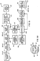
- an ink jet printer apparatus includes an electronic memory 20 having a digital image file I(x, y) stored therein.
- image file I(x, y) the letters "x" and “y” designate column and row numbers, respectively, the combination of which define pixel locations in an image plane. More specifically, a plurality of color pixels with pixel values at each "x" and "y” location correspond to desired color densities (that is, "aim densities") when printed on a receiver medium 30.
- Image file I(x, y) may be generated by a computer or, alternatively, provided as an input generated from a magnetic disk, compact disk, memory card, magnetic tape, digital camera, print scanner, film scanner, or the like. Moreover, image file I(x, y) may be provided in any suitable format well known in the art, such as page-description language or bitmap format.
- image processor 40 electrically connected to electronic memory 20 is an image processor 40, which processes image file I(x, y). That is, image processor 40 is capable of performing any one of several desired operations on image file I(x, y). These operations may be, for example, decoding, decompression, rotation, resizing, coordinate transformation, mirror-image transformation, tone scale adjustment, color management, in addition to other desired operations.
- Image processor 40 generates an output image file I p (x, y), which includes a plurality of pixel values having color code values for ink pixels produced by a plurality of ink delivery nozzles 45 (only one of which is shown) integrally connected to an ink jet print head 50. Each nozzle 45 has an ink chamber 46 for ejecting an ink droplet 47 therefrom.
- PLUT 60 provides an electronic waveform, generally referred to as 80, comprising a group or series of "square" pulses, generally referred to as 90 (only three of which are shown), for driving print head 50.
- Electronic waveform 80 is characterized by waveform parameters, such as number of pulses, pulse widths (that is, W 1 , W 2 , W 3 ...), voltage pulse amplitudes (that is, A 1 , A 2 , A 3 %), and delay time intervals (that is, S 1-2 , S 2-3 ”) between pulses 90.
- Predetermined values of pulse amplitudes, widths and delay time intervals between pulses are selected depending on a desired mode of operation of printhead 50, as disclosed more fully hereinbelow.
- a desired mode of operation for a piezoelectric ink jet print head 50 may be that frequencies of pulses 90 are reinforced by the resonance frequencies of ink chamber 46, so that the energy cost for ink ejection is minimized.
- Predetermining the parametric values of the number of pulses, pulse amplitude, pulse width and time delay between pulses results in discrete ink droplet volumes that in turn are modulatable by electronic waveform 80.
- square pulses 90 are only an example of many possible electronic waveforms usable for driving print head 50.
- Alternative electronic waveforms usable with the present invention include, for example, triangular, trapezoidal, and sinusoidal waveforms, either in unipolar or bi-polar voltages.
- electronic waveform 80 may be fully or partially continuous without one or more delay time intervals (S 1-2 , S 2-3 ).
- Such waveforms have parameters analogous to the parameters of square wave 90.
- a continuous sinusoidal waveform can be characterized by the period and the amplitude of each cycle or each half cycle plus a constant voltage.
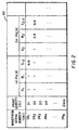
- PLUT 60 also includes the previously mentioned parameters of number of pulses, pulse widths (W 1 ,W 2 , W 3 ...), pulse amplitudes (A 1 , A 2 , A 3 %), and delay time intervals between the pulses (S 1-2 , S 2-3 ).
- optical densities D 1 , D 2 , D 3 optical densities D 1 , D 2 , D 3 ...
- optical density refers to reflective or transmittance optical density as measured by a densitometer (not shown) set in the well-known Status "A” or Status "M” mode, respectively.
- the reflective and transmittance optical densities are measured from reflective (for example, coated paper) or transmittance (for example, transparent film) ink receivers, respectively.
- the density D i is measured from a uniform density patch of a test image (not shown), which is printed by driving the nozzles with the electronic waveform corresponding to the waveform serial number SN i .
- N is the total number of electronic waveforms in PLUT 60 and "D max " is the maximum achievable optical density.
- D max is the maximum achievable optical density.
- the series of electronic waveforms SN i listed in PLUT 60 are only a subset of all possible electronic waveforms capable of driving ink jet print head 50. However, when printing with all possible electronic waveforms, many electronic waveforms result in equal or similar optical densities D i . Only suitable ones of these waveforms are selected and listed as the electronic waveforms in PLUT 60. Such a selection is made by minimizing a gap or difference between any two optical densities D i and the corresponding two consecutive waveform serial numbers SN i . Minimizing such gaps minimize quantization errors and thereby arrive at suitable waveforms.
- printer performance curve 70 formed by plotting optical density as a function of waveform index number IN.
- the N electronic waveforms in PLUT 60 are used first to print an image comprising uniform-density patches (not shown) from which optical densities are obtained for each waveform serial number SN i which corresponds to a unique waveform.
- the plurality of "x" symbols in Fig. 4 represent data points obtained from PLUT 60 corresponding to the SN's in PLUT 60.
- the data points "x" are interpolated by techniques well known in the art to produce a continuous curve for expressing IN as a continuous variable.
- waveform serial number SN i describes the discrete optical density levels (that is, tones) which ink jet printer apparatus 10 is capable of producing.
- the total level N ranges from 2 to 64 available levels, that is, 1 to 6 bit depth.
- the index number waveform IN represents substantially continuous tone. This is, there should be higher than 8 bit levels (2 8 ), for example, 10 - 12 bits, used to describe the waveform index numbers IN.
- image file I p (x, y) is calibrated by a first image calibrator 95.
- I p (x, y) includes color code pixel values for each of the yellow, magenta, cyan, and black color planes. Each color code pixel value is associated with a desired optical density for that color, as defined by the input image file I(x, y).
- the calibration performed by first image calibrator 95 converts each color pixel value to a waveform index number IN using (a) the aim density at that pixel for that color and (b) the printer performance curve 70. This calibration process results in an image file IN(x, y) with pixel values described by waveform index number IN.
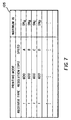
- the calibrated image file IN(x, y) is next calibrated in a second image calibrator 100 according to a printer mode selector 105 selected from a printer M ode L ook- U p T able (MLUT) 107 that receives input from the printer user by means of an input printer mode selector 105.
- MLUT 107 An example of MLUT 107 is shown in FIG. 7.
- the printing mode 107 includes parameters such as the receiver type (for example, in the form of type "1", “2"... and so forth) for receiver medium 30, printing resolution (for example, in the form of 300, 600, 1200 dots per inch), and printing speed, or other desired printing mode parameters.
- Second image calibrator 100 adjusts the electronic waveforms to avoid excessive ink laydown for the input printing mode.
- An example of how image calibrator 72 adjusts ink laydown as a function of printing speed is described hereinbelow. However, it is understood that the following description is by way of example only because various techniques within the scope of the present invention may be used to adjust ink laydown as a function of printing speed.
- calibration by second image calibrator 100 can readily be adapted to other printing modes in order to accommodate desired printing image resolution and ink receiver type.
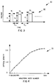
- FIG. 5 there is shown an exemplary graph of maximum ink laydown on ink receiver 30 as a function of the printing speed.
- the maximum ink laydown is the maximum amount of ink laydown beyond which ink beading or coalescence appears on ink receiver 30.
- the printing speed is defined herein to mean the transport speed of the print head 50 relative to ink receiver 30.
- the printing mode in this example uses the four ink colors yellow, magenta, and cyan (designated by the letters Y, M, and C, respectively). An additional black color can be added.
- the printing resolution and receiver type in this example are fixed.
- maximum ink laydowns at different printing speeds are empirically obtained by varying ink laydown at a predetermined fixed printing speed.
- the previously mentioned test image (not shown) includes uniform density patches printed by the same electronic waveform.
- the ink laydown value at which ink beading appears represents the maximum ink laydown at that printing speed.
- the maximum ink laydown decreases as the printing speed increases. For example, conditions from point "A" to point “D” represent increased printing speeds and decreased maximum ink laydowns. This phenomena of decreased ink laydown as printing speed increases arises from competition between the rate of ink absorption by the ink receiver 30 and the firing rate of ink droplets 47 from printhead nozzles 45.
- An increase in printing speed decreases the time interval between sequential ink droplets 47. This requires the amount of the printed ink to decrease in order to avoid coalescence between printed ink pixels.
- Fig. 6 is a graph showing ink droplet volume as a function of waveform index number.
- Ink droplets 47 are ejected from the nozzles 45 when print head 50 is driven by electronic waveforms 80 corresponding to respective waveform serial numbers shown on the horizontal axis of Figure 6.
- This ink droplet volume ejected from ink nozzles can be measured by a number of methods known in the art. For example, ink droplet volume can be measured by the light scattering technique disclosed in US-A- 5,621,524.
- FIGs. 5 and 6 it may be understood that the functional dependence of the optical density and the ink droplet volumes in Figures 4 and 6 are consistent. That is, both Figs. 5 and 6 show that increased ink droplet volumes lead to increased print optical densities.
- the printing conditions point "A" to point “D” in Figure 5 have increased printing speeds, thus requiring decreased maximum ink laydowns.
- the decreased maximum ink laydowns from point "A" to point “D” are achieved by decreased ink droplet volumes as shown in Figure 6.
- all the pixels are obtained without increasing the number of printing passes. Preferably, a single printing pass is used for maximum printing efficiency.
- the maximum ink laydown at printing conditions from point “A” to point “D” are printed by ink droplets 47 driven by electronic waveforms corresponding to waveform serial numbers SN A , SN B , SN C and SN D .
- the waveform serial numbers SN A , SN B , SN C and SN D therefore represent the maximum waveform serial numbers available at each printing condition from point "A" to point "D".
- MLUT 107 is obtained from the performance data shown in Figs. 5 and 6.
- the purpose of the second image calibrator 100 is to convert calibrated image file IN(x, y) with pixel values in the range of [0, SN N ] shown in PLUT 60 of Figure 2, to image file IN B (x, y) with pixel values in the ranges as required by the input printing modes shown in FIG. 7. For example, for printing speeds from point "A" to point "D,' for receiver type "1" and at 600 dpi printing resolution shown in FIG.
- the pixel values in IN B (x, y) are required to be in the ranges of [0, SN A ], [0, SN B ], [0, SN C ] and [0, SN D ], and so forth
- the new pixel values in IN B (x, y) in second image calibrator 100 linearly scale the pixel values (that is IN values) in IN(x, y) by a factor of SN A / SN N for printing condition point "A" (or SN B / SN N , SN C /SN N , and SN D / SN N for printing conditions from point "B" to point "D", respectively). It is understood that many other linear or non-linear formulations can be used in second image calibrator 100.
- image halftoning unit 110 is next used to minimize image artifacts.
- image halftoning refers to the image processing technique which creates the appearance of intermediate tones by the spatial modulation of two tones, for example, black and white, or multiple levels of tones, such as black, white and gray levels.
- Halftoning improves image quality by minimizing image artifacts such as contouring and noise, both of which result from printing with a finite number of tone levels.
- image halftoning is often referred to as multiple level halftoning, or multi-level halftoning, or simply multi-toning.
- image halftoning includes bi-level and multiple level halftoning, as well.
- calibrated image file IN B (x, y) is input to image halftoning unit 110.
- Calibrated image file IN B (x, y) comprises a plurality of pixels with each pixel described by waveform index number IN for each color in a range as required by the selected printing mode and as calibrated in second image calibrator 100.
- the waveform index numbers IN are described in more than 8 bit per pixel per color.
- the total number of waveform serial numbers, N, corresponding to different optical densities is in the range 2 1 to 2 6 , which is much smaller than the total number of waveform index numbers IN.
- the function of image halftoning unit 110 is to quantify the calibrated image file IN B (x, y) with pixel values described by the waveform index number IN to an image file SN(x, y) with pixel values described by the waveform serial numbers SN i . This is accomplished by spatially modulating adjacent waveform serial numbers SN i (that is, image halftoning). These waveform serial numbers SN's are stored in printer performance PLUT 60.
- a halftoned image file SN(x, y) is next sent to a controller 200.
- Controller 200 performs the function of controlling the correct waveforms to be generated for corresponding pixels. Controller 200 accomplishes this function by (a) receiving a waveform serial number SN at each pixel and each color of the halftoned image file SN(x, y); (b) looking up the waveform parameters corresponding to the waveform serial number SN at that pixel and color of SN(x, y) using PLUT 60; (c) sending the waveform parameters to waveform generator 210; and (d) selecting the correct nozzle 45 corresponding to that color and the pixel by sending signals to a nozzle selector 220 that is connected to waveform generator 210.
- Waveform generator 210 generates the correct waveforms in response to the previously mentioned waveform parameters provided by controller 200. This provides the proper waveforms to actuate an electromechanical transducer 230 or a heat generating element 240 that in turn eject droplets 47 from the appropriate ink nozzles 45 in the print head 50. That is, ink jet print head 50 may be a piezo-electric ink jet printhead as shown in Fig. 1a.
- the electromechanical transducer 230 can comprise piezo-electric material, such as PZT.
- ink jet printhead 50 may be a thermal ink jet printhead comprising a heat generating element 240 disposed in at least one nozzle 45 for generating thermal energy in response to electronic waveforms for ejecting ink droplets 47 from nozzle 45, as shown in Fig. 1b.
- the waveform generator 210 can include an electronic circuit (not shown) for producing the correct digital waveforms in combination with a digital-to-analog converter (not shown), and amplifiers (also not shown). Image-wise activation and ink ejection of ink droplets 47 reproduces the input digital image on receiver 30. Since the electronic waveforms that drive ink delivery nozzles 45 are calibrated by second calibrator 72 for each printing condition, excessive ink laydown and related image defects are avoided.
- An advantage of the present invention is that the ink laydown is reduced without increasing printing time or reducing spatial resolution in printed images. This is accomplished by varying the ink droplet volumes ejected from the ink delivery nozzles 45.
- Printer apparatus 10 neither increases the number of printing passes with a subset of pixels printed in each pass nor eliminates printed pixels as in the prior art.
- the present invention is compatible with an ink-jet apparatus using inks of different densities for each color.
- the present invention can also incorporate printing modes such as depositing a plurality of ink droplets at each image location on a receiver medium in one or more passes. Therefore, what is provided is an ink jet printing apparatus and method accommodating printing mode control for printing variable density levels on a receiver medium in a manner solving the problems of ink beading and color bleeding while avoiding excessive printing time and excessive ink laydown.
Landscapes
- Ink Jet (AREA)
- Particle Formation And Scattering Control In Inkjet Printers (AREA)
- Fax Reproducing Arrangements (AREA)
- Ink Jet Recording Methods And Recording Media Thereof (AREA)
Applications Claiming Priority (2)
| Application Number | Priority Date | Filing Date | Title |
|---|---|---|---|
| US899616 | 1992-06-15 | ||
| US08/899,616 US5975672A (en) | 1997-07-24 | 1997-07-24 | Ink jet printing apparatus and method accommodating printing mode control |
Publications (2)
| Publication Number | Publication Date |
|---|---|
| EP0893260A2 true EP0893260A2 (de) | 1999-01-27 |
| EP0893260A3 EP0893260A3 (de) | 1999-12-15 |
Family
ID=25411297
Family Applications (1)
| Application Number | Title | Priority Date | Filing Date |
|---|---|---|---|
| EP98202342A Withdrawn EP0893260A3 (de) | 1997-07-24 | 1998-07-13 | Vorrichtung und Verfahren zum Tintenstrahldrucken mit Druckmodussteuerung |
Country Status (4)
| Country | Link |
|---|---|
| US (1) | US5975672A (de) |
| EP (1) | EP0893260A3 (de) |
| JP (1) | JPH1177993A (de) |
| KR (1) | KR19990014017A (de) |
Cited By (6)
| Publication number | Priority date | Publication date | Assignee | Title |
|---|---|---|---|---|
| EP0902587A3 (de) * | 1997-09-11 | 2000-03-22 | Eastman Kodak Company | Tintenstrahldruckvorrichtung und -verfahren mit Synchronisierung der elektronischen Wellenformen zum Drucken variabler Grautonbilder ohne Artefakte |
| EP1088662A3 (de) * | 1999-09-30 | 2001-09-26 | Seiko Epson Corporation | Flüssigkeitsstrahlvorrichtung |
| US9781307B2 (en) | 2014-11-14 | 2017-10-03 | Sawgrass Technologies, Inc. | Networked digital imaging customization |
| US10419644B2 (en) | 2014-11-14 | 2019-09-17 | Sawgrass Technologies, Inc. | Digital image processing network |
| US10827097B2 (en) | 2015-11-02 | 2020-11-03 | Sawgrass Technologies, Inc. | Product imaging |
| US10827098B2 (en) | 2015-11-02 | 2020-11-03 | Sawgrass Technologies, Inc. | Custom product imaging method |
Families Citing this family (25)
| Publication number | Priority date | Publication date | Assignee | Title |
|---|---|---|---|---|
| US6352328B1 (en) * | 1997-07-24 | 2002-03-05 | Eastman Kodak Company | Digital ink jet printing apparatus and method |
| US6322208B1 (en) * | 1998-08-12 | 2001-11-27 | Eastman Kodak Company | Treatment for improving properties of ink images |
| US6547352B1 (en) * | 1999-06-25 | 2003-04-15 | Matsushita Electric Industrial Co., Ltd. | Ink jet recording device |
| ATE331624T1 (de) * | 2000-01-25 | 2006-07-15 | Seiko Epson Corp | Tintenstrahlaufzeichnungsvorrichtung, verfahren zu ihrer steuerung und medium worauf das verfahren aufgezeichnet ist |
| US7084996B2 (en) * | 2000-07-04 | 2006-08-01 | Brother Kogyo Kabushiki Kaisha | Recording device |
| GB0105067D0 (en) * | 2001-03-01 | 2001-04-18 | Zipher Ltd | Improvements in printing |
| US7016082B2 (en) * | 2001-07-05 | 2006-03-21 | Kodak Polychrome Graphics, Llc | Halftone dot thinning |
| US6913345B2 (en) * | 2003-03-21 | 2005-07-05 | Lexmark International, Inc. | Method and apparatus for firing nozzles in an ink jet printer |
| US8251471B2 (en) * | 2003-08-18 | 2012-08-28 | Fujifilm Dimatix, Inc. | Individual jet voltage trimming circuitry |
| US8068245B2 (en) | 2004-10-15 | 2011-11-29 | Fujifilm Dimatix, Inc. | Printing device communication protocol |
| US7911625B2 (en) * | 2004-10-15 | 2011-03-22 | Fujifilm Dimatrix, Inc. | Printing system software architecture |
| US7722147B2 (en) | 2004-10-15 | 2010-05-25 | Fujifilm Dimatix, Inc. | Printing system architecture |
| US7907298B2 (en) | 2004-10-15 | 2011-03-15 | Fujifilm Dimatix, Inc. | Data pump for printing |
| US8085428B2 (en) * | 2004-10-15 | 2011-12-27 | Fujifilm Dimatix, Inc. | Print systems and techniques |
| US8199342B2 (en) | 2004-10-29 | 2012-06-12 | Fujifilm Dimatix, Inc. | Tailoring image data packets to properties of print heads |
| US7234788B2 (en) * | 2004-11-03 | 2007-06-26 | Dimatix, Inc. | Individual voltage trimming with waveforms |
| US7556327B2 (en) * | 2004-11-05 | 2009-07-07 | Fujifilm Dimatix, Inc. | Charge leakage prevention for inkjet printing |
| US8199385B2 (en) * | 2007-02-15 | 2012-06-12 | Samsung Electronics Co., Ltd. | Image forming apparatus to save toner and method to control the same |
| EP2296906B1 (de) | 2008-06-06 | 2016-07-20 | Fujifilm Dimatix, Inc. | Erfassung von objekten für das drucken |
| WO2011159306A1 (en) * | 2010-06-17 | 2011-12-22 | Hewlett-Packard Development Company, L.P. | Polyurethane-containing inkjet ink |
| JP5736676B2 (ja) * | 2010-06-24 | 2015-06-17 | セイコーエプソン株式会社 | 液体噴射装置、及び、液体噴射装置の制御方法 |
| US9889649B2 (en) * | 2012-01-31 | 2018-02-13 | Canon Kabushiki Kaisha | Printing control device, printing control method, and storage medium |
| CN104029510B (zh) * | 2013-03-08 | 2016-08-03 | 北大方正集团有限公司 | 喷墨印刷浓度修正方法、修正装置及喷墨印刷方法、设备 |
| US9718269B2 (en) * | 2015-06-04 | 2017-08-01 | Electronics For Imaging, Inc. | Multi-waveform inkjet nozzle correction |
| CN106585150B (zh) * | 2016-12-10 | 2018-11-27 | 广东凯文印刷有限公司 | 在线喷印方法 |
Citations (2)
| Publication number | Priority date | Publication date | Assignee | Title |
|---|---|---|---|---|
| US4748453A (en) | 1987-07-21 | 1988-05-31 | Xerox Corporation | Spot deposition for liquid ink printing |
| US5621524A (en) | 1994-07-14 | 1997-04-15 | Hitachi Koki Co., Ltd. | Method for testing ink-jet recording heads |
Family Cites Families (13)
| Publication number | Priority date | Publication date | Assignee | Title |
|---|---|---|---|---|
| US4521786A (en) * | 1982-09-20 | 1985-06-04 | Xerox Corporation | Programmable driver/controller for ink jet printheads |
| US4617580A (en) * | 1983-08-26 | 1986-10-14 | Canon Kabushiki Kaisha | Apparatus for recording on different types of mediums |
| US5617123A (en) * | 1987-05-20 | 1997-04-01 | Canon Kabushiki Kaisha | Image processing method utilizing multiple binarizing and recording agent depositing steps |
| US5012257A (en) * | 1990-03-16 | 1991-04-30 | Hewlett-Packard Company | Ink jet color graphics printing |
| EP0670224B1 (de) * | 1990-04-20 | 2001-12-12 | Canon Kabushiki Kaisha | Vielfarbendruckgerät |
| US5321427A (en) * | 1992-06-03 | 1994-06-14 | Eastman Kodak Company | Print head modulator |
| US5633662A (en) * | 1992-08-05 | 1997-05-27 | Hewlett-Packard Company | Ink limiting in ink jet printing systems |
| US5557304A (en) * | 1993-05-10 | 1996-09-17 | Compaq Computer Corporation | Spot size modulatable ink jet printhead |
| US5495270A (en) * | 1993-07-30 | 1996-02-27 | Tektronix, Inc. | Method and apparatus for producing dot size modulated ink jet printing |
| JP3503656B2 (ja) * | 1993-10-05 | 2004-03-08 | セイコーエプソン株式会社 | インクジェットヘッドの駆動装置 |
| US5602572A (en) * | 1994-08-25 | 1997-02-11 | Minnesota Mining And Manufacturing Company | Thinned halftone dot patterns for inkjet printing |
| JPH0911463A (ja) * | 1995-06-28 | 1997-01-14 | Fuji Xerox Co Ltd | インクジェット記録装置、インクジェット記録装置の駆動装置、インクジェット記録方法 |
| AU4155097A (en) * | 1996-08-27 | 1998-03-19 | Topaz Technologies, Inc. | Inkjet print head for producing variable volume droplets of ink |
-
1997
- 1997-07-24 US US08/899,616 patent/US5975672A/en not_active Expired - Lifetime
-
1998
- 1998-07-07 JP JP10191437A patent/JPH1177993A/ja active Pending
- 1998-07-13 EP EP98202342A patent/EP0893260A3/de not_active Withdrawn
- 1998-07-21 KR KR1019980029234A patent/KR19990014017A/ko not_active Application Discontinuation
Patent Citations (2)
| Publication number | Priority date | Publication date | Assignee | Title |
|---|---|---|---|---|
| US4748453A (en) | 1987-07-21 | 1988-05-31 | Xerox Corporation | Spot deposition for liquid ink printing |
| US5621524A (en) | 1994-07-14 | 1997-04-15 | Hitachi Koki Co., Ltd. | Method for testing ink-jet recording heads |
Cited By (13)
| Publication number | Priority date | Publication date | Assignee | Title |
|---|---|---|---|---|
| EP0902587A3 (de) * | 1997-09-11 | 2000-03-22 | Eastman Kodak Company | Tintenstrahldruckvorrichtung und -verfahren mit Synchronisierung der elektronischen Wellenformen zum Drucken variabler Grautonbilder ohne Artefakte |
| US6102513A (en) * | 1997-09-11 | 2000-08-15 | Eastman Kodak Company | Ink jet printing apparatus and method using timing control of electronic waveforms for variable gray scale printing without artifacts |
| EP1088662A3 (de) * | 1999-09-30 | 2001-09-26 | Seiko Epson Corporation | Flüssigkeitsstrahlvorrichtung |
| US6517176B1 (en) | 1999-09-30 | 2003-02-11 | Seiko Epson Corporation | Liquid jetting apparatus |
| US6572210B2 (en) | 1999-09-30 | 2003-06-03 | Seiko Epson Corporation | Liquid jetting apparatus |
| EP2374620A1 (de) * | 1999-09-30 | 2011-10-12 | Seiko Epson Corporation | Flüssigkeitsausstoßvorrichtung |
| US9781307B2 (en) | 2014-11-14 | 2017-10-03 | Sawgrass Technologies, Inc. | Networked digital imaging customization |
| US10075619B2 (en) | 2014-11-14 | 2018-09-11 | Sawgrass Technologies, Inc. | Networked digital imaging customization |
| US10419644B2 (en) | 2014-11-14 | 2019-09-17 | Sawgrass Technologies, Inc. | Digital image processing network |
| US10587777B2 (en) | 2014-11-14 | 2020-03-10 | Sawgrass Technologies, Inc. | Digital image processing network |
| US10827097B2 (en) | 2015-11-02 | 2020-11-03 | Sawgrass Technologies, Inc. | Product imaging |
| US10827098B2 (en) | 2015-11-02 | 2020-11-03 | Sawgrass Technologies, Inc. | Custom product imaging method |
| US11503187B2 (en) | 2015-11-02 | 2022-11-15 | Sawgrass Technologies, Inc. | Custom product imaging method |
Also Published As
| Publication number | Publication date |
|---|---|
| EP0893260A3 (de) | 1999-12-15 |
| JPH1177993A (ja) | 1999-03-23 |
| KR19990014017A (ko) | 1999-02-25 |
| US5975672A (en) | 1999-11-02 |
Similar Documents
| Publication | Publication Date | Title |
|---|---|---|
| US5975672A (en) | Ink jet printing apparatus and method accommodating printing mode control | |
| US6102513A (en) | Ink jet printing apparatus and method using timing control of electronic waveforms for variable gray scale printing without artifacts | |
| EP0931663B1 (de) | Tintenstrahldruckapparat und Verfahren zum Tintentropfchenpositionieren mit verbesserten Genauigkeit | |
| US6352328B1 (en) | Digital ink jet printing apparatus and method | |
| US6428134B1 (en) | Printer and method adapted to reduce variability in ejected ink droplet volume | |
| US5745131A (en) | Gray scale ink jet printer | |
| JP3846133B2 (ja) | 画像処理装置および印刷装置 | |
| KR100480948B1 (ko) | 잉크젯프린터및그헤드장치 | |
| US6830306B2 (en) | Compensating for drop volume variation in an inkjet printer | |
| JPH0946522A (ja) | 画像処理方法、プリント装置および表示装置 | |
| JP4012023B2 (ja) | インクジェット記録方法、記録システム、インクジェット記録装置、制御方法およびプログラム | |
| JPH071748A (ja) | 高忠実度印刷方法およびインクジェット印刷カートリッジ | |
| KR100423921B1 (ko) | 프린터장치 및 프린터헤드 | |
| JP3687381B2 (ja) | 印刷装置、印刷方法および記録媒体 | |
| JP4075241B2 (ja) | 印刷装置、印刷方法、および記録媒体 | |
| US7246869B2 (en) | Printing with varied dot-recording rate with respect to each printing region | |
| JP2000071439A (ja) | 画像処理装置および方法並びに記録媒体 | |
| JPH05162338A (ja) | 記録濃度補正方法及びその方法を用いた記録装置 | |
| US6341832B1 (en) | Printer apparatus, printer system, and driving method of printer apparatus | |
| JP2004009534A (ja) | インクジェット記録装置および記録方法 | |
| US8038247B2 (en) | Recording apparatus and recording method | |
| JPH10100391A (ja) | プリンタ装置 | |
| JP3382548B2 (ja) | インクジェット記録装置および記録方法 | |
| JPH05238012A (ja) | 記録方法及び装置及びその記録物 | |
| JP2000085157A (ja) | インクジェット記録装置およびインクジェット記録方法 |
Legal Events
| Date | Code | Title | Description |
|---|---|---|---|
| PUAI | Public reference made under article 153(3) epc to a published international application that has entered the european phase |
Free format text: ORIGINAL CODE: 0009012 |
|
| AK | Designated contracting states |
Kind code of ref document: A2 Designated state(s): DE FR GB IT |
|
| AX | Request for extension of the european patent |
Free format text: AL;LT;LV;MK;RO;SI |
|
| PUAL | Search report despatched |
Free format text: ORIGINAL CODE: 0009013 |
|
| AK | Designated contracting states |
Kind code of ref document: A3 Designated state(s): AT BE CH CY DE DK ES FI FR GB GR IE IT LI LU MC NL PT SE |
|
| AX | Request for extension of the european patent |
Free format text: AL;LT;LV;MK;RO;SI |
|
| 17P | Request for examination filed |
Effective date: 20000524 |
|
| AKX | Designation fees paid |
Free format text: DE FR GB IT |
|
| 17Q | First examination report despatched |
Effective date: 20030710 |
|
| STAA | Information on the status of an ep patent application or granted ep patent |
Free format text: STATUS: THE APPLICATION IS DEEMED TO BE WITHDRAWN |
|
| 18D | Application deemed to be withdrawn |
Effective date: 20040121 |