EP0893054A1 - Wassserversorgungsvorrichtung die die Wasserstandshöhe in einem vorgegebenen Bereich haltet - Google Patents
Wassserversorgungsvorrichtung die die Wasserstandshöhe in einem vorgegebenen Bereich haltet Download PDFInfo
- Publication number
- EP0893054A1 EP0893054A1 EP98113943A EP98113943A EP0893054A1 EP 0893054 A1 EP0893054 A1 EP 0893054A1 EP 98113943 A EP98113943 A EP 98113943A EP 98113943 A EP98113943 A EP 98113943A EP 0893054 A1 EP0893054 A1 EP 0893054A1
- Authority
- EP
- European Patent Office
- Prior art keywords
- water
- supplying
- reservoir
- held
- container
- Prior art date
- Legal status (The legal status is an assumption and is not a legal conclusion. Google has not performed a legal analysis and makes no representation as to the accuracy of the status listed.)
- Withdrawn
Links
- XLYOFNOQVPJJNP-UHFFFAOYSA-N water Substances O XLYOFNOQVPJJNP-UHFFFAOYSA-N 0.000 title claims abstract description 507
- 230000002093 peripheral effect Effects 0.000 claims abstract description 15
- 230000002401 inhibitory effect Effects 0.000 claims description 4
- 229920006395 saturated elastomer Polymers 0.000 description 19
- 239000002184 metal Substances 0.000 description 7
- 239000011347 resin Substances 0.000 description 7
- 229920005989 resin Polymers 0.000 description 7
- 239000000835 fiber Substances 0.000 description 4
- 229920001971 elastomer Polymers 0.000 description 3
- 229920000139 polyethylene terephthalate Polymers 0.000 description 3
- 239000005020 polyethylene terephthalate Substances 0.000 description 3
- 238000013459 approach Methods 0.000 description 2
- 239000000919 ceramic Substances 0.000 description 2
- 230000007423 decrease Effects 0.000 description 2
- 239000003651 drinking water Substances 0.000 description 2
- 235000020188 drinking water Nutrition 0.000 description 2
- 239000004744 fabric Substances 0.000 description 2
- 239000008400 supply water Substances 0.000 description 2
- 239000004278 EU approved seasoning Substances 0.000 description 1
- 238000010521 absorption reaction Methods 0.000 description 1
- 230000000712 assembly Effects 0.000 description 1
- 238000000429 assembly Methods 0.000 description 1
- 238000001704 evaporation Methods 0.000 description 1
- 235000011194 food seasoning agent Nutrition 0.000 description 1
- 239000011521 glass Substances 0.000 description 1
- 239000000463 material Substances 0.000 description 1
- 239000011490 mineral wool Substances 0.000 description 1
- 238000012986 modification Methods 0.000 description 1
- 230000004048 modification Effects 0.000 description 1
- -1 polyethylene terephthalate Polymers 0.000 description 1
- 238000004064 recycling Methods 0.000 description 1
Images








Classifications
-
- A—HUMAN NECESSITIES
- A01—AGRICULTURE; FORESTRY; ANIMAL HUSBANDRY; HUNTING; TRAPPING; FISHING
- A01G—HORTICULTURE; CULTIVATION OF VEGETABLES, FLOWERS, RICE, FRUIT, VINES, HOPS OR SEAWEED; FORESTRY; WATERING
- A01G27/00—Self-acting watering devices, e.g. for flower-pots
- A01G27/005—Reservoirs connected to flower-pots through conduits
Definitions
- the present invention relates to a water-supplying apparatus which can keep a predetermined water level therein.
- the water supplying apparatus can supply water to the roots of a plant without shortage or overflow for a long period of time.
- a reservoir capable of holding a predetermined water therein is disposed at the bottom of the flowerpot so that the discharge opening is covered with the water. If such is the case, the roots are always brought into contact with the excessive water, and are spoiled accordingly.
- Examined Japanese Utility Model Publication (KOKOKU) No. 51-34,834 discloses a conventional water-supplying water.
- the conventional water-supplying apparatus comprises a container holding water therein, and a pipe-shaped member.
- the container is disposed under a flowerpot, and is opened at the top end.
- the pipe-shaped member includes a water-supplying member, is opened at the bottom, and is placed in the water held in the container.
- the water-supplying member of the pipe-shaped member is fitted at the top into a discharge opening of the flowerpot.
- the thus constructed conventional water-supplying apparatus can supply the water into the flowerpot through the discharge opening of the flowerpot by the water-supplying ability of the water-supplying member.
- Unexamined Japanese Utility Model Publication (KOKAI) No. 6-46,450 discloses another conventional water-supplying apparatus which employs a different arrangement.
- This conventional water-supplying apparatus distributes water to a flowerpot by utilizing a capillary action.
- the conventional water-supplying apparatus can keep a predetermined water at the initial point of service when water is supplied to the top-end-opened container.
- the conventional water-supplying apparatus varies the water level to decrease to lower sides after a certain period of time is elapsed from the initial point. Hence, it is always necessary to observe the conventional water-supplying apparatus for the timing to replenish the water held in the container.
- the predetermined water level is not set such that it is below the cultured earth which is held in the flowerpot.
- This conventional water-supplying apparatus can distribute water to the flowerpot by utilizing a capillary action.
- the conventional water-supplying apparatus keeps on distributing water to the flowerpot until the water held in the water source runs out completely. Consequently, there arises a problem in that the distributed water leaks to the outside of the flowerpot.
- the present invention has been developed in view of the aforementioned circumstances. It is therefore an object of the present invention to provide a noble water-supplying apparatus which can keep a predetermined water level, and which is free from the problems associated with the conventional water-supplying apparatuses. For instance, once a water-supplying apparatus according to the present invention (hereinafter simply referred to as the "present water-supplying apparatus) is replenished with water, it can maintain a predetermined water level at the initial point of service for a long period of time even after it is left alone. Further, the present water-supplying apparatus can keep on distributing water until the water held in a water reservoir is consumed. Furthermore, the present water-supplying apparatus can stably supply the water without varying the predetermined water level. Moreover, the present water-supplying apparatus little causes the problems which result from the water leakage to the outside of a flowerpot.
- the present water-supplying apparatus comprises:
- the water-supplying container is held detachably by the holder, and is disposed in the inverted manner so that the opened end is positioned in the water held in the water reservoir.
- the water-supplying container supplies the water to the water reservoir.
- the water reservoir can receive the water to a predetermined level therein, because there is provided an interval between the inner bottom of the water reservoir and the opening of the inverted water-supplying container.
- the predetermined water level can be kept always below the cultured-earth region of a flowerpot.
- the predetermined water level can be maintained at the initial point of service for a long period of time even after the water reservoir is left alone.
- the water held in the water reservoir can be supplied to the cultured-earth region of the flowerpot, which is placed above the predetermined water level, stably and without shortage or overflow for a long period of time.
- the predetermined water level always below the cultured-earth region of the flowerpot means that the water held in the water reservoir at the predetermined water level can be distributed to the roots of a plant, which is present above the predetermined water level, in an amount required only of the plant by utilizing the capillary action of the water distributor. Moreover, the water absorbed in the cultured-earth region can be controlled naturally so that the water content is less than the saturated content.
- the content of the water absorbed in the cultured-earth region approaches the saturated content, the water being distributed to the flowerpot is reduced naturally.
- the water content reaches the saturated content, it is possible to stop the water distribution.
- the predetermined water level is set below the bottom of the flowerpot.
- the capillary action of the water distributor can be utilized effectively, and the amount of the water being distributed above the predetermined water level can be controlled appropriately.
- the cultured earth keeps on absorbing the water by its own capillary action up to a predetermined amount (i.e., the saturated content). Since the present water-supplying apparatus distributes the water which is held in the water reservoir at the predetermined water level which is positioned below the cultured-earth region, the water distribution can be controlled and stopped so as not to distribute the water in an excessive amount when the water absorption reaches the saturated content. As a result, once the water is distributed to the cultured-earth region, the water little leaks to the outside. Thus, the present water-supplying apparatus does not wet the floor or make it dirty by leaking the water from the flowerpot to the outside.
- a predetermined amount i.e., the saturated content
- the water-supplying container of the present water-supplying apparatus can be provided with a check valve at the opened end, the check valve being closed to inhibit water from leaking through the opened end when the water-supplying container is held and transferred in the inverted manner;
- the thus arranged present water-supplying apparatus can carry out the following extra operations and advantages: the water leaks through the opening of the water-supplying container to the water reservoir only while the water-supplying container is inverted and the holder holds the inverted water-supplying container detachably in the water reservoir.
- the water held in the water-supplying container is not supplied to the water reservoir until the riser of the water reservoir pushes up the check valve to forcibly open the opening against the hydraulic pressure exerted in the water-supplying container.
- the predetermined water level is thereafter maintained in the water reservoir.
- the water held in the water-supplying container can be utilized without loss.
- the water-supplying device can include a plurality of the holders detachably holding a plurality of the water-supplying containers in the water reservoir in the inverted manner.
- the thus arranged present water-supplying apparatus can carry out the following extra operations and advantages: a plurality of the holders detachably hold a plurality of the inverted water-supplying containers in the water reservoir.
- the water can be replenished from the water-supplying containers to the water reservoir in an increased amount.
- the water distributor can distribute the water from the water reservoir to the cultured-earth region stably and without shortage or overflow for a longer period of time which is extended by the increased water replenishment.
- the thus arranged present water-supplying apparatus can be applied to a flowerpot of large volume, or a planter, which holds the cultured earth in a large amount therein.
- the holder of the water-supplying device can be formed in the water reservoir.
- the thus arranged present water-supplying apparatus can carry out the following extra operations and advantages: the holder is formed integrally with the water reservoir so that it detachably holds the inverted water-supplying container in the water reservoir.
- the thus arranged present water-supplying apparatus can involve a reduced number of the component members.
- the holder of the water-supplying device cam include an opening being communicated with the water held in the water reservoir.
- the thus arranged present water-supplying apparatus can carry out the following extra operations and advantages: the water can be smoothly supplied from the water-supplying container to the water reservoir through the opening formed in the holder.
- the water-supplying device can further include a table on which a container planted with a plant is placed.
- the thus arranged present water-supplying apparatus can carry out the following extra operations and advantages: the table can be held stably by the weight of the container. Moreover, based on the predetermined water level, the height can be determined securely where the cultured-earth region of the container is present, and which the water is distributed.
- a plurality of the water-supplying devices can be disposed on an identical plane;
- the thus arranged present water-supplying apparatus can carry out the following extra operations and advantages: the water can be replenished from the water reservoirs to the cultured-earth region through the water-distributing member by way of the extension water-supplying members stably and without shortage or overflow for a much longer period of time, because the water reservoirs of the water-supplying devices are communicated with each other by the extension water-distributing members so that the water reservoirs can transfer the water with each other.
- the thus arranged present water-supplying apparatus can be applied to a flowerpot of much larger volume, or a planter, which holds the cultured earth in a much larger amount therein.
- the predetermined water level of the water held in the water reservoir of the water-supplying device can be disposed below the region where roots of a plant can be supplied with water.
- the water held in the water reservoir can be distributed to the roots of a plant in an amount required only of the plant by utilizing the capillary action of the water distributor.
- the water absorbed in the region, where the roots of a plant are present can be controlled naturally so that the water content is less than the saturated content.
- the opened end of the water-supplying container can be flush with the predetermined water level.
- the air gets into the water-supplying container via the opened end. Accordingly, the air pushes the water held in the water-supplying container out into the water reservoir via the opened end.
- the water reservoir can be replenished with the water held in the water-supplying container.
- the present water-supplying apparatus comprises the water-supplying device, and the water distributor.
- the water-supplying device includes the water reservoir, the water-supplying container, and the holder. Further, the water-supplying device can include a plurality of the holders for holding a plurality of the water-supplying containers detachably in the water reservoir in the inverted manner. Furthermore, the water-supplying device can include a table on which a container planted with a plant is placed.
- the water reservoir can be formed as a dent or concave.
- the dent or concave has a predetermined depth so that it can hold a predetermined amount of water therein.
- the water reservoir can receive water to a predetermined level therein.
- the water-supplying container is formed as a cylinder shape, and has an opening at one of the opposite ends and a bottom at another one thereof.
- the water-supplying container can be made by recycling used resin bottles, glass bottles or metal bottles which hold drinking water or liquefied seasonings therein.
- the used resin bottles can be used PET (polyethylene terephthalate) bottles.
- the water-supplying container can be provided with a check valve at the opened end.
- the check valve is closed when the water-supplying container is held and transferred in the inverted manner to inhibit water from leaking through the opened end.
- the check valve can be formed as a ball or tongue shape.
- the water reservoir is provided with a riser for opening the check valve.
- the riser pushes up the check valve to open when the water-supplying container is installed to the water reservoir in the inverted manner.
- the riser can be formed so that it stands erect from the water reservoir and fits into the opening of the water-supplying container.
- the riser can be formed as a rod, cylinder or projection which has an outside diameter smaller than the inside diameter of the opening.
- the riser can be formed integrally with the water reservoir, or it can be formed independently of the water reservoir and thereafter installed to the water reservoir.
- the holder can be a member which can hold the inverted water-supplying container, filled with water, detachably in the water reservoir.
- the holder can include an outer-periphery holding portion, and an opened-end holding portion.
- the outer-periphery holding portion holds an outer peripheral wall of the inverted water-supplying container.
- the opened-end holding portion holds the opened end of the water-supplying container away from and above an inner bottom of the water reservoir by an interval of from 2 to 3 mm.
- the holder can include either one of the outer-periphery holding portion and opened-end holding portion.
- the outer-periphery holding portion and opened-end holding portion can be formed integrally with the water reservoir in advance, or they can be formed independently of the water reservoir and thereafter installed to the water reservoir.
- the outer-periphery holding portion can be a cylinder-shaped member which has an inside diameter slightly smaller than the outside diameter of the water-supplying container.
- the outer-periphery holding portion can be formed as a plurality of plate-shaped members which are disposed at equal intervals in a circumferential direction, and which extend in the longitudinal direction of the water-supplying container.
- the outer-periphery holding portion is formed as a plurality of the plate-shaped members
- water-supplying containers having a variety of sizes. For instance, a first water-supplying container having a predetermined outside diameter is prepared, and a second water-supplying container having an outside diameter larger than the predetermined outside diameter of the first water-supplying container is prepared. If such is the case, the plate-shaped members can be made in advance to have an inside diameter so that they can contact with the outer periphery of the first water-supplying container.
- the plate-shaped members are deformed radially outwardly so that they can hold the outer periphery of the second water-supplying container having a large outside diameter.
- the opened-end holding portion can be a cylinder-shaped member which is formed integrally with the water reservoir, and which has an opening being communicated with the water held in the water reservoir.
- the opened-end holding portion can be formed as a plurality of arc-shaped members which are disposed at equal intervals in a circumferential direction.
- the opening can be a slit or hole which is formed in the peripheral wall of the cylinder-shaped member, or can be a gap which is provided between the bottom end of the cylinder-shaped member and the inner bottom of the water reservoir.
- the opening can be the intervals between the arc-shaped members.
- the water distributor includes the water-distributing member, and the cover member.
- the water-distributing member has a predetermined length, and distributes water by a capillary action from one of the opposite ends to another thereof.
- the water-distributing member can be formed of fiber assemblies, ceramic fibers, rock wool or non-woven clothes.
- One of the opposite ends of the water-distributing member is disposed in a region where roots of a plant can be supplied with water.
- the opposite end can be covered with a water-supplying member.
- the water-supplying member is permeable to water, and includes fine clearances which can inhibit the roots from intruding thereinto.
- the water-supplying member can be formed of a porous member.
- the porous member can be metal nets, non-woven clothes, root-proof sheets or ceramics.
- the cover member can be made from materials which are impermeable to water.
- the cover can be formed of rubber cylinder-shaped members, resin cylinder-shaped members, or sheets or films impermeable to water.
- the rubber cylinder-shaped members can be rubber pipes.
- the sheets or films can be wrapped or wound so that they cover the water-distributing member.
- the opposite ends of the extension water-distributing members are immersed in the water reservoirs of the neighboring water-supplying devices which are disposed on an identical plane.
- the extension water-distributing members operate as follows. As the water held in one of the neighboring water reservoirs is consumed, the extension water-distributing members distribute water from another one of the neighboring water reservoirs to replenish one of the neighboring water reservoirs with the water. Consequently, as far as the inverted water-supplying containers hold water therein, the extension water-distributing members always keep the level of the water held in the water reservoirs at the predetermined water level. Note that the extension water-distributing members can be identical with the water-distributing member.
- the present water-supplying apparatus can be applied to watering the roots of plants which are planted in flowerpots, planters, kitchen gardens, or cultivation beds of commercial greenhouses.
- the First Preferred Embodiment (i.e., the present water-supplying apparatus 1) comprises a water-supplying device 2, and a water distributor 6.
- the water-supplying device 2 includes a water reservoir 3, a water-supplying container 4, and a holder 5.
- the water reservoir 3 includes a base member 30, and a concaved member 31.
- the base member 30 is made from resin, and is disposed at a predetermined position.
- the concaved member 31 has a flat inner bottom 310, and receives a predetermined amount of water therein.
- the concaved member 31 holds water in an amount of about 50 c.c. therein, and keeps a predetermined water level "H".
- the base member 30 is provided with holes 301 which are formed substantially horizontally. The holes 301 are positioned higher than the predetermined water level "H" by about 35 mm.
- the water distributor 6 is fitted into the holes 301.
- the water-supplying container 4 has an opening 40 at one of the opposite ends and a bottom at another one thereof.
- the water-supplying container 4 can be a used resin bottle (e.g., a used PET bottle) which has held drinking water therein.
- the inside 41 of the water-supplying container 4 is filled with water.
- the water-supplying container 4 is disposed in an inverted manner for service.
- the water-supplying container 4 can hold water in an amount of about 500 c.c. therein, and has an outside diameter "D" of about 95 mm.
- the holder 5 detachably holds the inverted water-supplying container 4 holding water therein.
- the holder 5 includes an outer-periphery holding portion 50, and an opened-end holding portion 51.
- the outer-periphery holding portion 50 holds an outer peripheral wall 42 of the inverted water-supplying container 4.
- the opened-end holding portion 51 holds the opened end 400 of the inverted water-supplying container 4 away from the inner bottom 310 of the water reservoir 3 by an interval "L".
- the interval "L" can be from 2 to 3 mm.
- the outer-periphery holding portion 50 is formed integrally with the base member 30 of the water reservoir 3 to project from the base member 30 as a cylinder shape.
- the outer-periphery holding portion 50 has an inside diameter "d" which is slightly larger than the outside diameter "D" of the water-supplying container 4. Accordingly, the outer-periphery holding portion 50 detachably holds the outer peripheral wall 42 of the inverted water-supplying container 4.
- the opened-end holding portion 51 is formed integrally with the inner bottom 310 of the water reservoir 3 to project upward at the central portion of the concaved member 31 of the water reservoir 3.
- the opened-end holding portion 51 engages with the opened-end portion 400 of the inverted water-supplying container 4 so as to push up the opened-end portion 400 by the interval "L".
- the opened-end holding portion 51 is provided with an opening 510 which communicates with the concaved member 31.
- the water distributor 6 includes a water-distributing member 7, and a cover member 8.
- the water-distributing member 7 is formed of a fiber assembly 7a which is made by bundling a plurality of fibers having a predetermined length.
- the water-distributing member 7 is formed of a non-woven cloth 7b. Consequently, the water-distributing member 7 distributes water by a capillary action from an opposite end 70 to another opposite end 71.
- the cover member 8 is formed as a cylinder-shaped member.
- the cylinder-shaped member is made from a resin which is impermeable to water. Excepting the opposite end 70 and the other opposite end 71 of the water-distributing member 7, the cover member 8 covers the peripheral portion of the water-distributing member 7, and inhibits water from leaking therefrom.
- the thus constructed water distributor 6 is disposed in the following manner: as illustrated in Fig. 1, the opposite end 70 is projected from the cover member 8 so that it is exposed to the outside, and is immersed in the water held in the water reservoir 3 of the water-supplying apparatus 1; and the other opposite end 71 is disposed in a cultured-earth region 92 where roots 91 of a plant 90 can be supplied with water.
- the plant 90 is planted in a flowerpot 9, and that the flowerpot 9 is placed at a height of "H1" which is above the water level "H” by about 1 to 200 mm.
- the water level "H" is exhibited by the water which is held in the concaved member 31 of the water reservoir 3.
- the concaved member 31 of the water reservoir 3 of the water-supplying device 2 receives water from the opening 40 of the water-supplying container 4 held invertedly by the holder 5.
- the amount of the thus supplied water fills the interval "L" between the opened-end portion 400 and the inner bottom 310 of the concaved member 31. Accordingly, the present water supplying apparatus 1 keeps the predetermined water level "H".
- the water flows out from the opening 40 of the water-supplying container 4 to the concaved member 31 of the water reservoir 3.
- the air is inhibited from going into the inside 41 of the water-supplying container 4 from the opened-end 400 via the opening 40. Consequently, the water stops flowing out.
- the water is held in the concaved member 31 of the water reservoir 3, and exhibits the predetermined water level "H". Then, the water moves in the water-distributing member 7 of the water distributor 6 from the opposite end 70 to the other opposite end 71 by the capillary action. In the meantime, the water is inhibited from leaking and evaporating by the cover member 8. Consequently, the water is distributed to the cultured-earth region 92. Note that the cultured-earth region 92 is placed at the upper position "H1" which is above the predetermined water level "H" by about 1 to 200 mm.
- the water is distributed from the other opposite end 70 of the water-distributing member 7 to the cultured-earth region 92 in accordance with the humidity, dryness or temperature of the atmosphere. Therefore, the cultured-earth region 92 can always contain water in an amount which is required by the roots 91 of the plant 90. Then, the roots of the plant 90 absorb the water involved in the cultured-earth region 92 as required.
- the water held in the concaved member 31 is distributed to the cultured-earth region 92 of the flowerpot 9 through the water-distributing member 7, and is consumed by the plant 90, the water held in the concaved member 31 exhibits a consumed water level "H2" which is below the predetermined water level "H".
- the air is introduced into the inside 41 of the water-supplying container 4 from the opened-end 400 via the opening 40. Then, the water held in the water-supplying container 4 flows out into the concaved member 31 in an amount corresponding to the air introduction. When the water held in the concaved member 31 recovers the predetermined water level "H", the water again stops flowing out. These operations are carried out repeatedly.
- the predetermined level "H" can be kept at the initial point of service for a long period of time even after the water reservoir 3 is left alone.
- the water held in the inverted water-supplying container 4 can be stably supplied to the cultured-earth region 92 of the flowerpot 9, which is positioned above the predetermined level "H", for a long period of time.
- the present water-supplying apparatus 1 could replenish water to the roots 91 of the plant 9 without shortage or overflow for about 15 to 30 days, a quite long period of time.
- the water-supplying container 4 When all of the water held in the inside 41 of the water-supplying container 4 is consumed, it is possible to replace the water-supplying container 4 with a new water-supplying container 4 whose inside 41 is filled with water. Alternatively, after the empty water-supplying container 4 can be replenished with water, it can be set invertedly in the water reservoir 3 again. Thus, the plant 90 can be kept being supplied with water naturally.
- the holder 5 detachably holds the water-supplying container 4 invertedly so as to dispose the opening 40 in the water held in the water reservoir 3; and the inverted water-supplying container 4 provides the interval "L” between the inner bottom 310 and the opening 40 of the inverted water-supplying apparatus 4.
- the interval "L” can preferably be in the range of from 2 to 3 mm.
- the predetermined water level "H” always below the cultured-earth region 92 of the flowerpot 9 means that the water held in the water reservoir 3 at the predetermined water level "H” can be distributed to the roots 91 of the plant 90, which is present above the predetermined water level "H", in an amount required only of the plant 9 by utilizing the capillary action of the water-distributing member 7. Moreover, the water absorbed in the cultured-earth region 92 can be controlled naturally so that the water content is less than the saturated content.
- the water distribution decreases naturally. Accordingly, it is possible to inhibit the water from distributing before the water distribution is more than the saturated content. Moreover, when the water distribution exceeds the saturated content, the water leaks from the flowerpot 9 to the outside by the excessive water distribution. However, it is possible to cancel the water leakage.
- the predetermined water level "H” is thus set below the bottom of the flowerpot 9. Consequently, it is possible to adequately control the amount of the water to be distributed to the places which are present higher than the predetermined water level "H” by utilizing the capillary action of the water-distributing member 7 effectively.
- the cultured-earth region 92 is positioned above the predetermined water level "H", it is kept involving the water by its own capillary action after the water is distributed to the cultured-earth region 92 by the capillary action of the water-distributing member 7.
- the water is distributed to the cultured-earth region 92 from the water reservoir 3 in which predetermined water level "H” is kept down below the cultured-earth region 92. Consequently, when the cultured-earth region 92 is saturated with the water, the water distribution can be controlled naturally to inhibit the water from being distributed in an excessive amount.
- the present water-supplying apparatus 1 does not wet the floor or make it dirty by leaking the water from the flowerpot 9 to the outside.
- the predetermined water level "H" is not positioned below the cultured-earth region 92 of the flowerpot 9.
- the conventional water-supplying apparatus can supply the water held in the water source to the flowerpot 9 by utilizing the capillary action.
- the cultured-earth region 92 of the flowerpot 9 is saturated by distributing the water, the water is kept being distributed to the flowerpot 9 until it is run out completely. Consequently, the arises the problem which results from the water leaking to the outside of the flowerpot 9.
- the present water-supplying apparatus 1 distributes water to the flowerpot 9.
- the amount of the water absorbed by the cultured-earth region 92 can be adjusted to desired values up to the maximum value (i.e., the saturated content (or 100%) of the water absorbed by the cultured-earth region 92) by preliminarliy setting the height difference between the predetermined water level "H” and the upper position "H1" to various values.
- the height difference between the predetermined water level "H” and the upper position "H1" can be related to the water content absorbed by the cultured-earth region 92 as follows.
- the water content is the saturated content (100%) approximately.
- the water content is 50% of the saturated content approximately.
- the height difference falls in the range of from 120 to 200 mm
- the water content falls in the range of from 5 to 6% of the saturated content approximately.
- the height difference is 210 mm or more, the water content is 4% or less of the saturated content approximately.
- the water content absorbed by the cultured-earth region 92 can be kept at 50% of the saturated content virtually, and the water is distributed continuously until about 500 c.c. of the water held in the water-supplying container 4 is consumed completely. As a result, there occurs no problems which result from the water leaking to the outside of the flowerpot 9.
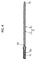
- the other opposite end 71 of the water-distributing member 7 can be covered with a metal net 710 in advice as illustrated in Fig. 4.
- the metal net 710 has fine clearances which are permeable to water, and which can inhibit the roots 91 of the plant 90 from intruding.
- the metal net 710 exhibits a mesh size of 38 or less. If such is the case, even when the roots 91 of the plant 90 grow, the metal net 710 inhibits the roots 91 from intruding into the inside 80, which is covered with the cover member 8, from the opposite end 71 of the water-distributing member 7. Accordingly, the roots 91 hardly entangle with the water-distributing member 7 to cause the problems which result from the disabled water distribution.
- the opposite end 71 of the water-distributing member 7 is disposed in the region where the roots 91 of the plants 90 can be supplied with water, the opposite end 71 can be readily fitted into the cultured-earth region 92 held in the flowerpot 9.
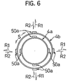
- Figs. 5 and 6 illustrate a modified version of the First Preferred Embodiment in which the outer-periphery holding portion 50 of the holder 5 of the present water-supplying apparatus 1 is modified.
- an outer-periphery holding portion 50a enables the holder 5 to detachably hold a plurality of water-supplying containers 4a and 4b having different sizes.
- the outer-periphery holding portion 50a is formed integrally with the base member 30 of the water reservoir 3.
- the outer-periphery holding portion 50a enables the holder 5 to detachably hold the water-supplying container 4a whose outside diameter "D1" is 95 mm, and the water-supplying container 4b whose outside diameter "D2" is 100 mm.
- the outer-periphery holding portion 50a includes a plurality of plate-shaped members whose inside diameter "d1" is 95 mm. Note that the inside diameter "d1" is a dimension when none of the water-supplying containers 4a and 4b are installed to the holder 5.
- the plate-shaped members are disposed at equal intervals in the circumferential direction "S”.
- the plate-shaped members extend in the longitudinal direction "P" of the water-supplying containers 4a and 4b.
- the size of the water-supplying container 4a is smaller than that of the water-supplying container 4b.
- the outer-periphery holding portion 50a is slightly deformed elastically in the radial direction "R1" outwardly, thereby producing an elastic repulsion force (or an urging force acting in the direction of "R2" inwardly). Accordingly, the holder 5 can fasten and hold the smaller water-supplying container 4a by the elastic repulsion force.
- the water-supplying container 4b is larger than the water-supplying container 4a.
- the outer-periphery holding portion 50a is deformed elastically in the radial direction "R1" outwardly and more greatly than it is deformed in the above-described operation, thereby producing a larger elastic repulsion force. Accordingly, the holder 5 can fasten and hold the larger water-supplying container 4a by the larger elastic repulsion force.
- the Second Preferred Embodiment i.e., the present water-supplying apparatus 1A
- Figs. 7 and 8 will be hereinafter described with reference to Figs. 7 and 8.
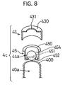
- the present water-supplying apparatus 1A is provided with a ball-shaped check valve 44a and a riser 32, it has the same arrangements as those of the First Preferred Embodiment.
- the ball-shaped check valve 44a is disposed in the opening 40a of the water-supplying container 4c so that it closes the opening 40a by a hydraulic pressure which is exerted when the water-supplying container 4c is transferred in the inverted manner.
- the ball-shaped check valve 44a thus inhibits the water held in the water-supplying container 4c from leaking to the outside via the opening 40a.
- the riser 32 pushes up the ball-shaped check valve 44a to open the opening 40a when the water-supplying container 4c is held invertedly in the water reservoir 3.
- the riser 32 is formed as a rod-shaped member, and is erected from the inner bottom 310 of the water reservoir 3. As later described, a hole 431 is formed in a lid 43.
- the riser 32 has such a thickness that it can provide an interval between itself and the hole 431 to freely supply the water held in the inside 41 of the water-supplying container 4c to the water reservoir 3 when it is fitted into the hole 431.
- the ball-shaped check valve 44a is accommodated movably between the lid 43 and a receptacle 45.
- the lid 43 is detachably installed to the opening 40a of the water-supplying container 4c.
- the receptacle 45 is disposed between the lid 43 and the opening 40a.
- the lid 43 is provided with the hole 431 in the central portion of the top 430.
- the hole 431 is opened and closed by the ball-shaped check valve 44a.
- the receptacle 45 is formed as a concaved and bottomed cylinder-shaped member.
- the receptacle 45 includes a flange 450, and a bottom 452, and a receiving chamber 454.
- the flange 450 is disposed at the top end.
- the bottom 452 is provided with a hole 451 therein.
- the receiving chamber 454 is disposed between the flange 450 and the bottom 452.
- the present water-supplying apparatus 1A operates as follows. After the inside 41 of the water-supplying container 4c is filled with water, the lid 43 is installed to the opening 40a. Note that the receptacle 45 receives the ball-shaped check valve 44a therein, and that it is further disposed between the lid 43 and the opening 40a. At this moment, the flange 450 of the receptacle 45 is placed on the opened-end 400 of the water-supplying container 4c, and is held between the top 430 of the lid 43 and the opened-end 400.
- the water-supplying container 4c is disposed invertedly in the water reservoir 3 as illustrated in Fig. 7.
- the ball-shaped check valve 44a is seated in the hole 431 of the lid 43 by the hydraulic pressure to close the opening 40a.
- the water held in the water-supplying container 4c little leaks while the water-supplying container 4c is replenished with water and is held invertedly in the water reservoir 3 by the holder 5.
- all of the water held in the water-supplying container 4c can be utilized to keep the water held the in the concaved member 31 of the water reservoir 3 at the predetermined water level "H".
- the present water-supplying apparatus 1A operates and produces advantages in the same manner as the First Preferred Embodiment. Moreover, in the present water-supplying apparatus 1A, the ball-shaped check valve 44a is not pushed up by the riser 32 of the water reservoir 3 until the water-supplying apparatus 4c is held invertedly in the water reservoir 3 by the holder 5. Thereafter, the ball-shaped check valve 44a is separated from the hole 431 of the lid 43 against the hydraulic pressure which is exerted by the water held in the water-supplying container 4c. Then, the opening 40a of the water-supplying container 4c is opened forcibly. Finally, the water held in the water-supplying container 4c is supplied to the concaved member 31 of the water reservoir 3. Thus, the water held in the water reservoir 3 can be kept at the predetermined water level "H". As a result, the present water-supplying apparatus 1A can utilize the water held in the water-supplying container 4c without loss.
- the Third Preferred Embodiment i.e., the present water-supplying apparatus 1B
- Figs. 9 and 10 The Third Preferred Embodiment (i.e., the present water-supplying apparatus 1B) will be hereinafter described with reference to Figs. 9 and 10.
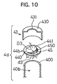
- the present water-supplying apparatus 1B employs a tongue-shaped check valve 44b.
- the tongue-shaped check valve 44d closes the opening 40b of the water-supplying container 4d by a hydraulic pressure, and inhibits the water held in the water-supplying container 4d from leaking to the outside via the opening 40b.
- the present water-supplying apparatus 1B has the same arrangements as those of the Second Preferred Embodiment.
- the lid 43 is detachably installed to the opening 40a of the water-supplying container 4d.
- the tongue-shaped check valve 44b is housed in the lid 43, and is held between the lid 43 and the opening 40b.
- the lid 43 is provided with the hole 431 in the central portion of the top 430.
- the hole 431 is opened and closed by a tongue 44 of the tongue-shaped check valve 44b.
- the tongue-shaped check valve 44b includes a ring-shaped base 45, a connector 440, and the tongue 441.
- the base 45 has an opening 450 having an inside diameter "d3", and is placed on the opened-end 400.
- the connector 440 is connected with the base 45.
- the tongue 441 is formed as a disk virtually, and has an inside diameter "D3" which is smaller than the inside diameter "d3" of the opening 450 formed in the base 45. Accordingly, the tongue 441 can swing up and down in the opening 450 about the connector 440 working as a fulcrum.
- the present water-supplying apparatus 1B operates as follows. After the inside 41 of the water-supplying container 4d is filled with water, the tongue-shaped check valve 44b is held between the top 430 of the lid 43 and the opened-end 400 of the water-supplying container 4d so that the ring-shaped base 45 is placed over the opened-end 400.
- the water-supplying container 4d is disposed invertedly in the water reservoir 3 as illustrated in Fig. 9.
- the tongue-shaped check valve 44b is seated in the hole 431 of the lid 43 by the hydraulic pressure to close the opening 40b.
- the water held in the water-supplying container 4d little leaks while the water-supplying container 4d is replenished with water and is held invertedly in the water reservoir 3 by the holder 5.
- all of the water held in the inside 41 of the water-supplying container 4d can be utilized to keep the water held in the concaved member 31 of the water reservoir 3 at the predetermined water level "H".
- the present water-supplying apparatus 1B operates and produces advantages in the same manner as the First Preferred Embodiment. Moreover, in the present water-supplying apparatus 1B, the tongue 441 of the tongue-shaped check valve 44b is not pushed up by the riser 32 of the water reservoir 3 until the water-supplying apparatus 4d is held invertedly in the water reservoir 3 by the holder 5. Thereafter, the tongue 441 swings about the connector 440 which is connected with the ring-shaped base 45 to work as the fulcrum. Consequently, the tongue 441 is separated from the hole 431 of the lid 43 against the hydraulic pressure which is exerted by the water held in the water-supplying container 4d. Then, the opening 40b of the water-supplying container 4d is opened forcibly.
- the water held in the water-supplying container 4d is supplied to the concaved member 31 of the water reservoir 3.
- the water held in the water reservoir 3 can be kept at the predetermined water level "H".
- the present water-supplying apparatus 1B can utilize the water held in the water-supplying container 4d without loss.
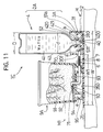
- Fig. 11 generally illustrates the present water-supplying apparatus 1C. Except that the present water-supplying apparatus 1C employs a different water-supplying device 2A, it has the same arrangements as those of the First Preferred Embodiment.
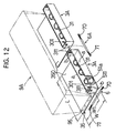
- the water-supplying device 2A includes a water reservoir 3A made from resin, and a table 35. As illustrated in Figs. 12 and 13, the water reservoir 3A is provided with a plurality of opened-end holding portions 51a which detachably hold the reduced-diameter portion 421 of the inverted water-supplying containers 4.
- the table 35 is formed integrally with the water reservoir 3A, and can place the flowerpot 9 (shown in Fig. 1) or a planter 9A (shown in Figs. 11 and 12) thereon.
- the water-reservoir 3A includes the concaved member 31 formed as a rectangle, and three of the opened-end holding portions 51a.
- the concaved member 31 includes the bottom surface 310, two long-side walls “a”, “a”, and two short-side walls “b”, “b”.
- the long-side walls “a”, “a” erect from two sides of the bottom surface 310.
- the short-side walls “b”, “b” erect from another two sides of the bottom surface 310.
- One of the long-side walls “a”, “a” is provided with a hole 301 into which the water distributor 6 is fitted to distribute water to the flowerpot 9 or planter 9A.
- the hole 301 is formed about 35 mm above the predetermined water level "H”.
- the short-side walls "b", “b” are provided with a hole 311 into which an extension water distributor 6A is fitted. Note that the hole 311 is formed about 35 mm above the predetermined water level "H”.
- the opened-end holding portion 51a is formed as a cylinder which erects from the flat inner bottom 310 of the concaved member 31 of the water reservoir 3A. Moreover, the opened-end holding portion 51a has two slits 511 formed in the periphery. The three of the opened-end holding portions 51a are disposed at predetermined intervals in the longitudinal direction of the concaved member 31.
- the table 35 is formed as a plate having a predetermined thickness.
- the table 35 extends horizontally from the bottom end of one of the long-side walls "a", "a" which constitutes the concaved member 31. Accordingly, the width "W” involving the water reservoir 3A, and the width "W1" extending from the long-side wall "a” can be adjusted freely for all purposes.
- the table 35 has an area which can place the legs 95 of the planter 9A thereon.
- a stopper plate 94 is disposed on the inner bottom 93 of the planter 9A so as to inhibit the cultured earth 92 from coming into the space "e" formed in the leg 95.
- the other end 71 of the water-distributing member 7 can be covered with a commercially available root-proof sheet (not shown) in advance.
- the water-supplying devices 2A can hold the three water-supplying containers 4 invertedly at the three opened-end holding portions 51a as illustrated in Fig. 13.
- the water-supplying apparatus 1C can distribute water in a volume required by the plant 90 without shortage or overflow for a much longer period of time.
- the planter 9A having a predetermined weight is placed on the table 35 which is formed integrally with the water reservoir 3A. Consequently, even when the water-supplying containers 4 holding water therein are attached to the opened-end holding portions 51a, which are formed in the water-reservoir 3A of the water-supplying device 2A, the entire water-supplying apparatus 1C is stabilized so that it hardly falls down.
- Figs. 12 and 13 illustrate one of the actual applications of the present water-supplying apparatus 1C.
- two of the above-described water-supplying devices 2A are disposed in series.
- an extension water distributor 6A so that water can be distributed therebetween.
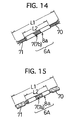
- the extension water distributor 6A employs a tube-shaped cover 8a as illustrated in Fig. 14, it has the same arrangements as those of the water distributor 6 which is used in the First through Third Preferred Embodiments.
- the cover 8a can be fitted around a strip-shaped non-woven cloth whose width is smaller than the inside diameter of the cover 8a. Accordingly, the resulting water distributor 6A has a reduced width at the intermediate portion.
- the water distributor 6, which is used in the First through Third Preferred Embodiments can be employed as it is for the extension water distributor 6A.
- the extension water distributor 6A is immersed in the water, which is held in the water reservoir 3A of one of the neighboring water-supplying devices 2A, at one end 70. Furthermore, the extension water distributor 6A is immersed in the water, which is held in the water reservoir 3A of another one of the neighboring water-supplying devices 2A, at another end 71.
- the two water-supplying devices 2A are disposed in series so that the water can be distributed to the water reservoirs 3c with each other. If such is the case, it is possible to prolong the time period for unattendedly watering the plant 90 without shortage or overflow in an appropriate amount as required by the plant 90 much longer than the case where one and independent water-supplying device 2A is provided.
- the First Modified Version employs a modified version of the opened-end holding portion 51a formed in the water reservoir 3A of the present water-supplying apparatus 1C.
- the slit-shaped openings 511 are made by removing the periphery of the opened-end holding portion 51 all the way up to the top end to communicate with the concaved member 31 of the water reservoir 3A.
- inverted letter U-shaped openings 512 are formed in the opened-end holding portion 51b as shown in Fig. 16.
- the inverted letter-U-shaped openings 512 can be opened so that they are partially immersed in the water held down below in the concaved member 31 at the predetermined water level "H", or they can be opened so that the top end of them is flush with or above the predetermined water level "H".
- the opened-end holding portion 51b of the First Modified Version has the same arrangements as those of the opened-end holding portion 51a of the Fourth Preferred Embodiment.
- the opened-end holding portions 51b of the First Modified Version can hold the water-supplying containers 4, which hold water therein, invertedly.
- the opened-end holding portions 51b can supply the water from the opening 40 of the water-supplying containers 4 to the concaved member 31 of the water reservoir 3A via the inverted letter-U-shaped openings 512.
- the Second Modified Version employs a modified version of the opened-end holding portion 51a formed in the water reservoir 3A in the present water-supplying apparatus 1C.
- hole-shaped openings 513 are formed in the periphery of the opened-end holding portion 51c as shown in Figs. 18 and 19. As illustrated in Fig. 19, the hole-shaped openings 513 can be opened so that they are partially immersed in the water held down below in the concaved member 31 at the predetermined water level "H", or they can be opened so that the top end of them is flush with or above the predetermined water level "H". Except the hole-shaped openings 513, the opened-end holding portion 51c of the Second Modified Version has the same arrangements as those of the opened-end holding portion 51a of the Fourth Preferred Embodiment.
- the opened-end holding portions 51c of the Second Modified Version can hold the water-supplying containers 4, which hold water therein, invertedly.
- the opened-end holding portions 51c can supply the water from the opening 40 of the water-supplying containers 4 to the concaved member 31 of the water reservoir 3A via the hole-shaped openings 513.
- the Third Modified Version employs a modified version of the opened-end holding portion 51a formed in the water reservoir 3A in the present water-supplying apparatus 1C.
- gap-like openings 514 are formed at the bottom of the opened-end holding portion 51d as shown in Figs. 20 and 21.
- the gap-shaped openings 514 can be opened between the predetermined water level "H” and the inner bottom 310 of the concaved member 31, or they can be opened so that the top end of them is flush with or above the predetermined water level "H".
- the opened-end holding portions 51d are formed integrally with the long-side walls "a", "a" of the concaved member 31. Except the gap-like openings 514, the opened-end holding portion 51d of the Third Modified Version has the same arrangements as those of the opened-end holding portion 51a of the Fourth Preferred Embodiment.
- the opened-end holding portions 51d of the Third Modified Version can hold the water-supplying containers 4, which hold water therein, invertedly.
- the opened-end holding portions 51d can supply the water from the opening 40 of the water-supplying containers 4 to the concaved member 31 of the water reservoir 3A via the gap-like openings 514.
- the Fifth Preferred Embodiment i.e., the present water-supplying apparatus 1D
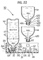
- Fig. 22 The Fifth Preferred Embodiment (i.e., the present water-supplying apparatus 1D) will be hereinafter described with reference to Fig. 22.
- the present water-supplying apparatus 1D is provided with a lid 43, a ball-shaped check valve 44c and a riser 32, it has the same arrangements as those of the Fourth Preferred Embodiment.
- the lid 43 is installed detachably to the reduced cylinder-shaped portion 421 which constitutes the opening 40c of the water-supplying containers 4e.
- the ball-shaped check valve 44c opens and closes the hole 431 which is formed in the central portion of the top 430 of the lid 43.
- the riser 32 is erected from the inner bottom 310 of the concaved portion 31 of the water reservoir 3A so that it pushes up the ball-shaped check valve 44c to open the hole 431 and opening 40c when the water-supplying container 4e is held invertedly by the opened-end holding portion 51.
- the riser 32 When the riser 32 is fitted into the hole 431 which is formed in the central portion of the top 430 of the lid 43, the riser 32 provides an interval between itself and the hole 431. Accordingly, the water held in the inside 41 of the water-supplying container 4e can be supplied freely through the interval. Thus, the riser 32 has such a thickness that it can provide the interval when it is fitted into the hole 431.
- the ball-shaped check valve 44c is accommodated in the inside 41 of the water-supplying container 4c beforehand. Then, the inside 41 of the ordinarily-erected water-supplying container 4e is replenished with water, and the opening 40a thereof is closed by installing the lid 43. The water-supplying container 4e is thereafter inverted. Accordingly, the ball-shaped check valve 44c falls onto the hole 431 of the lid 43 by its own weight, and closes the hole 431 of the lid 43 by its own weight and a hydraulic pressure. While the ball-shaped check valve 44c is closing the hole 431 of the lid 43, the water held in the water-supplying container 4e flows out through the hole 431 in a small amount virtually. However, the water is held in the inside 41 of the water-supplying container 4 in an ample amount. Finally, the water-supplying container 4e is held at the reduced cylinder-shaped portion 421 by the opened-end holding portion 51a in the inverted manner.
- the inverted water-supplying container 4e is thus set to the water reservoir 3 as shown in Fig. 22. Note that, while the inverted water-supplying container 4e is transferred before the setting, the ball-shaped check valve 44c falls onto the hole 431 of the lid 43 by its own weight to close it by its own weight and a hydraulic pressure.
- the ball-shaped check valve 44c is closing the hole 431 of the lid 43 in the setting, the water held in the water-supplying container 4e flows out again through the hole 431 in a small amount virtually. However, the water is still held in the inside 41 of the water-supplying container 4 in an ample amount. Finally, the ball-shaped check valve 44c seats on the hole 431 to close the opening 40a of the water-supplying container 4e.
- the water held in the water-supplying container 4e little leaks through the opening 40a while the water-supplying container 4d is held invertedly by the holder 5 in the water reservoir 3.
- all of the water held in the water-supplying container 4e can be utilized to keep the water held in the concaved member 31 of the water reservoir 3 at the predetermined water level "H".
- the present water-supplying apparatus 1D operates and produces advantages in the same manner as the Fourth Preferred Embodiment. Moreover, in the present water-supplying apparatus 1D, the ball-shaped check valve 44c is not pushed up by the riser 32 of the water reservoir 3 until the water-supplying apparatus 4e is held invertedly by the holder 5 in the water reservoir 3. Consequently, the ball-shaped check valve 44c is separated from the hole 431 of the lid 43 against the hydraulic pressure which is exerted by the water held in the water-supplying container 4e. Then, the opening 40a of the water-supplying container 4e is opened forcibly. Finally, the water held in the water-supplying container 4e is supplied to the concaved member 31 of the water reservoir 3A. Thus, the water held in the water reservoir 3A can be kept at the predetermined water level "H". As a result, the present water-supplying apparatus 1C can utilize the water held in the water-supplying container 4e without loss.
Landscapes
- Engineering & Computer Science (AREA)
- Water Supply & Treatment (AREA)
- Life Sciences & Earth Sciences (AREA)
- Environmental Sciences (AREA)
- Cultivation Receptacles Or Flower-Pots, Or Pots For Seedlings (AREA)
Applications Claiming Priority (4)
| Application Number | Priority Date | Filing Date | Title |
|---|---|---|---|
| JP200213/97 | 1997-07-25 | ||
| JP20021397 | 1997-07-25 | ||
| JP10107552A JPH1189454A (ja) | 1997-07-25 | 1998-04-17 | 規定水位の設定による給水装置 |
| JP107552/98 | 1998-04-17 |
Publications (1)
| Publication Number | Publication Date |
|---|---|
| EP0893054A1 true EP0893054A1 (de) | 1999-01-27 |
Family
ID=26447577
Family Applications (1)
| Application Number | Title | Priority Date | Filing Date |
|---|---|---|---|
| EP98113943A Withdrawn EP0893054A1 (de) | 1997-07-25 | 1998-07-24 | Wassserversorgungsvorrichtung die die Wasserstandshöhe in einem vorgegebenen Bereich haltet |
Country Status (3)
| Country | Link |
|---|---|
| US (1) | US6023886A (de) |
| EP (1) | EP0893054A1 (de) |
| JP (1) | JPH1189454A (de) |
Cited By (3)
| Publication number | Priority date | Publication date | Assignee | Title |
|---|---|---|---|---|
| NL2003277C2 (en) * | 2009-07-24 | 2011-01-25 | Pmm Hoff Holding Bv | A WATER IRRIGATION SYSTEM. |
| WO2012018312A1 (fr) * | 2010-08-05 | 2012-02-09 | Mohamed Tayari | Pots, bacs et jardinieres avec conduits |
| EP1699285A4 (de) * | 2003-12-17 | 2013-08-07 | Anova Solutions Pty Ltd | Wurzel- und wassermanagementsystem für topfpflanzen |
Families Citing this family (11)
| Publication number | Priority date | Publication date | Assignee | Title |
|---|---|---|---|---|
| US6176038B1 (en) | 1997-07-17 | 2001-01-23 | Lynn Morlier | Houseplant maintenance device and method |
| JP4603004B2 (ja) * | 2003-12-04 | 2010-12-22 | 典彦 有田 | 液体供給機構 |
| US7506473B2 (en) * | 2007-02-07 | 2009-03-24 | Al-Qafas Qassim A | Irrigation device |
| JP5216614B2 (ja) * | 2009-01-30 | 2013-06-19 | 山崎教育システム株式会社 | 養液栽培ユニット |
| GB2470204A (en) * | 2009-05-13 | 2010-11-17 | Jim Laflin | Self-acting watering device |
| TW201100003A (en) * | 2009-06-18 | 2011-01-01 | Univ Nat Pingtung Sci & Tech | Active type water-supplying device used for plant pots |
| US20140007501A1 (en) * | 2009-08-13 | 2014-01-09 | Arthur Francis Griebel | Self watering plant system |
| USD632606S1 (en) | 2010-03-25 | 2011-02-15 | Dart Industries Inc. | Planter |
| WO2013169129A1 (pt) * | 2012-04-03 | 2013-11-14 | Quizcamp-Fabrico e Comércio de Produtos Alimentares, S.A. | Sistema integrado modular para germinar sementes, cultivar, plantar, fertilizar e manutenção de planta |
| US20160081279A1 (en) * | 2014-09-19 | 2016-03-24 | Wen-Chi Lai | Automatic Liquid Supply Planting Device |
| US12564147B2 (en) * | 2019-01-25 | 2026-03-03 | Kionna Harris Wells | Closed loop self-watering sub-irrigation planter |
Citations (7)
| Publication number | Priority date | Publication date | Assignee | Title |
|---|---|---|---|---|
| DE837332C (de) * | 1950-09-15 | 1952-04-21 | Hans Seeger | Vorrichtung zur selbsttqaetigen Bewaesserung von in Toepfen, Kaesten oder Schalen eingesetzten Pflanzen |
| FR1517928A (fr) * | 1967-02-07 | 1968-03-22 | Dispositif d'arrosage à réservoir indépendant applicable aux récipients de culture | |
| JPS5134834U (de) | 1974-09-04 | 1976-03-15 | ||
| FR2469870A1 (fr) * | 1979-11-26 | 1981-05-29 | Peeters Jacques | Dispositif distributeur d'eau pour plantes d'appartement en pot pendant les absences prolongees base sur le principe des niveaux de liquide constant |
| DE9319107U1 (de) * | 1993-12-13 | 1994-03-03 | Strohmaier, Robert, 81247 München | Selbsttätig dosierende Vorrichtung zur Langzeitbewässerung oder -befeuchtung und gegebenenfalls Nährstoffzuführung von Topfpflanzen und anderen feuchtzuhaltenden Kulturen |
| JPH0646450U (ja) | 1992-12-03 | 1994-06-28 | 隆 山川 | 植物栽培用給水器具及び給水具 |
| GB2308797A (en) * | 1995-12-29 | 1997-07-09 | Richard William Maris | Plant watering device |
Family Cites Families (6)
| Publication number | Priority date | Publication date | Assignee | Title |
|---|---|---|---|---|
| FR1447333A (fr) * | 1965-06-15 | 1966-07-29 | Châssis perfectionné | |
| US3786598A (en) * | 1971-08-10 | 1974-01-22 | R Stadelhofer | Self-feeding watering system for potted nursery plants |
| JPS5134834A (ja) * | 1974-09-20 | 1976-03-24 | Toyo Satsushi Kogyo Kk | Aruminiumuzairyonitosoohodokosu hoho |
| FR2446592A1 (fr) * | 1979-01-16 | 1980-08-14 | Douhet De Villossanges Hugues | Dispositif pour culture, notamment d'interieur |
| GB2139465B (en) * | 1983-05-13 | 1986-10-29 | John Upton | Plant pots |
| JPH0646450A (ja) * | 1992-07-21 | 1994-02-18 | Sony Corp | 画像信号のプリント装置 |
-
1998
- 1998-04-17 JP JP10107552A patent/JPH1189454A/ja active Pending
- 1998-07-24 EP EP98113943A patent/EP0893054A1/de not_active Withdrawn
- 1998-07-27 US US09/122,717 patent/US6023886A/en not_active Expired - Fee Related
Patent Citations (7)
| Publication number | Priority date | Publication date | Assignee | Title |
|---|---|---|---|---|
| DE837332C (de) * | 1950-09-15 | 1952-04-21 | Hans Seeger | Vorrichtung zur selbsttqaetigen Bewaesserung von in Toepfen, Kaesten oder Schalen eingesetzten Pflanzen |
| FR1517928A (fr) * | 1967-02-07 | 1968-03-22 | Dispositif d'arrosage à réservoir indépendant applicable aux récipients de culture | |
| JPS5134834U (de) | 1974-09-04 | 1976-03-15 | ||
| FR2469870A1 (fr) * | 1979-11-26 | 1981-05-29 | Peeters Jacques | Dispositif distributeur d'eau pour plantes d'appartement en pot pendant les absences prolongees base sur le principe des niveaux de liquide constant |
| JPH0646450U (ja) | 1992-12-03 | 1994-06-28 | 隆 山川 | 植物栽培用給水器具及び給水具 |
| DE9319107U1 (de) * | 1993-12-13 | 1994-03-03 | Strohmaier, Robert, 81247 München | Selbsttätig dosierende Vorrichtung zur Langzeitbewässerung oder -befeuchtung und gegebenenfalls Nährstoffzuführung von Topfpflanzen und anderen feuchtzuhaltenden Kulturen |
| GB2308797A (en) * | 1995-12-29 | 1997-07-09 | Richard William Maris | Plant watering device |
Cited By (4)
| Publication number | Priority date | Publication date | Assignee | Title |
|---|---|---|---|---|
| EP1699285A4 (de) * | 2003-12-17 | 2013-08-07 | Anova Solutions Pty Ltd | Wurzel- und wassermanagementsystem für topfpflanzen |
| NL2003277C2 (en) * | 2009-07-24 | 2011-01-25 | Pmm Hoff Holding Bv | A WATER IRRIGATION SYSTEM. |
| WO2011010930A1 (en) * | 2009-07-24 | 2011-01-27 | P.M.M. Hoff Holding B.V. | A water irrigation system |
| WO2012018312A1 (fr) * | 2010-08-05 | 2012-02-09 | Mohamed Tayari | Pots, bacs et jardinieres avec conduits |
Also Published As
| Publication number | Publication date |
|---|---|
| JPH1189454A (ja) | 1999-04-06 |
| US6023886A (en) | 2000-02-15 |
Similar Documents
| Publication | Publication Date | Title |
|---|---|---|
| US6023886A (en) | Water-supplying apparatus capable of keeping predetermined water level | |
| US6648239B1 (en) | Device for dispensing animal scents | |
| CA2436915C (en) | Moulded body for improving cultivating conditions of plants | |
| US5212904A (en) | Fertilizing apparatus | |
| JP4603004B2 (ja) | 液体供給機構 | |
| US6205706B1 (en) | Self-watering planting reservoir | |
| US5329729A (en) | Plant irrigation system | |
| US5189834A (en) | Apparatus for irrigating container grown plants in a closed system | |
| CA2359618C (en) | A dispenser for releasing a substance into a toilet bowl | |
| GB2250171A (en) | Plant pot | |
| US5247762A (en) | Hydraulic planter system | |
| WO2001067846A1 (en) | Plant watering device | |
| KR101327568B1 (ko) | 화분용 급수장치 | |
| US5581937A (en) | Plant watering apparatus | |
| KR101581332B1 (ko) | 화분용 급수장치 | |
| GB2030037A (en) | Self-watering plant pots | |
| JP2587220Y2 (ja) | 植木用の水等供給装置 | |
| JPH11192031A (ja) | 自動給水植木鉢 | |
| JP2001078595A (ja) | 植木鉢の自動給水装置及びその部品 | |
| KR200195166Y1 (ko) | 자동 급수용 화분 받침대 | |
| JP3967763B2 (ja) | 液体供給機構 | |
| JPH065437U (ja) | プランター | |
| WO1995010934A1 (en) | Self-regulating system for watering plants | |
| WO2001035724A1 (en) | An autonomous planter and method | |
| JP2005185280A (ja) | 液体供給機構 |
Legal Events
| Date | Code | Title | Description |
|---|---|---|---|
| PUAI | Public reference made under article 153(3) epc to a published international application that has entered the european phase |
Free format text: ORIGINAL CODE: 0009012 |
|
| 17P | Request for examination filed |
Effective date: 19980724 |
|
| AK | Designated contracting states |
Kind code of ref document: A1 Designated state(s): DE FR GB IT |
|
| AX | Request for extension of the european patent |
Free format text: AL;LT;LV;MK;RO;SI |
|
| AKX | Designation fees paid |
Free format text: DE FR GB IT |
|
| 17Q | First examination report despatched |
Effective date: 20020411 |
|
| STAA | Information on the status of an ep patent application or granted ep patent |
Free format text: STATUS: THE APPLICATION IS DEEMED TO BE WITHDRAWN |
|
| 18D | Application deemed to be withdrawn |
Effective date: 20021022 |