EP0892894B1 - Verfahren zum betreiben einer hydrodynamischen kupplung und hydrodynamische kupplung - Google Patents
Verfahren zum betreiben einer hydrodynamischen kupplung und hydrodynamische kupplung Download PDFInfo
- Publication number
- EP0892894B1 EP0892894B1 EP98904110A EP98904110A EP0892894B1 EP 0892894 B1 EP0892894 B1 EP 0892894B1 EP 98904110 A EP98904110 A EP 98904110A EP 98904110 A EP98904110 A EP 98904110A EP 0892894 B1 EP0892894 B1 EP 0892894B1
- Authority
- EP
- European Patent Office
- Prior art keywords
- filling
- hydrodynamic clutch
- pressure
- filling level
- dynamic pressure
- Prior art date
- Legal status (The legal status is an assumption and is not a legal conclusion. Google has not performed a legal analysis and makes no representation as to the accuracy of the status listed.)
- Expired - Lifetime
Links
- 238000000034 method Methods 0.000 title claims description 25
- 230000008569 process Effects 0.000 title claims description 17
- 238000001514 detection method Methods 0.000 claims description 63
- 238000001816 cooling Methods 0.000 claims description 23
- 239000002826 coolant Substances 0.000 claims description 13
- 238000005429 filling process Methods 0.000 claims description 9
- 230000007704 transition Effects 0.000 claims description 3
- 230000014759 maintenance of location Effects 0.000 claims 16
- 230000005484 gravity Effects 0.000 claims 2
- 230000008878 coupling Effects 0.000 description 98
- 238000010168 coupling process Methods 0.000 description 98
- 238000005859 coupling reaction Methods 0.000 description 98
- 238000010586 diagram Methods 0.000 description 20
- 238000013461 design Methods 0.000 description 17
- 239000012530 fluid Substances 0.000 description 14
- 238000006243 chemical reaction Methods 0.000 description 11
- 230000001276 controlling effect Effects 0.000 description 9
- 230000008859 change Effects 0.000 description 5
- 230000004044 response Effects 0.000 description 4
- 230000008901 benefit Effects 0.000 description 3
- 239000007788 liquid Substances 0.000 description 3
- 238000012544 monitoring process Methods 0.000 description 3
- 230000001105 regulatory effect Effects 0.000 description 3
- XLYOFNOQVPJJNP-UHFFFAOYSA-N water Substances O XLYOFNOQVPJJNP-UHFFFAOYSA-N 0.000 description 3
- 230000005540 biological transmission Effects 0.000 description 2
- 230000003111 delayed effect Effects 0.000 description 2
- 230000001419 dependent effect Effects 0.000 description 2
- 230000000694 effects Effects 0.000 description 2
- 238000005516 engineering process Methods 0.000 description 2
- 238000007654 immersion Methods 0.000 description 2
- 238000009434 installation Methods 0.000 description 2
- 239000000463 material Substances 0.000 description 2
- 241001295925 Gegenes Species 0.000 description 1
- 230000004913 activation Effects 0.000 description 1
- 230000002411 adverse Effects 0.000 description 1
- 238000013459 approach Methods 0.000 description 1
- 230000033228 biological regulation Effects 0.000 description 1
- 230000015572 biosynthetic process Effects 0.000 description 1
- 230000006866 deterioration Effects 0.000 description 1
- 238000011161 development Methods 0.000 description 1
- 210000003027 ear inner Anatomy 0.000 description 1
- 238000009415 formwork Methods 0.000 description 1
- 230000017525 heat dissipation Effects 0.000 description 1
- 230000002706 hydrostatic effect Effects 0.000 description 1
- 238000012806 monitoring device Methods 0.000 description 1
- 238000004091 panning Methods 0.000 description 1
- 238000012546 transfer Methods 0.000 description 1
- 238000011144 upstream manufacturing Methods 0.000 description 1
Images









Classifications
-
- F—MECHANICAL ENGINEERING; LIGHTING; HEATING; WEAPONS; BLASTING
- F16—ENGINEERING ELEMENTS AND UNITS; GENERAL MEASURES FOR PRODUCING AND MAINTAINING EFFECTIVE FUNCTIONING OF MACHINES OR INSTALLATIONS; THERMAL INSULATION IN GENERAL
- F16D—COUPLINGS FOR TRANSMITTING ROTATION; CLUTCHES; BRAKES
- F16D33/00—Rotary fluid couplings or clutches of the hydrokinetic type
- F16D33/06—Rotary fluid couplings or clutches of the hydrokinetic type controlled by changing the amount of liquid in the working circuit
- F16D33/16—Rotary fluid couplings or clutches of the hydrokinetic type controlled by changing the amount of liquid in the working circuit by means arranged externally of the coupling or clutch
Definitions
- the invention relates to a method for operating a hydrodynamic Coupling, in detail with the features from the upper range of the Claim 1; also a hydrodynamic coupling, in detail with the Features from the preamble of claim 8.
- volumetric Cooling i.e. the replacement of the equipment in the working cycle simultaneous removal of a certain amount of heated equipment and feeding of lower temperature equipment in the corresponding amount.
- FR-A-1 236 353 discloses a hydrodynamic clutch for which the state of full filling and its detection is desired.
- the clutch has two paddle wheels, a pump wheel and a Turbine wheel, the turbine wheel being rotatably connected to the Pump wheel coupled shell in the axial and radial directions below Formation of a space is enclosed.
- a storage space is coupled in a rotationally fixed manner, in which the intermediate space leaked equipment from the work area Through openings emerges.
- the through openings are such ordered that an exit is achieved only when full becomes.
- the passage openings are therefore only at actual Full filling active, there is no transition beforehand. The resource occurs thus not during the filling process in a particular one Relationship to the degree of filling from the work space through the shell into the Storage space.
- a major problem with hydrodynamic couplings is that depending on the application during commissioning or activation due to the Rotation of the rotor parts of the clutch in a housing there is a risk not to fill the clutch exactly, but to overfill it, as a certain one Degree of filling is very difficult to maintain exactly. In this case are then due to additional splashing losses between the runner parts themselves, i.e. the individual paddle wheels, and the housing and the rotor parts a deterioration in efficiency and an increasing Leakage at the individual labyrinths, i.e. the Equipment management lines.
- a solution which for To avoid these disadvantages, an additional drain line from the housing to the tank is not desirable.
- the supply line or the actuator for controlling the Inlet controlled by a fill signal acts as a fill signal for example the pressure in the drain line.
- This will have a Device for recording the current pressure value in the drain line measured in the work area.
- Via a pressure switch Exceeding a certain pressure the system is electrically locked, so that a supply of additional equipment is prevented.
- This signal on the one hand is very imprecise due to the different boundary conditions and the further often not sufficient to overfill the clutch prevent.
- the pressure switch itself itself must always do this during commissioning can be set very precisely and is also able to withstand the pressure peaks Open fill valve exposed in the feed line.
- the invention is therefore based on the object of a method for operating to develop a hydrodynamic clutch so that the Disadvantages of the prior art can be avoided.
- the Solution according to the invention should be characterized by a low constructive and Distinguish tax and regulatory expenditure.
- the constructive Execution to realize the overfill protection should also be very be insensitive to interference and a maximum permissible degree of filling, which the generally maximum or a freely definable filling level can correspond as accurately and very quickly as possible and on it can react.
- the solution according to the invention is characterized by the features of claim 1 characterized.
- the design is characterized by the features of Claim 8 characterized.
- Advantageous configurations are in each of the Subclaims described.
- a hydrodynamic clutch is included at least two paddle wheels, a primary paddle wheel and one Secondary impeller, which together form at least one toroidal Form work space, operated such that only two Fill level states - a first fill level state that represents the state the non-filling and the partial filling, and a second Fill level condition that describes the maximum allowable fill level, can be distinguished, the first degree of filling being a certain one first, very low first pressure value is assigned and the second Degree of filling a second, increased compared to the first pressure value Print.
- the work space is coupled with a storage space. In one certain ratio to the filling level of the clutch Consumables from the work room into the storage space.
- the Operating fluid level tapped via a dynamic pressure detection device.
- the dynamic pressure detection device works so to speak on the black and white principle.
- the degree of filling becomes essentially nonexistent, or only a very small one constant pressure detected and in a second filling level state pressure significantly increased compared to the first degree of filling.
- the device becomes at least indirect influence on the feed quantity, generally an actuator controlled a valve device assigned to the inlet line and the Resource supply reduced or interrupted.
- the pressure signal is via the Dynamic pressure generation or detection device from which is in the storage space adjusting dynamic pressure.
- the maximum permissible degree of filling is the actual, correspond to the maximum permissible degree of filling. This is generally 100%. However, it is also conceivable for the maximum permissible degree of filling to be defined in such a way that it is specific to a specific one The intended use corresponds to the degree of filling that can be predetermined. This degree of filling can be maintained by any partial filling in relation to the maximum permissible degree of filling.
- a catch channel is assigned to the actual work space, which forms a storage space which is coupled to the work space at least indirectly for the purpose of supplying operating resources.
- the gutter is arranged on a diameter which, during operation of the hydrodynamic coupling, enables at least one filling of the storage space which is proportional to the degree of filling of the hydrodynamic coupling.
- a dynamic pressure detection device communicating with the work space, formed by the gutter, a dynamic pressure detection device, preferably in the form of a dynamic pressure tube for the purpose of scanning the level in the storage space is introduced.
- the dynamic pressure generation or detection device is arranged opposite the storage space in such a way that it or, in the case of a dynamic pressure tube, its opening lies above or outside the operating fluid level in the storage space when the coupling is not or only partially filled, so that it is not filled in this filling level state. In this case, no operating material is discharged via the dynamic pressure pipe and therefore no pressure signal is generated.
- the dynamic pressure tube is arranged in the storage space in such a way that it only detects a high dynamic dynamic pressure when there is an operating medium level in the storage space which corresponds to the maximum degree of filling of the coupling.
- the opening of the dynamic pressure tube projects into a space in the storage space that is free of operating resources. In this state, no pressure or only a very low pressure is detected via the dynamic pressure generation or detection device or a corresponding pressure signal is generated. This low pressure corresponds, for example, to the pressure which arises in an unfilled and open tube in the atmosphere.
- the maximum degree of filling can actually be a maximum Filling degree, generally 100%, correspond. However, it is also conceivable, the maximum filling level as one for a concrete Use case to define the degree of filling to be observed.
- the maximum Degree of filling which corresponds to the degree of filling that can be defined then by each degree of filling less than the actually maximum permissible Degree of filling definable.
- the definition of the degree of filling to be maintained can be set by setting the Position of the dynamic pressure generation or detection device, in particular the opening for receiving the equipment in the storage space. This can be done by moving in a vertical direction, i.e. in installation position Moving in the radial and circumferential direction in the storage space or Panning can be changed. The entire range can be used as a setting range Circumferential area can be viewed. The change in position can can be permanently set for a specific application or additionally during adaptable to the operation. This has the advantage that with a Overfill protection different applications of a hydrodynamic Coupling of certain design and size through active adaptability itself changing requirements can be covered.
- An advantageous embodiment is to approach a separate gutter waive and to use the equipment gutter. This has the advantage that existing components can be used.
- the Pitot tube in a separate filling segment which is the Resource gutter is arranged upstream, the knowledge is used that a Draining from the equipment trough only takes place until the maximum Filling, i.e. the state of full filling has not yet been reached.
- the gutter can be used as a separate component with the appropriate rotor parts Assignment to the work space can be releasably connected.
- the gutter with a paddle wheel as a structural Unity, i.e. made in one piece.
- the dynamic pressure generation or detection device which preferably is designed as a dynamic pressure pipe, has a bearing an opening area Part on. This part is preferably substantially parallel to that arranged in the storage space adjusting equipment level. A Arrangement inclined or perpendicular to it is also conceivable.
- the Opening area extends at least partially perpendicular to the radial Direction and in the circumferential direction, taking into account the direction of rotation is. The opening area preferably faces completely in the circumferential direction and is arranged substantially perpendicular to this.
- the solution according to the invention is of any kind of hydrodynamic Couplings with variable filling can be used.
- the couplings can be used as Single-circuit clutches, which have a primary and a secondary impeller have, which together form a toroidal working space, or also as multi-circuit clutches, in which a plurality of primary and Secondary vane wheels form a large number of work spaces his.
- the gutter can be the primary as well be assigned to the secondary paddle wheel or a shell. in the latter case is only an assignment to one of the paddle wheels, generally due to the external impellers constructive conditions possible.
- the coupling between storage space and work space can be carried out in many ways his.
- the through opening allows one Transfer of equipment from the work area to the storage space.
- the through opening can be designed differently. Through openings in the form of through holes or elongated holes, which each on a certain diameter of the paddle wheel are arranged are conceivable.
- the through openings can be between the individual blades in the Blade base or in a radially inside the blade wheel lying area, which is free from the blading.
- the filling can also be dependent from the speed difference, i.e. the slip between the primary and the Secondary wheel, so that a short bridging of the time Pressure signals may be required.
- the part of the dynamic pressure tube carrying the opening is preferably in the arranged essentially parallel to the equipment level in the storage space.
- the Opening itself can be perpendicular or inclined to the equipment level be executed. independence from the direction of rotation is ensured by the Providing at least two, with respect to the orientation of the one opening supporting part of a pitot tube directed in opposite directions Pitot tubes, for example through a check valve can be coupled together.
- Another embodiment provides two pitot tubes, each with a separate pressure switch are coupled together.
- the pitot tubes dip through the the gutter and the outer dimensions of the paddle wheel, which the gutter is assigned, certain storage space that it is at a maximum filling level a dynamic pressure by immersing the Pitot tube captured in the equipment in the gutter.
- the maximum degree of filling does not necessarily have to correspond to the full filling. On any degree of filling, which is defined as the maximum degree of filling also conceivable. This maximum degree of filling can accordingly
- the application of the hydrodynamic coupling can be defined.
- the Pitot tube can be made adjustable for this purpose, so that the Immersion height in the equipment in the gutter is variable. This offers the advantage of realizing a simple customization option Overfill protection to meet different requirements.
- An embodiment of the component supporting the opening is in the radial direction also conceivable.
- the gutter can, as already stated, as a separate gutter on Clutch rotor be executed, but there is also the Possibility to move the equipment entry channel, i.e. the for the purpose of inflow to use the gutter coupled to the work area with the inlet pipe. in the the latter case are no further constructive measures the paddle wheels of the hydrodynamic clutch, but there is the possibility of existing facilities recourse.
- the pressure signal generated by the dynamic pressure tube which for Control of the actuator of a device to influence the Filling levels, in particular a device for controlling the Supply volume used for the work area can be in a higher-level Control or regulating device are processed.
- Another possibility consists in the direct control of the actuator via the device for Detection of the degree of filling of the clutch at least indirectly characteristic size.
- the actuating device is effective in that that the filling is either interrupted or reduced. Since in As a rule, the pressure signal does not take effect directly on the actuating device is, is between the device for detecting the degree of filling Conversion device for converting the pressure signal into a electrical control signal required.
- a pressure switch is preferably used for this purpose intended.
- the solution according to the invention for realizing overfill protection by Detection of the degree of filling is of any kind of hydrodynamic couplings applicable. This is preferably done Use with hydrodynamic couplings, their work spaces too can be emptied during operation of the coupling.
- a control device is provided. This includes at least one control device, each of which has at least one first Has input and a first output.
- the first entrance to the Control device is with the dynamic pressure generation or Detection device can be coupled at least indirectly.
- the first exit of the Control device is at least indirectly with the device for Influencing the supply of equipment to the work area of the hydrodynamic coupling can be coupled.
- the control device for example, either determined dynamic pressure value or one proportional to this Size assigned a manipulated variable Y, which on the device for Influencing the supply of resources to the work area at least indirectly takes effect.
- a manipulated variable Y which on the device for Influencing the supply of resources to the work area at least indirectly takes effect.
- In the simplest case only that is preferred Input signal at the control device, which increased the second Corresponds to the pressure value, assigned a manipulated variable.
- the control device acts as a simple conversion device, i.e. this arranges one Input signal either a control variable or not.
- the manipulated variable Y which is output at the output of the control device can either directly on an actuator of the device Influencing the amount of equipment supplied to the work area of the hydrodynamic coupling or indirectly, i.e. indirectly on this Actuator become effective.
- the manipulated variable Y it can be an electrical, a hydraulic or a pneumatic or act a mechanical quantity.
- control device can either through the appropriate selection of components and their coupling or can be realized via a corresponding microprocessor control.
- the fill level condition detection and the control of the device for influencing the Resource supply quantity to the working space of the hydrodynamic coupling can, for example, at least two pressure switch devices be provided.
- One pressure switch device is one Direction of rotation of the clutch and thus an opening area on the Back pressure generation or detection device assigned.
- the Pressure switches take on the task of actuating the Device for influencing the amount of resource supply to To control the working area of the hydrodynamic clutch electrically.
- the pressure switching device comprises a switch, which corresponding coupling realized. In the first switch position of the switch the pressure switch, usually when a fill signal is present the actuating device of the device for influencing the Operating fluid supply to the work area is controlled in such a way that Equipment can get to the work area.
- the release of the The supply line to the work area can also be stepless.
- the switch is moved to a second switching position.
- this second Switching position is the device for influencing the Resource supply quantity to the working space of the hydrodynamic coupling brought into a switching position in which the equipment supply to Work space is reduced or interrupted.
- the switches of the pressure switching device are directly over the with the Back pressure generation or detection device generated back pressure driven. This means that either the dynamic pressure at the switch becomes effective and actuates it, or one for dynamic pressure proportional size. However, the former option is preferred realized.
- the control device contains at least one each Delay device in the form of a delay relay, which the individual pressure switching devices is connected downstream.
- the Device for influencing the amount of operating supplies to Working area of the hydrodynamic clutch, i.e. the filling valve, at Occurrence of a corresponding, the maximum degree of filling corresponding signals, delayed with a certain period of time is switched to overcrowding during a short-term operational To prevent pressure drop at the pressure switch.
- the period is chosen as low as possible. Periods of> 0 to are preferred 5 seconds realized. This period can either be according to the Use case can be set or already by designing the Delay devices are fixed.
- for additional switching and safety functions including the normally open functions be used by pressure switches.
- a version with a delay device is used with clutches regulated coolant circulation preferably not realized because the regulation could be adversely affected.
- the hydrodynamic clutch may be used to start a machine For example, only fill until one of the two Pressure switch devices a signal is present. Should the workspace however still not be completely filled, that means the signal from the Back pressure generation or detection device falls after a certain Period, a refill will be carried out automatically.
- the so-called filling valve As long as of the starting process is opened until the pressure switch device responds. Then the nominal operating point is waited for and possibly one Refill if the signal drops from the dynamic pressure generation or Detection device made to the first pressure value. additionally the drain valve, i.e. the device for influencing the Drainage rate from the work area, clocked open until the Pressure switching device the device for influencing the feed quantity no longer controlled.
- the filling valve is operated in cycles until the Level detection responds again, i.e. the dynamic pressure generation or detecting device generates the second pressure value.
- the degree of filling defined and to be determined depends, however the position of the dynamic pressure generation or detection device, especially the opening area in the storage space.
- the position of the Back pressure generation or detection device in the storage space or their The opening area opposite the storage space defines one defined maximum permissible filling level. This corresponds to general the maximum permissible degree of filling of 100%, however but also describe a certain degree of partial filling. It is also conceivable an adjustability of the maximum permissible degree of filling by the Back pressure generation or detection device adjustable in the storage space is arranged.
- Coupling versions in which the work area Coolant circuit during continuous operation for the purpose of cooling assigned, i.e. part of the equipment is used during operation emitted from the work space and this again via a circuit fed, and this circuit separately a feed and a Drain line can be activated for the purpose of volumetric cooling, for example, via appropriate valve devices, is after Response of the temperature monitoring for the exchange of equipment first the drain valve in the outlet from the work space hydrodynamic clutch opened and after an adjustable period of time, which can also be zero, also switched on the filling valve. In this In this case, resources are taken from the working cycle and at the same time or new, cooled equipment is supplied with a short time offset. Speaks the signal for the during this resource exchange Fill level condition detection, i.e.
- the Device for influencing the supply quantity to the work area i.e. the Filling valve closed for the set time to prevent overfilling prevent. If the temperature has dropped below a permissible limit, the clutch is filled again as defined when starting, i.e. the establishment to influence the amount of equipment supplied to the work area switched that the resource supply coupled to the work space is, after the occurrence of a signal for the second pressure value at the Condition detection device the filling valve is closed again.
- the Start-up time, the power consumption as a function of the time Operating medium temperature lead to fault or warning messages that as further input variables for controlling the actuation devices of the individual valves must also be taken into account. Furthermore, also the clutch fill time lead to a message when a certain predefined value is exceeded.
- valve devices for influencing the cross section to be released mechanically, in the inlet or outlet line of the work area operated by electric motor, electromagnetic, hydrostatic or pneumatic become.
- To control the actuators is between Back pressure generating or measuring device and actuating device to provide at least one signal conversion device.
- FIGS. 2a and 2b are the functional diagram of a Generic hydrodynamic coupling, here using the example of a Coupling with two working circuits and associated closed Resource cooling circuit, as well as a characteristic curve to represent the Dependence of the instantaneous pressure p in the drain lines on Fill level of the coupling shown.
- FIG. 2a illustrates a functional diagram in a simplified representation a generic known from the prior art hydrodynamic clutch 1, which as a double circuit clutch closed equipment circulation in a closed cooling circuit is executed.
- this coupling 1 comprises two Bucket wheels, a primary bucket wheel 2 and its secondary bucket wheel 3, which together have at least two toroidal working spaces 4 and 5 form.
- the primary impeller 2 is at least via a drive shaft 6 indirectly with a drive machine not shown in detail here coupled.
- the secondary impeller is with an output shaft 7 for Coupling can be connected to the driven side in a rotationally fixed manner.
- the two toroidal work spaces 4 and 5 are equipped with an operating medium fillable. Oil or water can be used as equipment.
- the equipment is used in the operation of the hydrodynamic coupling Torque transmission device in the toroidal workrooms 4 and 5 circulates and thus forms between the two paddle wheels, the Primary impeller 2 and the secondary impeller 3 each have one closed working cycle 9.1 and 9.2.
- a coolant circuit 10 is assigned to the working circuit in order to dissipate the heat accumulating in the working circuits 9.1 and 9.2.
- the operating medium is dispensed through openings (not shown here) in the area of the outer diameter D AS of the primary impeller wheels during the operation of the hydrodynamic clutch 1 into a pump shell 11 which is coupled to the primary impeller wheel 2 in a rotationally fixed manner.
- the pump shell 11 is arranged in the radial direction with respect to the coupling axis A in the area of the outer circumference U AS of the two paddle wheels 2 and 3.
- the operating medium is received by at least one dynamic pressure pipe 12 which is counter to the direction of rotation.
- This dynamic pressure tube 12 is part of the coolant circuit 10 and opens into a line 13, which functions as an outlet line from the pump bowl 11 and at the same time as an inlet line to a cooling device 14, which can be designed as a cooler or as a heat exchanger.
- the cooling device 14 is connected via a line 15 to an operating means feed channel 16 to the work rooms 4 and 5.
- the coolant circuit 10 is a closed circuit. The line course of this circuit 10 can also be used for filling and emptying the toroidal work spaces 4 and 5.
- the work rooms 4 and 5 are assigned at least indirectly via the coolant circuit 10 a supply line 17 and a discharge line 18, which are coupled to an operating fluid tank 19.
- These individual lines, here the supply line 17 and the discharge line 18, can be connected via corresponding devices in the form of valve devices.
- the drain line 18 is connected by means of a switching valve which functions as an emptying valve, for example in the form of a 2/2-way valve 20.
- the supply line 17 is connected by means of a switching valve which functions as a filling valve in the form of a 3/2-way valve 21.
- the filling quantity is influenced via the 3/2-way valve 21, which in a first switching position I 21 decouples the supply line 15 to the equipment inlet channel 16 from the supply line 17 and in a second switching position II 21 connects the supply line 17 to the supply line 15 ,
- the drain line in particular the line 13 in the coolant circuit 10, in which is part of the equipment during heat dissipation from the working cycle 9.1 or 9.2 via a cooler back into the Working cycle is performed, a device for detecting the pressure p assigned.
- This device is designated 23 here.
- FIG. 2b shows a diagram in which the pressure p in Dependence on the coupling filling or the filling level in% is plotted. From this it can be seen that only from one Coupling filling, which corresponds to the maximum filling level, which in the Rule is 100%, a change in the pressure values in the lines it can be noted that the pressure value curve has increased Shows increase. In the range of a clutch fill level from 0% to 100 %, the pressure p generated in the line system increases substantially continuously.
- the hydrodynamic coupling 1 comprises a cooling circuit 10 assigned to the working circuit, and inlet or outlet lines 17 or 18 assigned to the working spaces 4 or 5.
- a so-called gutter 26 is assigned to the working space or working spaces 4 or 5, which preferably runs in the circumferential direction of the hydrodynamic coupling 1 and is arranged in the radial direction in relation to the coupling axis A in a region which, based on the dimensions in the radial direction, extends at most over the maximum diameter of the working space 4 or 5.
- This gutter 26 is connected to the work space 4 and 5 in a communicating manner.
- the connection takes place, for example, in the form of a through opening 27, which can be designed in various ways and in the radial direction in a region between an outer diameter of the channel d ra , which corresponds to the radially outer boundary of the collecting channel 26, and that, the collecting channel in the radial direction the smallest diameter-limiting areas, for example the surfaces 29 and 30 is incorporated into the primary impeller 2.
- the through openings 27 can be arranged either in the blade-free, radially inner region of the primary blade wheel 2 or, preferably, in the blade base of the bladed part 31 of the primary blade wheel 2.
- the arrangement of the gutter 26 and the through opening 27 with respect to the paddle wheel is dependent on the desired filling depending on the degree of filling of the clutch 1.
- the through openings 27 can be designed as through bores, which are circular in shape or in the form of elongated holes, which are preferably extend over at least part of the circumference of the impeller on a certain diameter.
- the filling level in the storage space 40 described by the gutter 26, which is determined by the degree of filling in the hydrodynamic coupling 1, in particular the working spaces 4 and 5 and the design of the through openings 27, is tapped by means of a dynamic pressure pipe 32.
- the dynamic pressure pipe 32 is designed and arranged in such a way that filling with liquid takes place only from a fill level 34 in the gutter 26, which corresponds to a maximum permissible degree of filling in the work spaces 4 and 5.
- a so-called dynamic pressure p is dynamically recorded, which corresponds to a second pressure value p 2 , which is higher than a first pressure value p 1 without filling the dynamic pressure tube 32 with operating medium, as a manipulated variable for the application of the 3/2-way valve 21 Influencing the amount of equipment supplied to the working cycle 9.1 or 9.2 is used.
- the maximum permissible degree of filling preferably corresponds to a maximum degree of filling of 100%.
- the maximum permissible filling quantity can be determined by the upper one Filling limit, a filling level of 100% can be determined, or else be freely selectable between a filling level of 0% and 100%.
- the opening of the dynamic pressure pipe is always according to the degree of filling 32 can be filled with operating funds and an operating equipment level 34 Arrange reaching storage space 40.
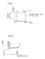
- FIG. 1b the dependence of the determined dynamic pressure values on the clutch filling is plotted in a diagram for the embodiment according to the invention. From this it can be seen that with partial filling, ie an operating state of the hydrodynamic coupling 1, in which the fluid level 34 in the storage space 40 of the gutter 26 is below the dynamic pressure tube 32, a pressure value p is determined in the dynamic pressure tube 32, which essentially corresponds to the air pressure.
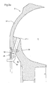
- Figures 3a and 3b illustrate in a section of a Paddle wheel, preferably the primary paddle wheel 2, each one more Possibility of designing the connection between the work space, here the work space 4, and the gutter 26 and that through the gutter 26 and the outer contour 37 of the primary impeller defines storage space 40.
- FIG. 3a shows a section of a primary impeller 2, which a gutter 26 is assigned.
- the gutter 26 is one disc-shaped element 50 is formed, which with the primary impeller 2nd is releasably connectable.
- the outer contour 37 of the primary impeller and the The gutter form a storage space 40.
- A protrudes into this storage space 40 Device for detecting a degree of filling, at least indirectly characterizing size in the form of a pitot tube 32.
- the gutter 26 extends in the radial direction up to an area which is in the area of the work space 4 or at its height.
- the Connection between the storage space 40 and the work space 4 takes place via an obliquely designed through opening 27.1, which extends from the Paddle wheel base 36 extends to the outer side 37 of the paddle wheel, which at the same time forms an outer boundary surface for the gutter 26.
- the storage space 40 is in the illustrated embodiment in the radial direction in arranged in a region which corresponds to the radial arrangement of the blading 44 equivalent.
- FIG 3b are versions of a gutter 26 and a storage space 40, which is shown in the radial direction in the radially inner region of the Primary impeller 2 are arranged.
- the gutter 26 is in one in the radial direction inner area of the blading 44 of the Primary impeller 2 arranged.
- the Pitot tube 32 depending on the degree of filling to be limited, in case shown above the coupling axis A.
- FIGS. 4a and 4b show further concrete designs.
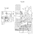
- FIG. 4a1 illustrates a part of the primary impeller 2 which is assigned to a gutter 26 which is arranged in a region which lies between the inside D IS and the outside diameter D AS of the blading 44.
- the gutter 26 extends in the radial direction into an area which is in the area of the working space 4 or at its height.
- the connection between the storage space 40 and the working space 4 takes place via an obliquely designed through opening 27.1, which extends from the paddle wheel base 36 to the outside of the paddle wheel 37, which at the same time forms an outer boundary surface for the gutter 26.
- the gutter 26 is formed only by means of an annular component 38.
- the dynamic pressure tube 32.2 extends through the annular component 38 and projects into the storage space 40 formed by the gutter 26.
- the dynamic pressure pipe 32.2 is designed such that the opening area 41.2 is arranged in the installed position in the radial direction above the passage through the annular element 38.
- the part 42.2 carrying the opening area preferably extends essentially parallel to an operating center mirror 43 which is set in the storage space 40.
- FIG. 4a2 illustrates a view I-I corresponding to FIG. 4a1. from that the course of the part 42.2 carrying the opening area 41.2 seen. Furthermore, it can be seen that due to the orientation of the Opening area 41.2 in the circumferential direction with changing operating modes, i.e. Reversing a second dynamic pressure pipe 32.1 is required, the Opening area 41.1 in the opposite direction to Opening area 41.2 extends in relation to the circumferential direction.
- the two Pitot tubes 32.1 and 32.2 are assigned to them Line sections 47 and 48 via a check valve 46 with a common line 49 connected.
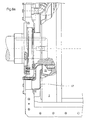
- FIG. 4b1 shows an embodiment of a gutter which is arranged in the radially inner region of the primary impeller 2.
- the gutter 26 is arranged in an area of the blading 44 of the primary blade wheel 2 which is located in the radial direction.
- the storage space is limited by the inner diameter d R of the gutter 26, the outer contour 37 of the primary impeller 2, and the surfaces 29 of the components connected in a rotationally fixed manner to the primary impeller 2.
- the operating medium level 43 is here at the level of the opening area 41.2. of the pitot tube 32.2.
- the dynamic pressure tube 32.2 is also designed here in such a way that the opening area 41.2 is aligned in the circumferential direction and is immersed in the operating medium located in the storage space 40.
- the dynamic pressure tube 32 is arranged according to the desired degree of filling to be limited at a certain distance from the coupling axis A.
- the dynamic pressure tube 32.2 is arranged above the coupling axis A.
- FIG. 5a and 5b illustrate a further embodiment of the Pitot tube 32.
- the component supporting the pitot tubes 32.1 and 32.2 55 is attached to the housing.
- FIG. 5b illustrates a view III-III according to Figure 5a.
- Figures 3 to 5 only illustrate the design of the Gutter and through openings. Other ways with which the same function can be performed are also conceivable. According to the Design of the coupling with one or more work spaces can be done in the former case the gutter either the primary paddle wheel or the Secondary paddle wheel or a shell are assigned in the latter case, however, for constructional reasons only that Primary blade.
- the gutter itself is a separate component executed or as a component with the appropriate paddle wheel.
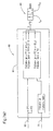
- FIGS. 7a to 7d illustrate in a simplified representation on the basis of control schemes the use of the dynamic dynamic pressure value p dynamic determined by means of the dynamic pressure generation or detection device or of a pressure signal generated with this device for controlling an actuating device for influencing the supply of operating fluid to the work space 4 or 5 hydrodynamic coupling 1.
- FIGS. 7a1 and 7a2 illustrate on the basis of a block diagram the general possibility of using the dynamic dynamic pressure value p dynamic provided by means of the dynamic pressure generating or measuring device / 2v 2 .
- a control device 60 has at least one control device 61, which in each case comprises at least one first input 62 and one first output 63.
- the first input 62 can be coupled at least indirectly to the dynamic pressure generating or detection device, while the first output 63 is coupled at least indirectly to the device for influencing the feed quantity to the work space.
- This device is designed here as a valve device, preferably in the form of a 3/2-way valve and is designated by the reference number 64.
- a pressure signal is fed to the control device 61 via the first input 62.
- This pressure signal is formed either by the first pressure value p 1 or by the second increased pressure value p 2 .
- manipulated variable Y for controlling the device for influencing the feed quantity to the working space of the hydrodynamic coupling is formed at output 63. If the first pressure value p 1 is present at the input 62, the manipulated variable formed is zero, ie no signal is generated to control the device for influencing the feed quantity to the working space of the hydrodynamic clutch 64.
- a manipulated variable Y is output at the output 63, which causes the device 64 to influence the inflow quantity to the working space of the hydrodynamic Coupling takes a position that the inlet to the work area, and thus the flow of resources to the work area, is interrupted. Since these devices for influencing the inflow quantity are generally valve devices, the manipulated variable Y is output in a form which is effective on the actuating devices 65 of the device for influencing the inflow quantity to the working space of the hydrodynamic coupling.
- the actuation devices 65 can be acted upon electrically, pneumatically, hydraulically or mechanically.
- the manipulated variable Y is therefore to be formed in accordance with the selection of the actuating device 65.
- the device for influencing the feed quantity to the working space of the hydrodynamic coupling 64 is preferably actuated electromagnetically.
- the valve device 64 is designed with a reset device, for example in the form of a spring device, which sets the switching position II 21 on the valve device 64 due to its restoring force when the force applied to the actuating device 65 is reduced.
- a manipulated variable Y is then output, which interrupts the power supply.
- the entire control of the valve device 64 is preferably carried out by the control device 60.
- the control device 61 is assigned a further second input 75 for specifying a signal for filling the working space of the hydrodynamic coupling.
- the second input 75 can be coupled to a device for specifying a signal for filling the hydrodynamic coupling. If a signal is present at the second input, which is directed at least indirectly to a desired filling of the clutch, a manipulated variable Y is output at the output, which is used to actuate the valve device 64, in particular to apply an actuating force to the actuating device in such a way that the valve device Line at least partially releases the filling of the work area.
- the manipulated variable Y is formed in such a way that the valve device assumes a switch position which reduces or interrupts the supply of operating fluid to the work area.
- the control device 61 can be designed as a separate control device become.
- the individual control functions can for example by means of a microprocessor control or by means of can be implemented accordingly switching elements to be coupled.
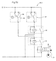
- FIG. 7b illustrates, using a control scheme for a pressure switch connection, the minimal equipment of the control device 60.1 required to achieve the object according to the invention.
- This includes two pressure switch devices, a first pressure switch device 66 and a second pressure switch device 67, which are used for different directions of rotation of the rotor parts of the hydrodynamic clutch 1.
- the first pressure switch device 66 is provided, for example, for the left-hand direction of rotation, while the second pressure switch device 67 can only be activated in the right-hand direction of rotation.
- the pressure switch devices are coupled to a voltage source and form the connecting links to the actuating device 65 of the device 64 for influencing the feed quantity to the working space of the hydrodynamic coupling, here in the form of a 2/2-way valve.
- Both pressure switch devices 66 and 67 are arranged in series. Their respective switching elements 68 and 69 each enable a connection between a voltage source (not shown in detail here) and the actuating device 65 of the device for influencing the feed quantity to the working space of the hydrodynamic coupling 64 in the first switching position 1/2 or 1/2 a second switch position 1/4 or 1/4 this connection is interrupted.
- the switching devices 68 and 69 are thereby in dependence of the detection device or by means of the Stauller Wegungs- 32 detected dynamic pressure p effort of the second elevated pressure value p 2 corresponds actuated.
- the dynamic pressure p can be used dynamically directly or only indirectly to act on the switching elements 68 and 69.
- the device for influencing the feed quantity to the working space of the hydrodynamic clutch likewise has at least two switching positions, a first switching position 80 and a second switching position 81.
- first switching position 80 a not shown here in detail, Operating fluid supply device coupled to the work space - or the feed line 82 - to the work space of the hydrodynamic coupling.
- second switch position 81 the flow of resources between the resources supply device and the feed line 82 is interrupted.
- the solution according to the invention is based on a so-called black-and-white principle, that is to say essentially only two different pressure values or pressure value states are determined for the two filling degree states, these two pressure value states can be actuated by the switching elements 68 or 69 of the pressure switching devices 66 or 67 are transmitted. Only when a dynamic dynamic pressure value p dynamic is detected is the corresponding pressure switching device actuated in such a way that the switching elements 68 or 69 are brought into the respective switching positions 1/2 or 1/2 or 1/4 or 1/4, which form a connection between one
- the voltage source and the actuating device 65 of the device for influencing the feed quantity to the working space of the hydrodynamic clutch 64 enable or interrupt such that it assumes either the first switching position 80 or the second switching position 81.
- FIG. 7c illustrates an embodiment of a control device 60.2 corresponding to Figure 7b, but with an additional Backup option.
- the basic structure corresponds essentially to that in of Figure 7b described.
- the individual switches 68 and 69 of the individual pressure switch devices 66 and 67 by means of the Back pressure generation or detection device 32 generated back pressure or a pressure value proportional to this.
- the device 64 also becomes the rotor part of the hydrodynamic coupling for influencing the feed quantity to the working space of the hydrodynamic Coupling 64, or its actuating device 65 is acted upon.
- a third switch 85 is provided which is used to interrupt the electrical connection between the actuator 65 and the individual pressure switch devices 66 and 67 is used.
- This additional Switch 85 is controlled via a locking device 86.
- the Control is preferably electrical, but can also be mechanical, done hydraulically or pneumatically. This additional locking means the locking element 86 allows a short circuit on the Device for influencing the amount of operating fluids to the work area to avoid.
- FIG. 7d shows a further development of the minimal design illustrated in FIG. 7b for realizing the function according to the invention.
- the control device is designated 60.3 here.
- this also comprises two pressure switch devices 66 and 67, respectively.
- these two pressure switch devices are each assigned to a direction of rotation of the rotor parts of the hydrodynamic clutch 1.
- the first pressure switch device 66 is designed for a rotation direction on the left and the second pressure switch device 67 for a rotation direction on the right.
- these two pressure switch devices 66 and 67 are each coupled either to a separate dynamic pressure pipe oriented for the corresponding direction of rotation, or generally to the dynamic pressure generating or detecting device.
- the coupling is essentially limited to the fact that the actuating signal for actuating the switching elements 68 and 69 of the two pressure switching devices 66 and 67 acts directly on the switches 68 and 69.
- the pressure signal can dynamically correspond to the dynamic dynamic pressure p generated or be proportional to it.
- a variable which is at least proportional to the dynamic pressure and which can have a different dimension acts on the switches 68 and 69.
- the loading can always be done directly or indirectly via other intermediate sizes.
- Each of the two pressure switch devices 66 and 67 enables the Switching elements 68 and 69 an adjustment or a loosening of the connection the actuating device 65 of the device for influencing the Resource supply to the working space of the hydrodynamic coupling 64 with a voltage source not shown here in detail.
- the connection is in the switching position 1/2 or 1/2 of the two pressure switch devices achieved. Decoupling takes place in the other switching position 1/4 or 1/4 between the voltage supply device and the actuating device 65 instead of.
- a delay device in the form of a delay relay 90 or 91 is connected downstream of each of the two pressure switches 66 and 67.
- the pressure switching device 66, the delay relay 91 and the pressure switching device 67, the delay relay 90 are assigned and connected downstream.
- the individual delay relays 90 and 91 are designed such that they prevent the clutch from overfilling if the signal for the second pressure value p 2 drops out briefly.
- This time period can be freely selected or can be predefined according to the design of the delay relays 90 and 91.
- a so-called delay period of 0 to 5 seconds is preferably selected.
- the switching element 68 is brought into the switching position 1/4.
- the pressure switching device 66 switches off the delay relay 91.
- FIGS. 7b to 7d in particular the Individual tax tasks can also be carried out using a Microprocessor control can be realized.
- other conversion units for converting the dynamic dynamic pressure characterizing size into one size corresponding to the dimension for controlling the actuating device 65 is converted.
- the specific design and assignment different structural components to realize the The functions mentioned are at the discretion of the individual specialist.
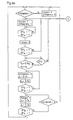
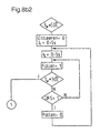
- FIG. 8a illustrates the possible on the basis of a signal flow diagram Procedure for setting a defined filling or one predeterminable degree of filling by adjusting the position of the Back pressure pump of the hydrodynamic clutch, especially during commissioning.
- the individual names in the flow chart are in the following legend to Figures 8a and 8b explained.
- the decisive factor is whether there is a filling command, ie a signal to control the device 64 for influencing the feed quantity to the working space of the hydrodynamic coupling. if this signal is given, the device for influencing the inflow quantity is controlled in such a way that it connects, for example, an operating medium supply unit in the form of a tank to the work space or the feed line to the work space of the hydrodynamic coupling 1. The drain from the working area of the hydrodynamic coupling is closed. During the filling process it is now checked whether there is a signal for a second increased pressure value p 2 from the filling level condition detection device, ie the filling level detection UFS in the storage space is addressed.
- a filling command ie a signal to control the device 64 for influencing the feed quantity to the working space of the hydrodynamic coupling.
- the signals of both devices are preferably monitored for different directions of rotation of the rotor parts of the hydrodynamic coupling. If only the first pressure value p 1 is determined, ie the fill level detection has not responded, the opening area of the dynamic pressure generation or detection device is in the resource-free space, the filling process is continued. If there is a signal for the second increased pressure value p 2 , ie if the level detection ÜFS responds, the device for influencing the feed quantity to the working space of the hydrodynamic coupling is activated and the supply of operating fluid to the working space is interrupted immediately, usually by closing the filling valve. After the interruption, the level is monitored further.
- the level detection device does not give a signal, ie if only the first pressure value p 1 is determined, the filling is continued.
- the second pressure value p 2 is detected, that is to say when the degree of filling is identified, which corresponds to the maximum permissible degree of filling, a further check is carried out to determine whether the speed n 2 of the individual rotor parts, in particular the primary blade wheel functioning as a pump impeller, has already exceeded a certain predeterminable speed which preferably corresponds to the speed from which the degree of filling state detection is most likely to work error-free.
- a device for influencing the outlet from the hydrodynamic coupling is activated. This device can be a valve in the outlet or in the drain line from the working space of the hydrodynamic coupling. However, it is also conceivable to assign the drain line to the work area via an intermediate coolant circuit.
- FIG. 8b illustrates the procedure using a signal flow diagram for setting one according to the position of the dynamic pressure pump predefined, freely selectable filling levels in a coupling version with volumetric equipment exchange.
- the hydrodynamic clutch 1 has Primary impeller 2 and a secondary impeller 3.
- the primary impeller acts as an impeller, the secondary impeller as Turbine wheel. Form the primary impeller and the secondary impeller at least one toroidal working space 4 with each other.
- the operating medium flows between the bladed parts Primary and secondary paddle wheel in the work area 4 around. This upheaval is also known as the so-called work cycle.
- a circuit 91 assigned to the circulation of Operating equipment is used during continuous operation.
- This circuit 91 are In each case an inlet line 92 and an outlet line 93 are assigned.
- the Inlet line 92 and outlet line 93 are optionally the circuit can be activated separately or together.
- a first switching valve 94 which is a coupling between drain line 93 and circuit 91, and another Switching device 95, which connects or decouples the feed line 92 to the circuit 91.
- the first switching device 94 is in the form of a 3/2-way valve executed, the second switching device 95 is at least as a 2/2-way valve educated.
- circulating equipment is about from the work area Openings on the paddle wheels in the interior of the clutch housing or but one that emerges with the paddle wheels with rotating rotors Resources.
- the drain line 96 from the working space 4 of the hydrodynamic Coupling is a device for detecting the temperature in the circuit 91 intended. According to the determined temperature value, which one should not exceed a predetermined target value, a decision is made as to whether Resources from the circuit 91 against resources less Temperature to be exchanged. If the permissible is exceeded Temperature in the drain line 96, the first switching device 94, i.e. the 3/2-way valve, so that this is a first Switch position I assumes, in which the outlet line 96 with the Drain line 93 is coupled. This means that the equipment that is in the Circuit 91 would otherwise flow around for cooling purposes, at least partly from circuit 91 and thus also from the working circuit. This equipment must be replaced with new equipment.
- the 2/2-way valve 95 is in a first switching position 95.1 spent, in which the feed line 92 is coupled to the circuit 91.
- the feed line 92 is coupled to the circuit 91.
- the first switching device 94 has a further second switching positions II on. In the second switch position II, this becomes the work area Leaked resources in the circuit 91, which is then closed The circuit functions and is returned to the work area 4.
- the drain valve is then opened in accordance with signal flow diagram 8b1 and, after a certain adjustable time t 5 , the valve in the inlet to the working space of the hydrodynamic clutch is also opened.
- the temperature T is monitored further. If this is lower than a permissible temperature T perm.
- the degree of filling can be set in accordance with the procedure as described in FIG. 8a.
- the interface is 1. If the range of the permissible temperature T perm is not reached and a response of the fill level detection device is detected at the same time, the fill valve is closed and the emptying process is continued.
- FIG. 9 the diagrams for the starting process show the Operating modes of the facility for influencing the Resource supply quantity in the working area of the hydrodynamic Coupling, the drain valve, the drive speeds and Level detection entered over time. These relationships correspond to those described in FIG. 8a on the basis of the signal flow diagram. From this diagram it can be seen that the device for influencing the supply volume to the working space of the hydrodynamic coupling, i.e. the Filling valve is open until the level detection the second indicates increased pressure value. Since the level detection is a so-called black and white circuit, it can be assumed that only the two states 0 and 1 are taken into account. Furthermore, can be seen that when the second pressure value is reached on the Back pressure generating device, the filling valve is closed.
- the level detection indicates a condition during further operation that corresponds only to a partial filling
- the filling valve is accordingly affects that a refill takes place in the work area.
- the level detection continues to be the maximum permissible filling level is displayed. From this diagram is further can be seen that the outlet from the working area of the hydrodynamic Coupling, especially the drain valve defined in the strategy Fill level setting are included.
- a Fill level shows which is the maximum allowable fill level corresponds to a targeted temporary opening of the drain valves in the outlet the working space of the hydrodynamic clutch instead.
- Valve devices are made according to the application. Preferably however, multi-way valves are used. These can also be stepless be operable.
Landscapes
- Engineering & Computer Science (AREA)
- General Engineering & Computer Science (AREA)
- Mechanical Engineering (AREA)
- Hydraulic Clutches, Magnetic Clutches, Fluid Clutches, And Fluid Joints (AREA)
Description
Im stationären Zustand befindet sich immer eine konstante Menge Betriebsmittel in der Kupplung und im Kühlkreislauf. Diesem Kreislauf wird keine Flüssigkeit zugeführt oder entnommen. Eine Erhöhung oder Verminderung der Drehzahl der Arbeitsmaschine wird erzielt, indem der Kupplung Betriebsmittel zugeführt oder entnommen wird. Zu diesem Zweck sind den Arbeitsräumen des weiteren eine Zulaufleitung oder -kanal und ein Ablauf bzw. eine Ablaufleitung- oder Kanal zum Zweck des Befüllens und Entleerens zugeordnet. Die Zu- und die Ablaufleitung sind mit einer externen Betriebsmittelversorgungsanlage, beispielsweise in Form eines Betriebsmitteltanks, gekoppelt. Die Zuordnung der Zu- und Ablaufleitungen zu den Arbeitsräumen kann separat vom Kühlkreislauf oder aber unter Nutzung der Leitungen bzw. Kanäle des Kühlkreislaufes erfolgen.

Da in einem Bereich zwischen unbefüllten Zustand der hydrodynamischen Kupplung und dem maximalen Füllungsgrad kein Drucksignal bzw. nur ein sehr geringer Druck erzeugt wird, und erst im Zustand des maximalen Füllungsgrades ein Staudruck entsprechend pdynamisch = (
- Figuren 1a und 1b
- zeigen eine erfindungsgemäße Ausführung einer hydrodynamischen Kupplung mit Überfüllschutz am Beispiel einer Kupplung mit zwei Arbeitskreisläufen und ein Diagramm zur Verdeutlichung der Funktionsweise des Überfüllschutzes;
- Figuren 2a und 2b
- verdeutlichen anhand einer Ausführung aus dem Stand der Technik und einem Diagramm die Problematik der Verwendung eines im Kreislauf erfaßten Druckwertes zur Ansteuerung des Füllventiles;
- Figuren 3a und 3b
- verdeutlichen erfindungsgemäße Ausführungen einer Fangrinne-Staudruckrohr-Anordnung;
- Figuren 4a bis 4b
- verdeutlichen konkrete Ausführungen erfindungsgemäß gestalteter Fangrinne-Staudruckrohr-Anordnungen;
- Figuren 5a und 5b
- verdeutlichen eine Ausführung des Anschlusses von Leitungen an das Staudruckrohr;
- Figuren 6a und 6b
- verdeutlichen Ausführungen zur Druckwerteerfassung im Bereich der Betriebsmittelfangrinne;
- Figuren 7a bis 7d
- verdeutlichen anhand vereinfachter Steuerschemas die vorrichtungsmäßige Ausgestaltung zur Realisierung der Steuerfunktionen;
- Figuren 8a und 8b
- verdeutlichen anhand von Signalflußbildern die Funktionsweise während des Anfahrvorganges und während der Kühlung am Beispiel der volumetrischen Kühlung im Dauerbetrieb;
- Figur 9
- verdeutlicht anhand von Diagrammen die in der Figur 8a beschriebene Funktionsweise.

Die Figur 4a1 verdeutlicht einen Teil des Primärschaufelrades 2, welcher einer Fangrinne 26 zugeordnet ist, die in einem Bereich angeordnet ist, welcher zwischen dem Innen- DIS und dem Außendurchmesser DAS der Beschaufelung 44 liegt. Die Fangrinne 26 erstreckt sich dabei in radialer Richtung bis in einen Bereich, welcher im Bereich des Arbeitsraumes 4 bzw. auf dessen Höhe liegt. Die Verbindung zwischen dem Stauraum 40 und dem Arbeitsraum 4 erfolgt über eine schräg ausgeführte Durchgangsöffnung 27.1, welche sich vom Schaufelradgrund 36 bis zur Schaufelradaußenseite 37 erstreckt, welche gleichzeitig eine äußere Begrenzungsfläche für die Fangrinne 26 bildet. Die Fangrinne 26 wird lediglich mittels eines ringförmigen Bauteiles 38 gebildet. Das Staudruckrohr 32.2 erstreckt sich dabei durch das ringförmige Bauteil 38 und ragt in den von der Fangrinne 26 gebildeten Stauraum 40 hinein. Das Staudruckrohr 32.2 ist dabei derart ausgeführt, daß der Öffnungsbereich 41.2 in Einbaulage in radialer Richtung oberhalb der Durchführung durch das ringförmige Element 38 angeordnet ist. Der den Öffnungsbereich tragende Teil 42.2 erstreckt sich vorzugsweise im wesentlichen parallel zu einem sich im Stauraum 40 einstellenden Betriebsmitteispiegel 43.
In Einbaulage erfolgt die Anordnung des Staudruckrohres 32 entsprechend des gewünschten zu begrenzenden Füllungsgrades in einem bestimmten Abstand zur Kupplungsachse A. Im dargestellten Fall ist das Staudruckrohr 32.2 oberhalb der Kupplungsachse A angeordnet.

- Füllen = 1:
- Füllventil geöffnet; Zuspeisung v. Betriebsmedium
- Entleeren = 1:
- Entleerventil geschlossen; keine Entnahme von Medium
- ÜFSr = 1:
- Füllstandserkennung angesprochen, Drehrichtung rechts
- ÜFSl = 1:
- Füllstandserkennung angesprochen, Drehrichtung links
- ÜFS = 1:
- Füllstandserkennung angesprochen (links oder rechts)
- n2 ≥ 0,9 nN:
- Abtriebsdrehzahl, bei der die Füllstandserkennung sicher
- n2 ≤ nN
- arbeitet
- Füllbefehl = 1:
- Befehl von der Anlage, die VTK zu füllen
- Füllen = 0:
- Füllventil geschlossen, keine Zuspeisung
- Entleeren = 0:
- Entleerventil offen, VTK wird entleert
- t1 = 0-5 s:
- Taktzeit für Entleeren (Entleeren = 0)
- t2 = 0-5 s:
- Wartezeit (Entleeren = 1)
- t3 = 0-5 s:
- Taktzeit für Füllen ( Füllen = 1)
- t4 = 0-5 s:
- Wartezeit (Füllen = 0)
- t5 = 0-5 s:
- Wartezeit Wassertausch (Füllen = 1)
- T ≥ 50°C (höher?):
- Störung Übertemperatur
- Tzul. ≤ 30° (höher?):
- zul. Temperatur nach Wassertausch
Claims (27)
- Verfahren zur Realisierung eines Überfüllschutzes einer hydrodynamischen Kupplung (1), umfassend wenigstens zwei Schaufelräder (2, 3), die wenigstens einen torusförmigen, mit einem Betriebsmittel befüllbaren Arbeitsraum (4, 5) bilden;
bei welchem der Füllungsgrad über eine, den Füllungsgrad wenigstens mittelbar charakterisierende Größe ermittelt wird und bei Erreichen eines maximalen Füllungsgrades die Betriebsmittelmittelzufuhr unterbrochen wird;
gekennzeichnet durch die folgenden Merkmale:1.1 bei welchem während des Befüllvorganges in einem bestimmten Verhältnis zum Füllungsgrad der Kupplung Betriebsmittel aus dem Arbeitsraum in einen mit dem Arbeitsraum (4, 5) über wenigstens eine Durchgangsöffnung in einem Schaufelrad gekoppelten Stauraum (40) geleitet wird;1.2 bei welchem wenigstens eine Staudruckerzeugungs- bzw erfassungseinrichtung (32, 32.1, 32.2) in den Stauraum (40) eingeführt wird;1.3 bei welchem die Staudruckerzeugungs- bzw. erfassungseinrichtung (32, 32.1, 32.2) gegenüber dem Stauraum derart angeordnet wird, daß1.3.1 in einem ersten Füllungsgradzustand, der einen Füllungsgrad kleiner dem maximalen Füllungsgrad entspricht, kein oder nur ein sehr kleiner erster, über den gesamten ersten Füllungsgradzustand konstanter Druck (p1) mit der Staudruckerzeugungs- bzw. erfassungseinrichtung (32, 32.1, 32.2) erfaßt wird und1.3.2 in einem zweiten Füllungsgradzustand, der einem maximalen Füllungsgrad entspricht, ein zweiter wesentlich größerer Druck (p2) erfaßt wird und dieser zweite Druck wenigstens mittelbar zur Ansteuerung einer Einrichtung (21, 64) zur Unterbrechung der Betriebsmittelzufuhr zum Arbeitsraum (4, 5) genutzt wird, wobei beim Übergang von einem in den anderen Zustand wenigstens ein Signalsprung erzeugt wird. - Verfahren nach Anspruch 1 mit einer Staudruckerzeugungs- bzw. erfassungseinrichtung in Form wenigstens eines Staudruckrohres (32, 32.1, 32.2) mit einem sich in den Stauraum (40) erstreckenden Öffnungsbereich (41.1, 41.2);2.1 bei. welchem lediglich im zweiten Füllungsgradzustand Betriebsmittel im Stauraum (40) durch den Öffnungsbereich (41.1, 41.2) am Staudruckrohr (32, 32.1, 32.2) aufgenommen wird und der dynamische Druck im Staudruckrohr (32, 32.1, 32.2), welcher als zweiter erhöhter Druckwert fungiert, erfasst wird;2.2 bei welchem der zweite erhöhte Druck wenigstens mittelbar als Eingangssignal einer Steuervorrichtung (60, 61) fungiert.
- Verfahren nach einem der Ansprüche 1 oder 2, dadurch gekennzeichnet, daß der maximale Füllungsgrad dem theoretisch maximal zulässigen Füllungsgrad von 100% entspricht.
- Verfahren nach einem der Ansprüche 1 oder 2, dadurch gekennzeichnet, daß der maximale Füllungsgrad durch Einstellung der Position der Staudruckerzeugungs- bzw. erfassungseinrichtung (32, 32.1, 32.2) gegenüber dem Stauraum (40) frei einstellbar ist.
- Verfahren nach einem der Ansprüche 1 bis 4, dadurch gekennzeichnet, daß die Unterbrechung der Betriebsmittelversorgung zum Arbeitsraum (4, 5) zeitlich verzögert zur Erfassung des zweiten erhöhten Druckwertes erfolgt.
- Verfahren nach einem der Ansprüche 1 bis 5, gekennzeichnet durch die folgenden Merkmale:6.1 bei welchem nach Unterbrechung bei Erfassung eines ersten Druckwertes (p1) die Betriebsmittelzufuhr wieder freigegeben wird;6.2 bei weichern bei erneuter Erfassung des zweiten erhöhten Druckwertes (p2) zusätzlich die aktuelle Antriebsdrehzahl oder eine diese wenigstens mittelbar charakterisierende Größe ermittelt und mit einer vorgebbaren Vergleichsgröße verglichen wird, ab welcher eine fehlerfreie Betriebsweise der Füllstandserkennung erfolgt;6.3 bei welchem bei Unterschreitung dieser Antriebsdrehzahl oder der diese wenigstens mittelbar charakterisierenden Größe und lediglich der Anzeige des ersten Druckwertes (p1) der Füllvorgang fortgesetzt wird, während bei Erkennen des zweiten Füllungsgradzustandes der Füllvorgang bis zum Erreichen der Vergleichsgröße fortgesetzt wird;6.4 bei Erreichen der Vergleichsgröße und dem Erkennen des zweiten Füllungsgradzustandes wird der Arbeitsraum (4, 5) der hydrodynamischen Kupplung zeitweise entleert, wobei bei Vorliegen des ersten Druckwertes (p1) der Füllvorgang erneut aktiviert und über eine vorgebbare Zeitdauer vorgenommen wird;6.5 nach Ablauf einer Wartezeit wird wieder das Vorliegen eines ersten (p1) oder zweiten Druckes (p2) geprüft.
- Verfahren nach einem der Ansprüche 1 bis 6, wobei dem Arbeitsraum (4, 5) wenigstens ein Kühlkreislauf (10) zugeordnet ist, gekennzeichnet durch folgende Merkmale:7.1 bei welchem im Kühlkreislauf (10) die aktuelle Temperatur ermittelt wird;7.2 bei welchem bei Überschreitung einer maximal zulässigen Temperatur Betriebsmittel aus dem Kühlkreislauf (10) über eine bestimmte Zeitdauer entleert wird;7.3 bei welchem während oder nach dieser Zeitdauer Betriebsmittel in den Kühlkreislauf (10) eingespeist wird;7.4 bei welchem nach erfolgtem Betriebsmittelaustausch die Temperatur im Kühlmittelkreislauf (10) ermittelt und mit einem weiteren zweiten zulässigen Temperaturwert für den Betriebszustand nach dem Betriebsmitteltausch verglichen wird und bei Abweichung und zusätzlichem Auftreten des zweiten erhöhten Druckwertes (p2) der Füllvorgang abgebrochen und Betriebsmittel erneut entleert wird.
- Hydrodynamische Kupplung zur Durchführung des Verfahrens gemäß einem der Ansprüche 1 bis 7;8.1 mit wenigstens zwei Schaufelrädern, einem Primärschaufelrad (2) und einem Sekundärschaufelrad (3), welche miteinander wenigstens einen, mit Betriebsmittel befüllbaren torusförmigen Arbeitsraum (4, 5) bilden;8.2 dem torusförmigen Arbeitsraum (4, 5) ist wenigstens eine Zufuhrleitung (17, 82) für Betriebsmittel zugeordnet;8.3 dem Arbeitsraum (4, 5) ist eine Einrichtung (32, 32.1, 32.2) zur Erfassung einer den Füllungsgrad wenigstens indirekt charakterisierenden Größe zugeordnet;8.4 die Einrichtung (32, 32.1, 32.2) ist wenigstens mittelbar mit einer Einrichtung (21, 64) zur Beeinflussung der Zulaufmenge zum Arbeitsraum (4, 5) gekoppelt;
gekennzeichnet durch die folgenden Merkmale:-8.5 die Einrichtung(32, 32.1, 32.2) zur Erfassung einer den Füllungsgrad wenigstens indirekt charakterisierenden Größe umfaßt8.5.1 einen, einem Schaufelrad (2, 3) zugeordneten und mit dem Arbeitsraum (4, 5) über wenigstens eine Durchgangsöffnung in einem Schaufelrad gekoppelten Stauraum (40) und8.5.2 eine Staudruckerzeugungs- bzw. erfässungseinrichtung (32, 32.1, 32.2), welche sich in den Stauraum (40) erstreckt, wobei die Zuordnung der Staudruckerzeugungs- bzw. erfassungseinrichtung (32, 32.1, 32.2) zum Stauraum (40) derart erfolgt, daß erst bei einem bestimmten Betriebsmittelstand im Stauraum (40), welcher einem bestimmten maximalen Füllungsgrad entspricht, die Staudruckerzeugungs- bzw. erfassungseinrichtung (32, 32.1, 32.2) Betriebsmittel aufnimmt und der dadurch erfasste dynamische Staudruck als Signal zur wenigstens mittelbaren Ansteuerung der Enrichtung zur Unterbrechung der Zufuhr zum Arbeitsraum (4,5) verwendet wird. - Hydrodynamische Kupplung nach Anspruch 8, dadurch gekennzeichnet, daß der Stauraum (40) von einer, einem Schaufelrad (2, 3) zugeordneten Fangrinne (26) gebildet wird.
- Hydrodynamische Kupplung nach Anspruch 9, dadurch gekennzeichnet, daß die Fangrinne (26) von wenigstens einem separaten, lösbar mit dem Schaufelrad (2, 3) verbindbaren Bauteil (38, 50) gebildet wird.
- Hydrodynamische Kupplung nach Anspruch 9, dadurch gekennzeichnet, daß die Fangrinne (26, 22) vom Schaufelrad (2, 3) gebildet wird.
- Hydrodynamische Kupplung nach einem der Ansprüche 8 bis 11, dadurch gekennzeichnet, daß die Staudruckerzeugungs- bzw. erfassungseinrichtung (32, 32.1, 32.2) in ihrer Position gegenüber dem Stauraum (40) verstellbar ausgeführt ist
- Hydrodynamische Kupplung nach einem der Ansprüche 8 bis 12, dadurch gekennzeichnet, daß die Staudruckerzeugungs- bzw. erfassungseinrichtung in Form wenigstens eines Staudruckrohres (32, 32.1, 32.2) ausgeführt ist.
- Hydrodynamische Kupplung nach Anspruch 13, gekennzeichnet durch die folgenden Merkmale:14.1 das Staudruckrohr (32, 32.1, 32.2) umfaßt wenigsten ein, einen Öffnungsbereich (41.1, 41.2) tragendes Bauteil (42.1, 42.2) zur Aufnahme von Betriebsmittel;14.2 das den Öffnungsbereich tragende Bauteil (42.1, 42.2) ist mit einem, bezogen auf die Kupplungsachse (A) in radialer Richtung wenigstens zum Teil entgegen die Schwerkraftrichtung gerichteten Rohrteil verbunden.
- Hydrodynamische Kupplung nach Anspruch 14, dadurch gekennzeichnet, daß das den Öffnungsbereich tragende Bauteil (42.1, 42.2) im wesentlichen parallel zu einem, sich im Stauraum (40) einstellenden Betriebsmittelspiegel (43) ausgeführt ist.
- Hydrodynamische Kupplung nach einem der Ansprüche 14 oder 15, dadurch gekennzeichnet, daß das den Öffnungsbereich tragende Bauteil (42.1, 42.2) sich in Richtung des Schaufelrades (2, 3) ertreckt.
- Hydrodynamische Kupplung nach einem der Ansprüche 14 oder 15, dadurch gekennzeichnet, daß das den Öffnungsbereich tragende Bauteil (42.1, 42.2) sich in Umfangsrichtung erstreckt.
- Hydrodynamische Kupplung nach einem der Ansprüche 16 oder 17, gekennzeichnet durch die folgenden Merkmale:18.1 der Öffnungsbereich (41.1, 41,2) ist in Umfangsrichtung gerichtet;18.2 für den Reversierbetrieb sind zwei Staudruckrohre (32.1, 32.2) mit einander entgegengesetzt gerichteten Öffnungsbereichen (41.1, 41.2) vorgesehen;18.3 die beiden Staudruckrohre (32.1, 32.2) sind über eine Ventileinrichtung (46) mit einer gemeinsamen Leitung (49) verbindbar.
- Hydrodynamische Kupplung nach einem der Ansprüche 16 oder 17, gekennzeichnet durch die folgenden Merkmale:19.1 der Öffnungsbereich (41.1, 41,2) ist in Umfangsrichtung gerichtet;19.2 für den Reversierbetrieb sind am Staudruckrohr zwei einander entgegengesetzt gerichtete Öffnungsbereiche vorgesehen.
- Hydrodynamische Kupplung nach einem der Ansprüche 14 bis 16, dadurch gekennzeichnet, daß das den Öffnungsbereich (41.1, 41,2) tragende Bauteil vom, bezogen auf die Kupplungsachse (A) in radialer Richtung wenigstens zum Teil entgegen die Schwerkraftrichtung gerichteten Rohrteil gebildet wird.
- Hydrodynamische Kupplung nach einem der Ansprüche 7 bis 20, dadurch gekennzeichnet, daß die Durchgangsöffnungen (27) in radialer Richtung im Bereich des beschaufelten Teiles (44) des Schaufelrades (2, 3) angeordnet sind.
- Hydrodynamische Kupplung nach einem der Ansprüche 7 bis 21, dadurch gekennzeichnet, daß die Durchgangsöffnungen (27, 27.1) in radialer Richtung im Bereich des von der Beschaufelung (44) freien Teiles des Schaufelrades (2, 3) angeordnet ist.
- Hydrodynamische Kupplung nach einem der Ansprüche 7 bis 22, dadurch gekennzeichnet, daß das Primär- und das Sekundärschaufelrad (2, 3) einen Arbeitsraum (4) miteinander bilden.
- Hydrodynamische Kupplung nach Anspruch 23, dadurch gekennzeichnet, daß das Primär- und das Sekundärschaufelrad (2, 3) wenigstens noch einen weiteren Arbeitsraum (5) miteinander bilden.
- Hydrodynamische Kupplung nach einem der Ansprüche 23 oder 24, dadurch gekennzeichnet, daß der Stauraum (40) dem Primärschaufelrad (2) zugeordnet ist.
- Hydrodynamische Kupplung nach Anspruch 23, dadurch gekennzeichnet, daß der Stauraum (40) dem Sekundärschaufelrad (3) zugeordnet ist.
- Hydrodynamische Kupplung nach einem der Ansprüche 7 bis 26, dadurch gekennzeichnet, daß der Stauraum (40) sich in radialer Richtung bis in einen Bereich erstreckt, der auf einem geringeren Durchmesser als den Schaufelradaußenunrfang (DAS) angeordnet ist.
Applications Claiming Priority (5)
| Application Number | Priority Date | Filing Date | Title |
|---|---|---|---|
| DE29700988U | 1997-01-22 | ||
| DE29700988U DE29700988U1 (de) | 1997-01-22 | 1997-01-22 | Hydrodynamische Kupplung |
| DE19706652A DE19706652C2 (de) | 1997-01-22 | 1997-02-20 | Verfahren zum Betreiben einer hydrodynamischen Kupplung und hydrodynamische Kupplung |
| DE19706652 | 1997-02-20 | ||
| PCT/EP1998/000313 WO1998032987A1 (de) | 1997-01-22 | 1998-01-21 | Verfahren zum betreiben einer hydrodynamischen kupplung und hydrodynamische kupplung |
Publications (2)
| Publication Number | Publication Date |
|---|---|
| EP0892894A1 EP0892894A1 (de) | 1999-01-27 |
| EP0892894B1 true EP0892894B1 (de) | 2002-12-11 |
Family
ID=26034124
Family Applications (1)
| Application Number | Title | Priority Date | Filing Date |
|---|---|---|---|
| EP98904110A Expired - Lifetime EP0892894B1 (de) | 1997-01-22 | 1998-01-21 | Verfahren zum betreiben einer hydrodynamischen kupplung und hydrodynamische kupplung |
Country Status (4)
| Country | Link |
|---|---|
| US (1) | US6357229B1 (de) |
| EP (1) | EP0892894B1 (de) |
| AU (1) | AU742604B2 (de) |
| WO (1) | WO1998032987A1 (de) |
Families Citing this family (11)
| Publication number | Priority date | Publication date | Assignee | Title |
|---|---|---|---|---|
| US6564546B2 (en) * | 2000-04-11 | 2003-05-20 | Fb Performance Transmission Inc. | Variable stall control |
| BR0113598A (pt) * | 2000-08-30 | 2003-07-15 | Voith Turbo Kg | Processo para o controle do consumo de potência de uma embreagem hidrodinâmica por meio do controle do grau de enchimento e de uma embreagem hidrodinâmica |
| WO2002018821A1 (de) | 2000-08-30 | 2002-03-07 | Voith Turbo Gmbh & Co. Kg | Verfahren zur drehzahlregelung einer antriebsmaschine |
| US6913437B2 (en) * | 2000-08-30 | 2005-07-05 | Voith Turbo Gmbh & Co. Kg | Hydrodynamic component |
| DE10122258B4 (de) * | 2001-05-07 | 2005-09-29 | Peter Huber | Kupplungseinheit |
| DE102004015706B4 (de) * | 2004-03-29 | 2012-12-06 | Voith Turbo Gmbh & Co. Kg | Hydrodynamische Baueinheit und Verfahren zur Beschleunigung des Befüllvorganges einer hydrodynamischen Baueinheit |
| DE102004059833A1 (de) * | 2004-12-10 | 2006-06-14 | Voith Turbo Gmbh & Co. Kg | Verfahren zum Regeln der maximalen Drehzahl einer Arbeitsmaschine und hydrodynamische Kupplung hierfür |
| ATE441792T1 (de) * | 2005-04-25 | 2009-09-15 | Hoerbiger & Co | Betätigungssteuereinrichtung für die lamellen einer hydraulischen doppelkupplung |
| US7909733B2 (en) * | 2007-12-21 | 2011-03-22 | Caterpillar Inc. | Clutch end-of-fill detection strategy |
| DE102014005399A1 (de) * | 2013-04-24 | 2014-10-30 | Marquardt Mechatronik Gmbh | Anordnung zur Füllstandsmessung |
| DE102019100485A1 (de) * | 2019-01-10 | 2020-07-16 | Voith Patent Gmbh | Verfahren zum Ansteuern einer hydrodynamischen Maschine und hydrodynamische Maschine |
Family Cites Families (7)
| Publication number | Priority date | Publication date | Assignee | Title |
|---|---|---|---|---|
| DE896195C (de) | 1948-10-02 | 1953-11-09 | Basf Ag | Verfahren zur Herstellung von Acetylen durch unvollstaendige Verbrennung von Kohlenwasserstoffen |
| FR1236353A (fr) * | 1958-11-07 | 1960-07-15 | Voith Gmbh J M | Dispositif d'indication de niveau et de commande, notamment pour accouplements hydrauliques |
| GB896195A (en) * | 1959-06-02 | 1962-05-09 | Voith Gmbh J M | Hydraulic turbo couplings |
| US3405524A (en) * | 1967-02-13 | 1968-10-15 | American Radiator & Standard | Liquid level sensing and control means for fluid drives |
| DE3531987A1 (de) | 1985-09-07 | 1987-04-16 | Bergwerksverband Gmbh | Stroemungskupplung mit schnellentleerung und -befuellung |
| DE4224728C2 (de) * | 1992-07-27 | 1998-01-15 | Voith Turbo Kg | Hydrodynamische Kupplung |
| DE19512367A1 (de) * | 1995-04-01 | 1996-10-02 | Voith Turbo Kg | Antriebseinheit für Förderanlagen, insbesondere Bandantriebsanlage |
-
1998
- 1998-01-21 US US09/155,087 patent/US6357229B1/en not_active Expired - Lifetime
- 1998-01-21 WO PCT/EP1998/000313 patent/WO1998032987A1/de not_active Ceased
- 1998-01-21 EP EP98904110A patent/EP0892894B1/de not_active Expired - Lifetime
- 1998-01-21 AU AU62119/98A patent/AU742604B2/en not_active Ceased
Also Published As
| Publication number | Publication date |
|---|---|
| WO1998032987A1 (de) | 1998-07-30 |
| EP0892894A1 (de) | 1999-01-27 |
| AU742604B2 (en) | 2002-01-10 |
| US6357229B1 (en) | 2002-03-19 |
| AU6211998A (en) | 1998-08-18 |
Similar Documents
| Publication | Publication Date | Title |
|---|---|---|
| DE3208100C2 (de) | Tauchschmierung für ein Getriebe | |
| EP1159178B1 (de) | Verfahren zur steuerung einer hydrodynamischen baueinheit und steuervorrichtung | |
| CH661574A5 (de) | In sich geschlossene getriebeanlage mit druckschmierung. | |
| WO1998032987A1 (de) | Verfahren zum betreiben einer hydrodynamischen kupplung und hydrodynamische kupplung | |
| DE19706652C2 (de) | Verfahren zum Betreiben einer hydrodynamischen Kupplung und hydrodynamische Kupplung | |
| EP3504455B1 (de) | Hydrodynamische kupplung | |
| DE10046828A1 (de) | Verfahren zur Steuerung der Leistungsaufnahme einer hydrodynamischen Kupplung durch Füllungsgradsteuerung und eine hydrodynamische Kupplung | |
| EP0090807B1 (de) | Schaltkupplung, die durch einen fliehkraftabhängigen flüssigkeitsdruck betätigbar ist | |
| EP1313963B1 (de) | Vefahren zur Steuerung der Leistungsaufnahme einer hydrodynamischen Kupplung durch Füllungsgradsteuerung und eine hydrodynamische Kupplung | |
| AT391003B (de) | Fluessigkeitskreislauf fuer eine hydrodynamische kupplung | |
| DE19521926C2 (de) | Hydrodynamische Kupplung | |
| DE10327154B4 (de) | Verfahren zur Schmiermittelversorgung von Lagerbaueinheiten einer hydrodynamischen Kupplung und hydrodynamische Kupplung | |
| EP1702170B1 (de) | Kombinierte entlastungs-und schwallschutzvorrichtung für unter druck setzbare betriebsmittelbehälter hydrodynamischer maschinen | |
| EP1456551B1 (de) | Hydrodynamische baueinheit | |
| DE19512367A1 (de) | Antriebseinheit für Förderanlagen, insbesondere Bandantriebsanlage | |
| EP1315916B1 (de) | Verfahren und vorrichtung zur steuerung einer hydrodynamischen kupplung | |
| DE10163486C1 (de) | Hydrodynamische Baueinheit | |
| DE19603148C1 (de) | Verfahren zur Kühlung des Betriebsmittels in Antriebseinheiten für Förderanlagen, insbesondere Kettenförderanlagen und Antriebseinheit | |
| DE102004015706B4 (de) | Hydrodynamische Baueinheit und Verfahren zur Beschleunigung des Befüllvorganges einer hydrodynamischen Baueinheit | |
| WO2000055520A1 (de) | Getriebebaueinheit | |
| DE19713412B4 (de) | Viskokupplung | |
| EP1558860A1 (de) | Hydrodynamische kupplung und anfahreinheit | |
| EP1313961B1 (de) | Hydrodynamische baueinheit | |
| WO2024218081A1 (de) | Kühlsystem für eine lastpunktabhängige kühlung eines rotors einer elektrischen maschine |
Legal Events
| Date | Code | Title | Description |
|---|---|---|---|
| PUAI | Public reference made under article 153(3) epc to a published international application that has entered the european phase |
Free format text: ORIGINAL CODE: 0009012 |
|
| 17P | Request for examination filed |
Effective date: 19980814 |
|
| AK | Designated contracting states |
Kind code of ref document: A1 Designated state(s): DE FR GB IT Kind code of ref document: A1 Designated state(s): FR GB IT |
|
| 17Q | First examination report despatched |
Effective date: 20000714 |
|
| GRAH | Despatch of communication of intention to grant a patent |
Free format text: ORIGINAL CODE: EPIDOS IGRA |
|
| GRAH | Despatch of communication of intention to grant a patent |
Free format text: ORIGINAL CODE: EPIDOS IGRA |
|
| RBV | Designated contracting states (corrected) |
Designated state(s): FR GB IT |
|
| GRAA | (expected) grant |
Free format text: ORIGINAL CODE: 0009210 |
|
| REG | Reference to a national code |
Ref country code: DE Ref legal event code: 8566 |
|
| AK | Designated contracting states |
Kind code of ref document: B1 Designated state(s): FR GB IT |
|
| REG | Reference to a national code |
Ref country code: GB Ref legal event code: FG4D Free format text: NOT ENGLISH |
|
| GBT | Gb: translation of ep patent filed (gb section 77(6)(a)/1977) |
Effective date: 20030310 |
|
| ET | Fr: translation filed | ||
| PLBE | No opposition filed within time limit |
Free format text: ORIGINAL CODE: 0009261 |
|
| STAA | Information on the status of an ep patent application or granted ep patent |
Free format text: STATUS: NO OPPOSITION FILED WITHIN TIME LIMIT |
|
| 26N | No opposition filed |
Effective date: 20030912 |
|
| REG | Reference to a national code |
Ref country code: FR Ref legal event code: PLFP Year of fee payment: 18 |
|
| PGFP | Annual fee paid to national office [announced via postgrant information from national office to epo] |
Ref country code: IT Payment date: 20150127 Year of fee payment: 18 |
|
| PGFP | Annual fee paid to national office [announced via postgrant information from national office to epo] |
Ref country code: FR Payment date: 20150122 Year of fee payment: 18 Ref country code: GB Payment date: 20150121 Year of fee payment: 18 |
|
| GBPC | Gb: european patent ceased through non-payment of renewal fee |
Effective date: 20160121 |
|
| REG | Reference to a national code |
Ref country code: FR Ref legal event code: ST Effective date: 20160930 |
|
| PG25 | Lapsed in a contracting state [announced via postgrant information from national office to epo] |
Ref country code: GB Free format text: LAPSE BECAUSE OF NON-PAYMENT OF DUE FEES Effective date: 20160121 |
|
| PG25 | Lapsed in a contracting state [announced via postgrant information from national office to epo] |
Ref country code: FR Free format text: LAPSE BECAUSE OF NON-PAYMENT OF DUE FEES Effective date: 20160201 |
|
| PG25 | Lapsed in a contracting state [announced via postgrant information from national office to epo] |
Ref country code: IT Free format text: LAPSE BECAUSE OF NON-PAYMENT OF DUE FEES Effective date: 20160121 |