EP0892140A2 - Method of manufacturing a buffer arrangement, especially for vehicle body parts - Google Patents
Method of manufacturing a buffer arrangement, especially for vehicle body parts Download PDFInfo
- Publication number
- EP0892140A2 EP0892140A2 EP98108977A EP98108977A EP0892140A2 EP 0892140 A2 EP0892140 A2 EP 0892140A2 EP 98108977 A EP98108977 A EP 98108977A EP 98108977 A EP98108977 A EP 98108977A EP 0892140 A2 EP0892140 A2 EP 0892140A2
- Authority
- EP
- European Patent Office
- Prior art keywords
- buffer
- component
- buffer arrangement
- extensions
- arrangement
- Prior art date
- Legal status (The legal status is an assumption and is not a legal conclusion. Google has not performed a legal analysis and makes no representation as to the accuracy of the status listed.)
- Granted
Links
Images

Classifications
-
- E—FIXED CONSTRUCTIONS
- E05—LOCKS; KEYS; WINDOW OR DOOR FITTINGS; SAFES
- E05F—DEVICES FOR MOVING WINGS INTO OPEN OR CLOSED POSITION; CHECKS FOR WINGS; WING FITTINGS NOT OTHERWISE PROVIDED FOR, CONCERNED WITH THE FUNCTIONING OF THE WING
- E05F5/00—Braking devices, e.g. checks; Stops; Buffers
- E05F5/02—Braking devices, e.g. checks; Stops; Buffers specially for preventing the slamming of swinging wings during final closing movement, e.g. jamb stops
- E05F5/022—Braking devices, e.g. checks; Stops; Buffers specially for preventing the slamming of swinging wings during final closing movement, e.g. jamb stops specially adapted for vehicles, e.g. for hoods or trunks
-
- E—FIXED CONSTRUCTIONS
- E05—LOCKS; KEYS; WINDOW OR DOOR FITTINGS; SAFES
- E05Y—INDEXING SCHEME RELATING TO HINGES OR OTHER SUSPENSION DEVICES FOR DOORS, WINDOWS OR WINGS AND DEVICES FOR MOVING WINGS INTO OPEN OR CLOSED POSITION, CHECKS FOR WINGS AND WING FITTINGS NOT OTHERWISE PROVIDED FOR, CONCERNED WITH THE FUNCTIONING OF THE WING
- E05Y2900/00—Application of doors, windows, wings or fittings thereof
- E05Y2900/50—Application of doors, windows, wings or fittings thereof for vehicles
- E05Y2900/53—Application of doors, windows, wings or fittings thereof for vehicles characterised by the type of wing
- E05Y2900/536—Hoods
-
- E—FIXED CONSTRUCTIONS
- E05—LOCKS; KEYS; WINDOW OR DOOR FITTINGS; SAFES
- E05Y—INDEXING SCHEME RELATING TO HINGES OR OTHER SUSPENSION DEVICES FOR DOORS, WINDOWS OR WINGS AND DEVICES FOR MOVING WINGS INTO OPEN OR CLOSED POSITION, CHECKS FOR WINGS AND WING FITTINGS NOT OTHERWISE PROVIDED FOR, CONCERNED WITH THE FUNCTIONING OF THE WING
- E05Y2900/00—Application of doors, windows, wings or fittings thereof
- E05Y2900/50—Application of doors, windows, wings or fittings thereof for vehicles
- E05Y2900/53—Application of doors, windows, wings or fittings thereof for vehicles characterised by the type of wing
- E05Y2900/546—Tailgates
Definitions
- the invention relates to a method for producing a stop buffer arrangement according to the preamble of claim 1.
- the expansion sleeve is now by further screwing the screw spread so that it sits axially firmly in the sleeve surrounding it, and by means of a External thread on this sleeve, which with a fastener for the Buffer arrangement cooperates on the inner thread sleeve equipped with a building, the buffer head is moved out again a little, creating a desired preload is achieved between the two components in their closed position.
- a fastener for the Buffer arrangement cooperates on the inner thread sleeve equipped with a building
- This known stop buffer arrangement thus contains functional parts in the buffer arrangement both for the adaptation of the axial position of the buffer head to the respective gap width also for setting a desired preload. This results in a relative complicated structure of the buffer arrangement that is difficult to master in terms of production technology. In particular, solving the two subtasks described with this requires one Arrangement also the production of threads of different pitch senses.
- the invention has for its object a generic method while preserving the advantages of the prior art to create a particularly simple, relative robust construction of the buffer arrangement enables and easy adjustment characterized by the axial position of the buffer head and preload.
- a first essential feature of the invention compared to the discussed state of the Technology is in the separation of measures and means of self-adjustment of the axial Position of the buffer head on the respective gap width on the one hand and for setting the respective required bias on the other hand to see a separation that is common today Trend to summarize the measures and means to solve different Contradicts tasks.
- the sleeve surrounding the expansion sleeve according to claim 7 preferably also means for producing a releasable connection with the one component, for example the tailgate of a motor vehicle.
- Another essential feature of the invention is the fact that for Bias adjustment is a very simple part, namely a stop part appropriate strength or thickness and elasticity, which after performing the Self-adjustment of the axial position of the buffer head to the respective gap width either the other component, for example the opening frame of a vehicle trunk, or on the face of the buffer head with simple means known per se and Handles is set.
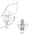
- FIG. 1 If one looks first at FIG. 1, the rear area of one can be seen at 1 Motor vehicle tailgate, the structure of which is of no interest.
- her lower one Sheet 2 is an opening 3, which will be explained later with reference to Figure 3 and serves to partially insert the buffer arrangement 4.
- the buffer arrangement 4 has the elastic buffer head 5, which after completing the stop buffer assembly with Preload on the mushroom or stopper-shaped, serving as a stop part Disc 6 rests, which, in a manner known per se, in the blind rivet 7 on the mounting frame 8 is set.
- the buffer arrangement 4 contains as essential components besides that Buffer head 5, this expansion sleeve 9 with the outer locking profile 10, which in the Outer sleeve 11 is guided with the inner locking profile 12.
- the outer sleeve 11 is, as before is explained with reference to Figures 4 and 5, with means for releasable attachment to the Provide sheet 2. This attachment takes place, as will also be explained below Exploiting the elasticity of the seal 13.
- the screw 14 is somewhat removed from the expansion sleeve 9 unscrewed so that their spread is canceled so far that it does not come out of the Outer sleeve 11 falls, but can still be moved in it.
- the buffer head 5 is pulled out relatively far down, and the tailgate 1 is closed, being now the disc 6 has not yet been inserted.
- Now the screw 14 is screwed deeper into the expansion sleeve 9, so that it is spread and its locking profile 10 with the locking profile 12 of the outer sleeve 11th interacts: The found axial position of the buffer head 5 is fixed.
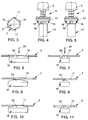
- the Sheet 2 of the tailgate 1 is used on the tailgate side to insert the Buffer arrangement 4 with a predetermined circumferential orientation of the same Opening or recess 3, the two pairs each diametrically opposite has radial extensions 16 and 17, which in this embodiment has an angle of Include 90 ° against each other. As can be seen, the extensions 16 have a larger one Extent of extent than the extensions 17.
- the outer sleeve of the buffer arrangement 4 carries according to the figures 4 and 5 in the same Arrangement and layout of two pairs of radial latching extensions 18 and 19 with the radial Extensions 16 and 17 of the hole pattern according to Figure 3 together a Form bayonet-type holder for the buffer assembly 4.
- the buffer arrangement 4 is according to arrow 20 inserted through the recess 3 until it with its seal 13 (only in the figures 4 and 5 drawn) rests on the top of the sheet 2. While the in Circumferential direction shorter latching extensions 19 in the upward-pointing symmetrical Wear profiles 22, the corresponding profiles 23 of the catch extensions 18 are larger Circumferential extent practically only beveled on one side. It may be appropriate Profile 22 of the latching extensions 19 to execute a little higher, in order to take place now Swiveling movement of the buffer arrangement 4 according to FIGS. 8 and 9 in the area of Latching processes 18 to facilitate.
- the buffer arrangement 30 is constructed in the same way as the buffer arrangement 4 in the previous figures with the only difference that the Buffer head 31 on the end face with the profiled recess 32 for buttoning the Stop part 33 is provided, which replaces the disc 6 and how this only after Self-adaptation of the buffer arrangement 30 to the respective gap width is determined.
- This Construction thus avoids measures on the frame 34 for determining a Stop part.
- the invention is structurally simple and easy to manufacture manageable solution to the problem of creating a bumper buffer arrangement Possibilities for self-adaptation to the respective gap width and setting one predetermined preload.
Landscapes
- Vibration Dampers (AREA)
Abstract
Description
Die Erfindung betrifft ein Verfahren zum Herstellen einer Anschlagpufferanordnung gemäß
dem Oberbegriff des Patentanspruchs 1.The invention relates to a method for producing a stop buffer arrangement according to
the preamble of
Verfahren und Anordnungen dieses Aufbaues, wie sie aus der DE 40 11 186 C2 bekannt sind, bieten den großen Vorteil, daß die Anpassung der axialen Lage des Pufferkopfes der Pufferanordnung an den jeweiligen Spalt zwischen den beiden Bauteilen, also beispielsweise einer Heckklappe eines Kraftfahrzeugs und einem festen Aufbaubereich desselben, weitgehend selbsttätig erfolgt. Wie im einzelnen in der Druckschrift auseinandergesetzt, wird zu diesem Zweck eine Schraube in einer Spreizhülse in eine Position gebracht, in der sie auf die Hülse praktisch keine spreizende Wirkung ausübt; außerdem wird der Pufferkopf etwas aus einer die Spreizhülse aufnehmenden Hülse herausgezogen, so daß bei einem Schließvorgang der beiden Bauteile der Pufferkopf auf eine ihm zugeordnete Anschlagfläche an dem anderen Baute auftrifft und von dieser entsprechend dem Spalt zwischen den beiden Bauteilen zusammen mit der ungespreizten Spreizhülse etwas weiter in die diese umgebende Hülse hineinbewegt wird. Nach erneuter Trennung der beiden Bauteile, also beispielsweise nach Aufklappen der Heckklappe eines Kraftfahrzeugs, wird nunmehr die Spreizhülse durch weiteres Hineinschrauben der Schraube gespreizt, so daß sie axial fest in der sie umgebenden Hülse sitzt, und mittels eines Außengewindes auf dieser Hülse, das mit einer mit Befestigungsmitteln für die Pufferanordnung an dem einen Baute ausgerüsteten Innengewindehülse zusammenwirkt, wird der Pufferkopf wieder etwas herausbewegt, wodurch eine gewünschte Vorspannung zwischen den beiden Bauteilen in ihrer Schließstellung erzielt wird. Würde man auf eine derartige Vorspannung verzichten, so bestünde die Gefahr, daß auch bei einem voll funktionsfähigen Schloß zum Zusammenhalten der beiden Bauteile Klappergeräusche auftreten. Methods and arrangements of this structure, as known from DE 40 11 186 C2 are the great advantage that the adjustment of the axial position of the buffer head Buffer arrangement at the respective gap between the two components, that is for example a tailgate of a motor vehicle and a fixed body area the same, largely done automatically. As detailed in the publication apart, for this purpose a screw in an expansion sleeve in a Brought position in which it has practically no spreading effect on the sleeve; in addition, the buffer head becomes something from a sleeve receiving the expansion sleeve pulled out so that when the two components close, the buffer head opens a stop surface assigned to it strikes on and from the other building corresponding to the gap between the two components together with the unspread Expansion sleeve is moved a little further into the surrounding sleeve. After renewed Separation of the two components, for example after opening the tailgate one Motor vehicle, the expansion sleeve is now by further screwing the screw spread so that it sits axially firmly in the sleeve surrounding it, and by means of a External thread on this sleeve, which with a fastener for the Buffer arrangement cooperates on the inner thread sleeve equipped with a building, the buffer head is moved out again a little, creating a desired preload is achieved between the two components in their closed position. Would you like one dispense with such bias, there is a risk that even with a full functional lock to hold the two components together rattling noises occur.
Diese bekannte Anschlagpufferanordnung enthält also in der Pufferanordnung Funktionsteile sowohl für die Anpassung der axialen Lage des Pufferkopfes an die jeweilige Spaltweite als auch zur Einstellung einer gewünschten Vorspannung. Daraus resultiert ein relativ komplizierter, fertigungstechnisch schwer zu beherrschender Aufbau der Pufferanordnung. Insbesondere erfordert die Losung der beschriebenen beiden Teilaufgaben mit dieser einen Anordnung auch die Herstellung von Gewinden unterschiedlicher Steigungssinne.This known stop buffer arrangement thus contains functional parts in the buffer arrangement both for the adaptation of the axial position of the buffer head to the respective gap width also for setting a desired preload. This results in a relative complicated structure of the buffer arrangement that is difficult to master in terms of production technology. In particular, solving the two subtasks described with this requires one Arrangement also the production of threads of different pitch senses.
Der Erfindung liegt die Aufgabe zugrunde, ein gattungsgemäßes Verfahren unter Wahrung der Vorteile des Standes der Technik zu schaffen, das einen besonders einfachen, relativ robusten Aufbau der Pufferanordnung ermöglicht und sich durch eine einfache Einstellung von axialer Lage des Pufferkopfes und Vorspannung auszeichnet.The invention has for its object a generic method while preserving the advantages of the prior art to create a particularly simple, relative robust construction of the buffer arrangement enables and easy adjustment characterized by the axial position of the buffer head and preload.
Die erfindungsgemäße Losung dieser Aufgabe besteht in den kennzeichnenden Merkmalen des Hauptanspruchs, vorteilhafte Ausbildungen der Erfindung beschreiben die Unteransprüche.The solution to this problem according to the invention consists in the characteristic features of the main claim, advantageous embodiments of the invention describe the Subclaims.
Ein erstes wesentliches Merkmal der Erfindung gegenüber dem diskutierten Stand der Technik ist in der Trennung der Maßnahmen und Mittel zur Selbstanpassung der axialen Lage des Pufferkopfes an die jeweilige Spaltweite einerseits und zur Einstellung der jeweils erforderlichen Vorspannung andererseits zu sehen, eine Trennung, die dem heute üblichen Trend zur Zusammenfassung der Maßnahmen und Mittel zur Lösung verschiedener Aufgaben widerspricht. Daraus resultiert eine wesentliche Vereinfachung der Pufferanordnung insofern, als die die Spreizhülse umgebende Hülse als Außenhülse das äußerste Bauteil der Pufferanordnung bildet, also keine zusätzliche Außenhülse vorhanden ist, die über Gewinde mit einem Außengewinde auf der die Spreizhülse umgebenden Hülse kämmt. Demgemäß trägt die die Spreizhülse umgebende Hülse gemäß Anspruch 7 vorzugsweise auch Mittel zur Herstellung einer lösbaren Verbindung mit dem einen Bauteil, beispielsweise der Heckklappe eines Kraftfahrzeugs.A first essential feature of the invention compared to the discussed state of the Technology is in the separation of measures and means of self-adjustment of the axial Position of the buffer head on the respective gap width on the one hand and for setting the respective required bias on the other hand to see a separation that is common today Trend to summarize the measures and means to solve different Contradicts tasks. This results in a significant simplification of the Buffer arrangement insofar as the sleeve surrounding the expansion sleeve serves as the outer sleeve forms the outermost component of the buffer arrangement, so there is no additional outer sleeve is the thread with an external thread on the sleeve surrounding the expansion sleeve combs. Accordingly, the sleeve surrounding the expansion sleeve according to claim 7 preferably also means for producing a releasable connection with the one component, for example the tailgate of a motor vehicle.
Ein weiteres wesentliches Merkmal der Erfindung ist darin zu sehen, daß zur Vorspannungseinstellung ein sehr einfaches Teil Einsatz findet, nämlich ein Anschlagteil entsprechender Stärke bzw. Dicke und Elastizität, das nach Durchführung der Selbstanpassung der axialen Lage des Pufferkopfes an die jeweilige Spaltweite entweder an dem anderen Bauteil, also beispielsweise dem Öffnungsrahmen eines Fahrzeug-Kofferraumes, oder stirnseitig am Pufferkopf mit einfachen, an sich bekannten Mitteln und Handgriffen festgelegt wird.Another essential feature of the invention is the fact that for Bias adjustment is a very simple part, namely a stop part appropriate strength or thickness and elasticity, which after performing the Self-adjustment of the axial position of the buffer head to the respective gap width either the other component, for example the opening frame of a vehicle trunk, or on the face of the buffer head with simple means known per se and Handles is set.
Zwei Ausführungsbeispiele der Erfindung werden im folgenden für den Fall der Heckklappe eines Kraftfahrzeugs anhand der Zeichnung erläutert. Es zeigen:
Figur 1- einen Längsschnitt durch den hier interessierenden Fahrzeugbereich mit einer Seitenansicht einer ersten Ausführung einer Anschlagpufferanordnung zur Durchführung des erfindungsgemäßen Verfahrens,
Figur 2- einen senkrechten Schnitt durch die Pufferanordnung,
Figur 3- das Lochbild einer Öffnung im Blech des einen Bauteils zum Durchstecken der Pufferanordnung,
die
- Figure 1
- 2 shows a longitudinal section through the vehicle area of interest with a side view of a first embodiment of a stop buffer arrangement for carrying out the method according to the invention,
- Figure 2
- a vertical section through the buffer arrangement,
- Figure 3
- the hole pattern of an opening in the sheet metal of one component for pushing through the buffer arrangement,
Figures 6 to 11 different relative positions of notches on the buffer arrangement and extensions in the hole pattern of the sheet and
FIG. 12 shows a second exemplary embodiment of a stop buffer arrangement suitable for the method according to the invention in longitudinal section corresponding to FIG. 1.
Betrachtet man zunächst Figur 1, so erkennt man bei 1 den hinteren Bereich einer
Kraftfahrzeug-Heckklappe, deren Aufbau im einzelnen nicht interessiert. In ihrem unteren
Blech 2 befindet sich eine Öffnung 3, die später anhand Figur 3 noch zu erläutern ist und die
zum teilweisen Durchstecken der Pufferanordnung 4 dient. Die Pufferanordnung 4 weist den
elastischen Pufferkopf 5 auf, der nach Komplettierung der Anschlagpufferanordnung mit
Vorspannung auf der pilz- oder stopfenartig ausgebildeten, als Anschlagteil dienenden
Scheibe 6 aufliegt, die in an sich bekannter Weise in dem Blindniet 7 am Aufbaurahmen 8
festgelegt ist.If one looks first at FIG. 1, the rear area of one can be seen at 1
Motor vehicle tailgate, the structure of which is of no interest. In her lower one
Gemäß Figur 2 enthält die Pufferanordnung 4 als wesentliche Bestandteile außer dem
Pufferkopf 5 die diesen tragende Spreizhülse 9 mit dem äußeren Rastprofil 10, die in der
Außenhülse 11 mit dem inneren Rastprofil 12 geführt ist. Die Außenhülse 11 ist, wie noch
anhand der Figuren 4 und 5 erläutert wird, mit Mitteln zur lösbaren Befestigung an dem
Blech 2 versehen. Diese Befestigung erfolgt, wie ebenfalls noch erläutert wird, unter
Ausnutzung der Elastizität der Dichtung 13.According to Figure 2, the
Zunächst wird - bei geöffneter Heckklappe - die Schraube 14 etwas aus der Spreizhülse 9
herausgedreht, so daß deren Spreizung so weit aufgehoben ist, daß sie zwar nicht aus der
Außenhülse 11 herabfällt, aber doch in ihr verschoben werden kann. Der Pufferkopf 5 wird
relativ weit nach unten herausgezogen, und die Heckklappe 1 wird geschlossen, wobei jetzt
die Scheibe 6 noch nicht eingesetzt ist. Das bedeutet, daß der Pufferkopf 5 mit seiner nach
unten weisenden Auflagefläche zur Auflage auf dem Blech 15 des Rahmens 8 kommt. Er
wird demgemäß in eine Position nach oben verschoben, die dem jeweiligen Spalt zwischen
den beiden Bauteilen 1 und 8 entspricht. Diese Lage ist strichpunktiert bei 5' in Figur 2
angedeutet. Nunmehr wird die Schraube 14 tiefer in die Spreizhülse 9 hineingeschraubt, so
daß diese gespreizt wird und ihr Rastprofil 10 mit dem Rastprofil 12 der Außenhülse 11
zusammenwirkt: Die gefundene axiale Lage des Pufferkopfes 5 wird fixiert.First, with the tailgate open, the
Erst jetzt wird zur Erzeugung einer vorgegebenen Vorspannung die Scheibe 6 eingesetzt,
so daß beim erneuten Schließen der Heckklappe 1 der Pufferkopf 5, wie in Figur 1 gezeigt,
auf der Scheibe 6 aufliegt. Der Selbstjustierung der axialen Lage des Pufferkopfes 5 in
Abhängigkeit von der jeweiligen Spaltweite zwischen den Bauteilen 1 und 8 einerseits und
der Herstellung und Einstellung einer vorgegebenen Vorspannung andererseits dienen also
bei der Erfindung unterschiedliche Maßnahmen und Einrichtungen, nämlich einerseits die
Pufferanordnung 4 gemäß Figur 2 und andererseits die Scheibe 6 in Figur 1.Only now is the
Zur Erzielung einer besonders einfachen lösbaren Verbindung der Pufferanordnung 4 dem
Blech 2 der Heckklappe 1 dient heckklappenseitig die ein Durchstecken der
Pufferanordnung 4 bei einer vorbestimmen Umfangsausrichtung derselben zulassende
Öffnung oder Ausnehmung 3, die zwei Paare sich jeweils diametral gegenüberliegender
radialer Fortsätze 16 und 17 aufweist, die in diesem Ausführungsbeispiel einen Winkel von
90° gegeneinander einschließen. Wie ersichtlich, haben die Fortsätze 16 eine größere
Umfangserstreckung als die Fortsätze 17.To achieve a particularly simple detachable connection of the
Die Außenhülse der Pufferanordnung 4 trägt gemäß den Figuren 4 und 5 in gleicher
Anordnung und Auslegung zwei Paare radialer Rastfortsätze 18 und 19, die mit den radialen
Fortsätzen 16 und 17 des Lochbildes gemäß Figur 3 zusammen eine
bajonettverschlußartige Halterung für die Pufferanordnung 4 bilden.The outer sleeve of the
Betrachtet man nun die Figuren 6 und 7, so ist gemäß dem Pfeil 20 die Pufferanordnung 4
durch die Ausnehmung 3 hindurchgesteckt, bis sie mit ihrer Dichtung 13 (nur in den Figuren
4 und 5 gezeichnet) auf der Oberseite des Bleches 2 aufliegt. Während die in
Umfangsrichtung kürzeren Rastfortsätze 19 in Richtung nach oben weisende symmetrische
Profile 22 tragen, sind die entsprechenden Profile 23 der Rastfortsätze 18 größerer
Umfangserstreckung praktisch nur einseitig abgeschrägt. Es kann zweckmäßig sein, das
Profil 22 der Rastfortsätze 19 etwas höher auszuführen, um die nun erfolgende
Schwenkbewegung der Pufferanordnung 4 gemäß den Figuren 8 und 9 im Bereich der
Rastfortsätze 18 zu erleichtern.If one now considers FIGS. 6 and 7, the
Diese Schwenkbewegung findet gemäß den Figuren 10 und 11 dann ihr Ende, wenn die
Profile 23 der ![]()
![]()
In dem Ausführungsbeispiel nach Figur 12 ist die Pufferanordnung 30 ebenso aufgebaut wie
die Pufferanordnung 4 in den früheren Figuren mit dem einzigen Unterschied, daß der
Pufferkopf 31 stirnseitig mit der profilierten Ausnehmung 32 zum Einknöpfen des
Anschlagteils 33 versehen ist, das die Scheibe 6 ersetzt und wie diese erst nach erfolgter
Selbstanpassung der Pufferanordnung 30 an die jeweilige Spaltweite festgelegt wird. Diese
Konstruktion vermeidet also Maßnahmen am Rahmen 34 zur Festlegung eines
Anschlagteils.In the exemplary embodiment according to FIG. 12, the
Damit gibt die Erfindung eine konstruktiv einfache und herstellungsmäßig leicht beherrschbare Lösung des Problems der Schaffung einer Anschlagpufferanodnung mit Möglichkeiten zur Selbstanpassung an die jeweilige Spaltweite und Einstellung einer vorgegebenen Vorspannung.Thus, the invention is structurally simple and easy to manufacture manageable solution to the problem of creating a bumper buffer arrangement Possibilities for self-adaptation to the respective gap width and setting one predetermined preload.
Claims (7)
Applications Claiming Priority (2)
| Application Number | Priority Date | Filing Date | Title |
|---|---|---|---|
| DE19730677 | 1997-07-17 | ||
| DE19730677 | 1997-07-17 |
Publications (3)
| Publication Number | Publication Date |
|---|---|
| EP0892140A2 true EP0892140A2 (en) | 1999-01-20 |
| EP0892140A3 EP0892140A3 (en) | 2005-08-17 |
| EP0892140B1 EP0892140B1 (en) | 2008-02-06 |
Family
ID=7836022
Family Applications (1)
| Application Number | Title | Priority Date | Filing Date |
|---|---|---|---|
| EP19980108977 Expired - Lifetime EP0892140B1 (en) | 1997-07-17 | 1998-05-18 | Method of manufacturing a buffer arrangement, especially for vehicle body parts |
Country Status (2)
| Country | Link |
|---|---|
| EP (1) | EP0892140B1 (en) |
| DE (1) | DE59814162D1 (en) |
Cited By (16)
| Publication number | Priority date | Publication date | Assignee | Title |
|---|---|---|---|---|
| DE19855949C1 (en) * | 1998-12-04 | 2000-07-13 | Bayerische Motoren Werke Ag | Estate car tailgate and rear window swings up and down with a buffer at the bodywork edges which can be adjusted for height while the tailgate is closed |
| EP1193090A3 (en) * | 2000-09-29 | 2003-10-29 | DaimlerChrysler AG | Stop buffer |
| EP1482119A1 (en) * | 2003-05-21 | 2004-12-01 | FIAT AUTO S.p.A. | Stopper with removable spacer |
| FR2886329A1 (en) * | 2005-05-27 | 2006-12-01 | Coutier Moulage Gen Ind | Self-adjusting height stop for motor vehicle opening panel such as hood has regulating bush with lengthwise slots forming two or more flexible fingers |
| DE102006012726B4 (en) * | 2006-03-17 | 2008-07-10 | Pass Gmbh & Co. Kg | Buffer arrangement |
| DE102008029519A1 (en) * | 2008-06-21 | 2009-12-24 | Stabilus Gmbh | Attaching device i.e. four-joint hinge, for attaching flap at body of motor vehicle, has force element for supporting initial positioning movement of component, and attached at compression spring and comprising pot-shaped housing part |
| CN102267495A (en) * | 2010-05-18 | 2011-12-07 | 福特全球技术公司 | Stop assembly for hinged body parts |
| EP2031168A3 (en) * | 2007-08-28 | 2012-07-18 | Springfix Befestigungstechnik GmbH | Buffer element |
| DE102012207902A1 (en) | 2012-05-11 | 2013-11-14 | Bayerische Motoren Werke Aktiengesellschaft | Support device for a closed flap of a vehicle, in particular tailgate of a motor vehicle |
| WO2014037369A1 (en) * | 2012-09-07 | 2014-03-13 | Bayerische Motoren Werke Aktiengesellschaft | Stop arrangement for a positon-changeable element, on a vehicle body |
| DE102012215873A1 (en) * | 2012-09-07 | 2014-05-28 | Bayerische Motoren Werke Aktiengesellschaft | Method for setting stop position of e.g. front door of motor car, involves removing measuring unit from stop mounting location, and adjusting and attaching stop element to stop mounting location based on determined distance |
| FR3011869A1 (en) * | 2013-10-14 | 2015-04-17 | Raymond A & Cie | ADJUSTABLE AUTO STRAW BUFFER DEVICE |
| CN107618573A (en) * | 2017-10-24 | 2018-01-23 | 苏州紫荆清远新能源汽车技术有限公司 | A kind of hood and electric car |
| CN107640224A (en) * | 2017-08-31 | 2018-01-30 | 神龙汽车有限公司 | The car boot cover buffering block assembly and attachment structure of characteristics of compact layout |
| CN110080645A (en) * | 2019-05-28 | 2019-08-02 | 上汽通用五菱汽车股份有限公司 | A kind of automobile tail gate is adjustable buffering rubber plug and automobile tail gate |
| CN115354935A (en) * | 2022-08-31 | 2022-11-18 | 阿维塔科技(重庆)有限公司 | Automobile front cover buffer cushion and automobile |
Families Citing this family (2)
| Publication number | Priority date | Publication date | Assignee | Title |
|---|---|---|---|---|
| DE102011101393B4 (en) | 2011-05-13 | 2017-01-19 | Audi Ag | Stop buffer arrangement with a rotary adjustment mechanism and with a rotary locking mechanism and kit for a stop buffer arrangement |
| DE102016202480A1 (en) | 2016-02-18 | 2017-08-24 | Pass Gmbh & Co. Kg | Bump stop arrangement for a vehicle and vehicle with such a stop buffer arrangement |
Citations (1)
| Publication number | Priority date | Publication date | Assignee | Title |
|---|---|---|---|---|
| DE4011186A1 (en) | 1989-04-11 | 1990-10-31 | Volkswagen Ag | Stop for car boot lid - can be positionally adjusted after fitting to lid |
-
1998
- 1998-05-18 DE DE59814162T patent/DE59814162D1/en not_active Expired - Lifetime
- 1998-05-18 EP EP19980108977 patent/EP0892140B1/en not_active Expired - Lifetime
Patent Citations (1)
| Publication number | Priority date | Publication date | Assignee | Title |
|---|---|---|---|---|
| DE4011186A1 (en) | 1989-04-11 | 1990-10-31 | Volkswagen Ag | Stop for car boot lid - can be positionally adjusted after fitting to lid |
Cited By (25)
| Publication number | Priority date | Publication date | Assignee | Title |
|---|---|---|---|---|
| DE19855949C1 (en) * | 1998-12-04 | 2000-07-13 | Bayerische Motoren Werke Ag | Estate car tailgate and rear window swings up and down with a buffer at the bodywork edges which can be adjusted for height while the tailgate is closed |
| EP1193090A3 (en) * | 2000-09-29 | 2003-10-29 | DaimlerChrysler AG | Stop buffer |
| EP1482119A1 (en) * | 2003-05-21 | 2004-12-01 | FIAT AUTO S.p.A. | Stopper with removable spacer |
| FR2886329A1 (en) * | 2005-05-27 | 2006-12-01 | Coutier Moulage Gen Ind | Self-adjusting height stop for motor vehicle opening panel such as hood has regulating bush with lengthwise slots forming two or more flexible fingers |
| DE102006012726B4 (en) * | 2006-03-17 | 2008-07-10 | Pass Gmbh & Co. Kg | Buffer arrangement |
| EP2031168A3 (en) * | 2007-08-28 | 2012-07-18 | Springfix Befestigungstechnik GmbH | Buffer element |
| DE102008029519A1 (en) * | 2008-06-21 | 2009-12-24 | Stabilus Gmbh | Attaching device i.e. four-joint hinge, for attaching flap at body of motor vehicle, has force element for supporting initial positioning movement of component, and attached at compression spring and comprising pot-shaped housing part |
| CN102267495A (en) * | 2010-05-18 | 2011-12-07 | 福特全球技术公司 | Stop assembly for hinged body parts |
| CN102267495B (en) * | 2010-05-18 | 2016-08-03 | 福特全球技术公司 | Braking for rotatable body parts is arranged |
| DE102012207902A1 (en) | 2012-05-11 | 2013-11-14 | Bayerische Motoren Werke Aktiengesellschaft | Support device for a closed flap of a vehicle, in particular tailgate of a motor vehicle |
| WO2013167480A1 (en) | 2012-05-11 | 2013-11-14 | Bayerische Motoren Werke Aktiengesellschaft | Support device for a closed flap of a vehicle, in particular tailgate of a motor vehicle |
| US10132110B2 (en) | 2012-05-11 | 2018-11-20 | Bayerische Motoren Werke Aktiengesellschaft | Support device for a closed flap of a vehicle, in particular tailgate of a motor vehicle |
| WO2014037369A1 (en) * | 2012-09-07 | 2014-03-13 | Bayerische Motoren Werke Aktiengesellschaft | Stop arrangement for a positon-changeable element, on a vehicle body |
| DE102012215873A1 (en) * | 2012-09-07 | 2014-05-28 | Bayerische Motoren Werke Aktiengesellschaft | Method for setting stop position of e.g. front door of motor car, involves removing measuring unit from stop mounting location, and adjusting and attaching stop element to stop mounting location based on determined distance |
| DE102012215873B4 (en) | 2012-09-07 | 2022-09-29 | Bayerische Motoren Werke Aktiengesellschaft | Method for setting a stop position of a variable-position element on a vehicle body |
| FR3011869A1 (en) * | 2013-10-14 | 2015-04-17 | Raymond A & Cie | ADJUSTABLE AUTO STRAW BUFFER DEVICE |
| CN104695792B (en) * | 2013-10-14 | 2017-01-18 | A·雷蒙德公司 | A buffer device having a self-adjusting abutment |
| US9580951B2 (en) | 2013-10-14 | 2017-02-28 | A. Raymond Et Cie | Buffer device having a self-adjusting abutment |
| CN104695792A (en) * | 2013-10-14 | 2015-06-10 | A·雷蒙德公司 | A buffer device having a self-adjusting abutment |
| WO2015055921A1 (en) | 2013-10-14 | 2015-04-23 | A Raymond Et Cie | Buffer device having a self-adjusting abutment |
| CN107640224A (en) * | 2017-08-31 | 2018-01-30 | 神龙汽车有限公司 | The car boot cover buffering block assembly and attachment structure of characteristics of compact layout |
| CN107640224B (en) * | 2017-08-31 | 2019-08-20 | 神龙汽车有限公司 | The car boot cover buffering block assembly and connection structure of characteristics of compact layout |
| CN107618573A (en) * | 2017-10-24 | 2018-01-23 | 苏州紫荆清远新能源汽车技术有限公司 | A kind of hood and electric car |
| CN110080645A (en) * | 2019-05-28 | 2019-08-02 | 上汽通用五菱汽车股份有限公司 | A kind of automobile tail gate is adjustable buffering rubber plug and automobile tail gate |
| CN115354935A (en) * | 2022-08-31 | 2022-11-18 | 阿维塔科技(重庆)有限公司 | Automobile front cover buffer cushion and automobile |
Also Published As
| Publication number | Publication date |
|---|---|
| DE59814162D1 (en) | 2008-03-20 |
| EP0892140B1 (en) | 2008-02-06 |
| EP0892140A3 (en) | 2005-08-17 |
Similar Documents
| Publication | Publication Date | Title |
|---|---|---|
| EP0892140A2 (en) | Method of manufacturing a buffer arrangement, especially for vehicle body parts | |
| DE102006004678B4 (en) | Assembly unit for the fastening eye of a buckle | |
| DE19543830A1 (en) | Plastics panel fastener for vehicle body | |
| DE202006013666U1 (en) | Quick release fastener for connecting first and second component has housing component made of plastic and formed as box profile component which is closed in circumferential direction, with wall sections serving as spring legs | |
| DE60127785T2 (en) | Bushing of two sliding elements | |
| EP3760076A1 (en) | Connecting pin for pieces of furniture | |
| DE60007942T2 (en) | End stop for an extendable body part and method for mounting and adjusting the stop | |
| CH663983A5 (en) | DRIVE ROD FITTING FOR WINDOWS OR DOORS. | |
| DE2000971C3 (en) | Expansion dowels, especially for small loads | |
| EP1072745A1 (en) | Lock fitting for windows or doors | |
| DE10306538A1 (en) | Expanding nut | |
| WO2021052840A1 (en) | Fastening element and component arrangement with fastening element and fastening method | |
| DE19916809A1 (en) | Fastening element for sheet metal parts | |
| DE3024419A1 (en) | Blind or awning ball and socket joint - for crank drives has two=part plastics socket with snap connection | |
| DE102009034584A1 (en) | Fitting for fastening device of clip-like connection in seat belt system in vehicle, has vehicle-sided fastening bolt, and belt strap deflection element connected with fitting, where fitting is fastened at vehicle side via fastening bolt | |
| DE202008007378U1 (en) | screw clip | |
| DE10126006B4 (en) | intent window | |
| EP1507984A1 (en) | Housing comprising a locking device for fixing the same to a carrier plate | |
| EP3574813B1 (en) | Hinge for a toilet seat set | |
| DE19612944A1 (en) | Connecting device between different structural assemblies | |
| EP0791759A1 (en) | Quick-release fastener | |
| DE3517067A1 (en) | Wind deflector arrangement | |
| DE102009037357A1 (en) | Closure arrangement for e.g. front bonnet of motor vehicle, has safety shackle including inner thread and outer thread whose size is larger than that of inner thread in lug-shaped regions of outer thread | |
| DE3729027C2 (en) | ||
| EP1398440A2 (en) | Door hinge for motor vehicles with a door check |
Legal Events
| Date | Code | Title | Description |
|---|---|---|---|
| PUAI | Public reference made under article 153(3) epc to a published international application that has entered the european phase |
Free format text: ORIGINAL CODE: 0009012 |
|
| AK | Designated contracting states |
Kind code of ref document: A2 Designated state(s): AT BE CH CY DE DK ES FI FR GB GR IE IT LI LU MC NL PT SE |
|
| AX | Request for extension of the european patent |
Free format text: AL;LT;LV;MK;RO;SI |
|
| PUAL | Search report despatched |
Free format text: ORIGINAL CODE: 0009013 |
|
| AK | Designated contracting states |
Kind code of ref document: A3 Designated state(s): AT BE CH CY DE DK ES FI FR GB GR IE IT LI LU MC NL PT SE |
|
| AX | Request for extension of the european patent |
Extension state: AL LT LV MK RO SI |
|
| RIC1 | Information provided on ipc code assigned before grant |
Ipc: 7E 05F 5/02 B Ipc: 7E 05F 5/06 A |
|
| 17P | Request for examination filed |
Effective date: 20060217 |
|
| AKX | Designation fees paid |
Designated state(s): DE ES FR GB IT SE |
|
| GRAP | Despatch of communication of intention to grant a patent |
Free format text: ORIGINAL CODE: EPIDOSNIGR1 |
|
| GRAS | Grant fee paid |
Free format text: ORIGINAL CODE: EPIDOSNIGR3 |
|
| GRAA | (expected) grant |
Free format text: ORIGINAL CODE: 0009210 |
|
| AK | Designated contracting states |
Kind code of ref document: B1 Designated state(s): DE ES FR GB IT SE |
|
| REG | Reference to a national code |
Ref country code: GB Ref legal event code: FG4D Free format text: NOT ENGLISH |
|
| REF | Corresponds to: |
Ref document number: 59814162 Country of ref document: DE Date of ref document: 20080320 Kind code of ref document: P |
|
| PG25 | Lapsed in a contracting state [announced via postgrant information from national office to epo] |
Ref country code: ES Free format text: LAPSE BECAUSE OF FAILURE TO SUBMIT A TRANSLATION OF THE DESCRIPTION OR TO PAY THE FEE WITHIN THE PRESCRIBED TIME-LIMIT Effective date: 20080517 |
|
| PG25 | Lapsed in a contracting state [announced via postgrant information from national office to epo] |
Ref country code: SE Free format text: LAPSE BECAUSE OF FAILURE TO SUBMIT A TRANSLATION OF THE DESCRIPTION OR TO PAY THE FEE WITHIN THE PRESCRIBED TIME-LIMIT Effective date: 20080506 |
|
| EN | Fr: translation not filed | ||
| PLBE | No opposition filed within time limit |
Free format text: ORIGINAL CODE: 0009261 |
|
| STAA | Information on the status of an ep patent application or granted ep patent |
Free format text: STATUS: NO OPPOSITION FILED WITHIN TIME LIMIT |
|
| 26N | No opposition filed |
Effective date: 20081107 |
|
| GBPC | Gb: european patent ceased through non-payment of renewal fee |
Effective date: 20080518 |
|
| PG25 | Lapsed in a contracting state [announced via postgrant information from national office to epo] |
Ref country code: FR Free format text: LAPSE BECAUSE OF FAILURE TO SUBMIT A TRANSLATION OF THE DESCRIPTION OR TO PAY THE FEE WITHIN THE PRESCRIBED TIME-LIMIT Effective date: 20081128 |
|
| PG25 | Lapsed in a contracting state [announced via postgrant information from national office to epo] |
Ref country code: GB Free format text: LAPSE BECAUSE OF NON-PAYMENT OF DUE FEES Effective date: 20080518 |
|
| PG25 | Lapsed in a contracting state [announced via postgrant information from national office to epo] |
Ref country code: IT Free format text: LAPSE BECAUSE OF FAILURE TO SUBMIT A TRANSLATION OF THE DESCRIPTION OR TO PAY THE FEE WITHIN THE PRESCRIBED TIME-LIMIT Effective date: 20080206 |
|
| PGFP | Annual fee paid to national office [announced via postgrant information from national office to epo] |
Ref country code: DE Payment date: 20160531 Year of fee payment: 19 |
|
| REG | Reference to a national code |
Ref country code: DE Ref legal event code: R119 Ref document number: 59814162 Country of ref document: DE |
|
| PG25 | Lapsed in a contracting state [announced via postgrant information from national office to epo] |
Ref country code: DE Free format text: LAPSE BECAUSE OF NON-PAYMENT OF DUE FEES Effective date: 20171201 |