EP0891489B1 - Innenläuferzahnradölpumpe mit saug- und drucknierenerweiterungen - Google Patents
Innenläuferzahnradölpumpe mit saug- und drucknierenerweiterungen Download PDFInfo
- Publication number
- EP0891489B1 EP0891489B1 EP97953632A EP97953632A EP0891489B1 EP 0891489 B1 EP0891489 B1 EP 0891489B1 EP 97953632 A EP97953632 A EP 97953632A EP 97953632 A EP97953632 A EP 97953632A EP 0891489 B1 EP0891489 B1 EP 0891489B1
- Authority
- EP
- European Patent Office
- Prior art keywords
- kidney
- shaped
- internal
- rotor gear
- suction
- Prior art date
- Legal status (The legal status is an assumption and is not a legal conclusion. Google has not performed a legal analysis and makes no representation as to the accuracy of the status listed.)
- Expired - Lifetime
Links
- 239000012208 gear oil Substances 0.000 title description 3
- 238000002485 combustion reaction Methods 0.000 claims description 4
- 239000012530 fluid Substances 0.000 claims description 3
- 210000003734 kidney Anatomy 0.000 description 47
- 239000003921 oil Substances 0.000 description 8
- 230000010349 pulsation Effects 0.000 description 4
- 239000011295 pitch Substances 0.000 description 3
- 230000001419 dependent effect Effects 0.000 description 2
- 238000004519 manufacturing process Methods 0.000 description 2
- 206010048469 Kidney enlargement Diseases 0.000 description 1
- 230000002411 adverse Effects 0.000 description 1
- 230000000694 effects Effects 0.000 description 1
- 239000007789 gas Substances 0.000 description 1
- 230000001050 lubricating effect Effects 0.000 description 1
- 239000010687 lubricating oil Substances 0.000 description 1
- 238000005457 optimization Methods 0.000 description 1
- 230000000750 progressive effect Effects 0.000 description 1
Images


Classifications
-
- F—MECHANICAL ENGINEERING; LIGHTING; HEATING; WEAPONS; BLASTING
- F04—POSITIVE - DISPLACEMENT MACHINES FOR LIQUIDS; PUMPS FOR LIQUIDS OR ELASTIC FLUIDS
- F04C—ROTARY-PISTON, OR OSCILLATING-PISTON, POSITIVE-DISPLACEMENT MACHINES FOR LIQUIDS; ROTARY-PISTON, OR OSCILLATING-PISTON, POSITIVE-DISPLACEMENT PUMPS
- F04C15/00—Component parts, details or accessories of machines, pumps or pumping installations, not provided for in groups F04C2/00 - F04C14/00
- F04C15/06—Arrangements for admission or discharge of the working fluid, e.g. constructional features of the inlet or outlet
-
- F—MECHANICAL ENGINEERING; LIGHTING; HEATING; WEAPONS; BLASTING
- F04—POSITIVE - DISPLACEMENT MACHINES FOR LIQUIDS; PUMPS FOR LIQUIDS OR ELASTIC FLUIDS
- F04C—ROTARY-PISTON, OR OSCILLATING-PISTON, POSITIVE-DISPLACEMENT MACHINES FOR LIQUIDS; ROTARY-PISTON, OR OSCILLATING-PISTON, POSITIVE-DISPLACEMENT PUMPS
- F04C2/00—Rotary-piston machines or pumps
- F04C2/08—Rotary-piston machines or pumps of intermeshing-engagement type, i.e. with engagement of co-operating members similar to that of toothed gearing
- F04C2/10—Rotary-piston machines or pumps of intermeshing-engagement type, i.e. with engagement of co-operating members similar to that of toothed gearing of internal-axis type with the outer member having more teeth or tooth-equivalents, e.g. rollers, than the inner member
- F04C2/101—Rotary-piston machines or pumps of intermeshing-engagement type, i.e. with engagement of co-operating members similar to that of toothed gearing of internal-axis type with the outer member having more teeth or tooth-equivalents, e.g. rollers, than the inner member with a crescent-shaped filler element, located between the inner and outer intermeshing members
-
- F—MECHANICAL ENGINEERING; LIGHTING; HEATING; WEAPONS; BLASTING
- F04—POSITIVE - DISPLACEMENT MACHINES FOR LIQUIDS; PUMPS FOR LIQUIDS OR ELASTIC FLUIDS
- F04C—ROTARY-PISTON, OR OSCILLATING-PISTON, POSITIVE-DISPLACEMENT MACHINES FOR LIQUIDS; ROTARY-PISTON, OR OSCILLATING-PISTON, POSITIVE-DISPLACEMENT PUMPS
- F04C2/00—Rotary-piston machines or pumps
- F04C2/08—Rotary-piston machines or pumps of intermeshing-engagement type, i.e. with engagement of co-operating members similar to that of toothed gearing
- F04C2/10—Rotary-piston machines or pumps of intermeshing-engagement type, i.e. with engagement of co-operating members similar to that of toothed gearing of internal-axis type with the outer member having more teeth or tooth-equivalents, e.g. rollers, than the inner member
- F04C2/102—Rotary-piston machines or pumps of intermeshing-engagement type, i.e. with engagement of co-operating members similar to that of toothed gearing of internal-axis type with the outer member having more teeth or tooth-equivalents, e.g. rollers, than the inner member the two members rotating simultaneously around their respective axes
Definitions
- the invention relates to an internal rotor gear oil pump with the features of the preamble of claim 1.
- Internal rotor gear pumps are increasingly used as oil pumps for filling gearboxes or other pumps on the one hand, for lubricating internal combustion engines on the other hand. In all cases there are a. the requirements, one to generate the most uniform possible pulsation-free flow, the effects to minimize cavitation in the pump and the cavitation and pulsation associated with it Reduce noise.
- the invention is directed to Internal rotor gear pumps for oil production according to these requirements improve.
- the oil to be pumped is known pumps by one in the pump housing running suction channel essentially at the level of the tooth engagement between the inner and External rotor in a so-called suction kidney fed as tangentially as possible between the The teeth of the two runners are conveyed and if possible via a so-called pressure kidney tangential pressure channel out of the housing the consumption points fed.
- suction and pressure channels only on one side, mostly for space reasons, the housing side, the Gear pair, while the opposite side closing the delivery chamber of the housing, usually the cover, has a smooth surface towards the inside of the pump.
- the oil flow thus enters the delivery chambers on one side of the gear rotor pair and leaves it on the same side again.
- Such a pump is e.g. B.
- the invention changes those available for suction and pressure in the pump Spaces in such a way that on the inflow and outflow side, or at least the outflow side, opposite Side, usually in the lid, additional kidneys can be arranged in the correspond essentially to the suction and pressure kidneys, but especially from these partly deviate in their radial extension.
- the suction kidneys are rare on both Runner pair designed essentially identically, the pressure kidney on the outflow side opposite side is opposite the end of the suction kidney Direction of conveyance withdrawn.
- the distance is preferably on the inflow / outflow side so large that one tooth of the pair of runners is covered without a kidney is, while the distance on the opposite side is 1.5 to 2 teeth of the rotor pair is.
- the dimension of the covers on the inflow / outflow side the opposite side is usefully dependent on the The speed at which the pump is to work is selected larger or smaller. Surprisingly has been shown that by the relatively simple additional design of the pump housing with kidneys of different sizes on both sides significant reduction in cavitation and thus the resulting Noises as well as the pulsation can be achieved.
- the side opposite the inflow / outflow side Kidneys have no direct connection to the inflow or outflow channels, can be arranged even if this page is about Cover side of the pump.
- the pump cover can namely because of the with the various arrangements of the pumps often only available to a limited extent standing space are usually not widened, and therefore leaves the arrangement of inflow or outflow channels.
- the pump according to the invention can thus can also be used as a replacement for existing pump designs, without that changes would have to be made in the vicinity of the pump. This is of particular importance z. B. when using the pumps as lubricating oil pumps for Internal combustion engines in motor vehicles, where due to the otherwise associated prohibit high expenditure on design changes to the internal combustion engine.
- FIGS. 1 to 5 show the housing and cover of a pump without kidney expansion 3 and 4 the pump design according to the invention also in Top view.
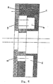
- Fig. 5 shows the pump according to the invention in a section in the plane A-A of Figs. 3 and 4.
- Fig. 1 shows a view of the pump housing 1 with holes for fastening screws 2 and a central bore for the drive shaft 3.
- the Suction kidney 4 and, essentially radially opposite, the pressure kidney 5 are arranged.
- the beginning of the pressure kidney 7 is a tooth division of that in the pump arranged inner rotor gear set (not shown).
- FIG Cover 8 of the pump only for the holes corresponding to the housing Fixing screws and drive shaft on, but no kidneys to hold the oil to be extracted.
- Fig. 3 shows that in the housing area of the pump even with the inventive Execution no changes are required.
- the design of the pump housing is identical to that of the prior art.
- the distance between the end of the suction kidney and the beginning of the pressure kidney is also a tooth pitch of the internal rotor gear set.
- a "blind" suction kidney extension 9 and opposite the pressure kidney 5 also a “blind” pressure kidney extension 10. While the Suction kidney extension 9 in its contours essentially the opposite Suction kidney 4 corresponds and deviates from this only in that it is at an opening opposite to the feed channel, the pressure kidney extension 10 is on the area of the teeth of the inner rotor gear set. The beginning of the expansion of the kidney in the direction of rotation 11 is opposite the beginning of the pressure kidney 7 (cf. Fig. 3) withdrawn by 0.5 to 1 tooth pitch of the inner rotor gear set, so that the distance between the beginning of the pressure kidney extension 11 and the end the suction kidney extension 12 is 1.5 to 2 tooth pitches. The exact measure of The distance between the two boundary lines is dependent on that conveying fluid and the operating conditions of the pump so that a Minimization of cavitation and thus the noise level, the pressure pulsation and the Power consumption is achieved.
- Fig. 5 shows a section through the pump design according to the invention on the Level A-A of FIGS. 3 and 4 the arrangement of the suction and pressure kidney extensions 9 and 10 in the cover 8 of the pump. It is also evident that the kidney enlargement in the outflow area only a part of the delivery space between the Covered teeth of the internal rotor gear set and that the suction and Pressure kidney extensions 9 and 10, compared to the suction and pressure kidneys 4 and 5, have a relatively shallower depth. This can, depending on the operating characteristics the pump, can also be varied for optimization.
- the arrangement of the suction kidney extension 9 is not in all cases the use of appropriate pumps is required. For pumps that are below lower Speeds are running, a suction kidney extension can be omitted.
Landscapes
- Engineering & Computer Science (AREA)
- Mechanical Engineering (AREA)
- General Engineering & Computer Science (AREA)
- Rotary Pumps (AREA)
Description
- 1
- Pumpengehäuse
- 2
- Bohrung für Befestigungsschraube
- 3
- Zentralbohrung für Antriebswelle
- 4
- Saugniere
- 5
- Druckniere
- 6
- Ende der Saugniere
- 7
- Anfang der Druckniere
- 8
- Deckel
- 9
- Saugnierenerweiterung
- 10
- Drucknierenerweiterung
- 11
- Anfang der Drucknierenerweiterung
- 12
- Ende der Saugnierenerweiterung
Claims (5)
- Innenläufer-Zahnradpumpe zum Fördern von Fluiden, vorzugsweise Öl in Getrieben, Pumpen oder Verbrennungsmotoren, mit einem Innenläufer-Zahnradsatz, der in einem Pumpengehäuse (1) angeordnet und durch eine zentrale Welle angetrieben ist, wobei das Pumpengehäuse (1) durch einen an dem Pumpengehäuse und dem Innenläufer-Zahnradsatz anliegenden Deckel (8) abgeschlossen wird, sowie mit mindestens je einer im Pumpengehäuse verlaufenden, in ihren Endbereichen die Zähne des Innenläufer-Zahnradsatzes ganz oder teilweise überdeckenden Zuführ- d.h. Saug- und Abführ- d.h. Druck- Niere (4) bzw. (5), die mit dem Abfluß aus bzw. Zufluß zu dem Verbraucher in Verbindung stehen und sich im Deckel (8) gegenüber den Saug- bzw. Drucknieren (4) bzw. (5) befindenden Saug- bzw. Drucknierenerweiterungen (9) bzw. (10), die mit dem Abfluß aus bzw. Zufluß zu dem Verbraucher nur über die Zwischenräume zwischen den Zähnen des Innenläufer-Zahnradsatzes und die Saug- bzw. Drucknieren (4) bzw. (5) indirekt in Verbindung stehen,
dadurch gekennzeichnet, daß
die Drucknierenerweiterung (10) gegenüber der Saugnierenerweiterung (9) in Förderrichtung zurückgesetzt ist, so daß die Drucknierenerweiterung (10) den Bereich der Zähne des Innenläufer-Zahnradsatzes in geringerem Umfang überdeckt als die gegenüberliegende Druckniere (5). - Innenläufer-Zahnradpumpe nach Anspruch 1,
dadurch gekennzeichnet, daß
die Drucknierenerweiterung (10) in Förderrichtung zunehmend schmälerwerdend gestaltet ist. - Innenläufer-Zahnradpumpe gemäß Anspruch 1,
daduch gekennzeichnet, daß
der Abstand zwischen dem Ende der Saugnierenerweiterung (12) und dem Anfang der Drucknierenerweiterung (11) In Förderrichtung das 0,5 bis 1fache der Zahnbreite des Innenläufer-Zahnradsatzes mehr beträgt als der Abstand zwischen dem Ende der Saugniere (6) und dem Anfang der Druckniere (7) in Förderrichtung. - Innenläufer-Zahnradpumpe nach Anspruch 1,
dadurch gekennzeichnet, daß
die Pumpe im Deckel (8) nur eine Drucknierenerweiterung (10), aber keine Saugnierenerweiterung (9) aufweist. - Innenläufer-Zahnradpumpe nach Ansprüchen 1 bis 4,
dadurch gekennzeichnet, daß
sich die Saug- und Drucknieren (4) bzw. (5), sowie die Zufluß- und Abflußkanäle zu bzw. von ihnen im Deckel (8) der Pumpe, die Saug- und Drucknierenerweiterungen (9) bzw. (10) dagegen im Pumpengehäuse (1) befinden.
Applications Claiming Priority (5)
| Application Number | Priority Date | Filing Date | Title |
|---|---|---|---|
| DE19651950 | 1996-12-16 | ||
| DE19651950 | 1996-12-16 | ||
| DE19747786 | 1997-10-29 | ||
| DE19747786A DE19747786A1 (de) | 1996-12-16 | 1997-10-29 | Innenläuferzahnradölpumpe |
| PCT/DE1997/002931 WO1998027339A1 (de) | 1996-12-16 | 1997-12-16 | Innenläuferzahnradölpumpe mit saug- und drucknierenerweiterungen |
Publications (2)
| Publication Number | Publication Date |
|---|---|
| EP0891489A1 EP0891489A1 (de) | 1999-01-20 |
| EP0891489B1 true EP0891489B1 (de) | 2003-03-12 |
Family
ID=26032199
Family Applications (1)
| Application Number | Title | Priority Date | Filing Date |
|---|---|---|---|
| EP97953632A Expired - Lifetime EP0891489B1 (de) | 1996-12-16 | 1997-12-16 | Innenläuferzahnradölpumpe mit saug- und drucknierenerweiterungen |
Country Status (4)
| Country | Link |
|---|---|
| US (1) | US6089842A (de) |
| EP (1) | EP0891489B1 (de) |
| JP (1) | JP4278714B2 (de) |
| WO (1) | WO1998027339A1 (de) |
Families Citing this family (2)
| Publication number | Priority date | Publication date | Assignee | Title |
|---|---|---|---|---|
| US20040101427A1 (en) * | 2002-11-27 | 2004-05-27 | Visteon Global Technologies Inc. | Gerotor fuel pump having primary and secondary inlet and outlet portings |
| JP2007255369A (ja) * | 2006-03-24 | 2007-10-04 | Jatco Ltd | 変速機のオイルポンプ構造 |
Family Cites Families (4)
| Publication number | Priority date | Publication date | Assignee | Title |
|---|---|---|---|---|
| US3016834A (en) * | 1957-10-07 | 1962-01-16 | Eaton Mfg Co | Rotary pumps |
| US3166018A (en) * | 1963-11-08 | 1965-01-19 | Jr Cresswell E Stedman | Fluid pump body and gear set |
| US3834842A (en) * | 1971-12-06 | 1974-09-10 | Hydraulic Prod Inc | Hydraulic power translating device |
| JP2544835Y2 (ja) * | 1991-02-28 | 1997-08-20 | 株式会社ユニシアジェックス | オイルポンプ |
-
1997
- 1997-12-16 US US09/125,291 patent/US6089842A/en not_active Expired - Lifetime
- 1997-12-16 WO PCT/DE1997/002931 patent/WO1998027339A1/de not_active Ceased
- 1997-12-16 EP EP97953632A patent/EP0891489B1/de not_active Expired - Lifetime
- 1997-12-16 JP JP52718998A patent/JP4278714B2/ja not_active Expired - Fee Related
Also Published As
| Publication number | Publication date |
|---|---|
| JP2000505862A (ja) | 2000-05-16 |
| WO1998027339A1 (de) | 1998-06-25 |
| US6089842A (en) | 2000-07-18 |
| EP0891489A1 (de) | 1999-01-20 |
| JP4278714B2 (ja) | 2009-06-17 |
Similar Documents
| Publication | Publication Date | Title |
|---|---|---|
| DE4343078B4 (de) | Aggregat zum Fördern von Kraftstoff aus einem Vorratstank zu einer Brennkraftmaschine | |
| DE102016120502B4 (de) | Gerotorpumpe für ein fahrzeug | |
| DE19934035A1 (de) | Zahnradpumpe mit innenverzahntem Zahnrad | |
| WO1998017916A1 (de) | Förderpumpe | |
| DE102016120500B4 (de) | Gerotorpumpe für ein fahrzeug | |
| DE10239558B4 (de) | Außenzahnradpumpe mit Druckfluidvorladung | |
| DE4318122A1 (de) | Aggregat zum Fördern von Kraftstoff aus einem Vorratstank zur Brennkraftmaschine eines Kraftfahrzeugs | |
| DE19746505A1 (de) | Innenzahnradpumpe | |
| EP0839283B1 (de) | Ölgedichtete drehschiebervakuumpumpe mit einer ölversorgung | |
| DE4428633A1 (de) | Kraftstoffpumpe zum Zuführen von Kraftstoff zu einem Fahrzeugmotor | |
| DE4322240A1 (de) | Hydraulische Zahnradmaschine (Pumpe oder Motor), insbesondere Innenzahnradmaschine | |
| EP1495227A2 (de) | Hydraulisches pumpenaggregat | |
| DE2048301A1 (de) | Meß- und Spulolpumpe | |
| DE1284156B (de) | Zahnradpumpe zur Speisung von Brennkraftmaschinen mit Brennstoff | |
| EP1042614B1 (de) | Mehrflutige flüssigkeitsringpumpe | |
| DE19749404C1 (de) | Förderpumpe | |
| DE2737659C2 (de) | Flügelzellen-Vakuumpumpe | |
| DE4326505C2 (de) | Peripheralpumpe, insbesondere zum Fördern von Kraftstoff aus einem Vorratstank zur Brennkraftmaschine eines Kraftfahrzeugs | |
| EP0891489A1 (de) | Innenläuferzahnradölpumpe mit saug- und drucknierenerweiterungen | |
| DE19747786A1 (de) | Innenläuferzahnradölpumpe | |
| EP2167821A1 (de) | Pumpengehäuse | |
| WO2017021117A1 (de) | Verdrängerpumpe zur förderung eines fluides für einen verbraucher eines kraftfahrzeuges | |
| DE2714475C2 (de) | Mehrstufige Flüssigkeitsringpumpe | |
| DE2936645B1 (de) | Kreiselpumpe | |
| DE4338677C2 (de) | Pumpe zum Fördern von Fluid, insbesondere als Kraftstoff-Förderaggregat für Kraftfahrzeuge |
Legal Events
| Date | Code | Title | Description |
|---|---|---|---|
| PUAI | Public reference made under article 153(3) epc to a published international application that has entered the european phase |
Free format text: ORIGINAL CODE: 0009012 |
|
| AK | Designated contracting states |
Kind code of ref document: A1 Designated state(s): DE ES FR GB IT NL SE |
|
| 17P | Request for examination filed |
Effective date: 19990308 |
|
| GRAG | Despatch of communication of intention to grant |
Free format text: ORIGINAL CODE: EPIDOS AGRA |
|
| 17Q | First examination report despatched |
Effective date: 20020211 |
|
| GRAG | Despatch of communication of intention to grant |
Free format text: ORIGINAL CODE: EPIDOS AGRA |
|
| GRAH | Despatch of communication of intention to grant a patent |
Free format text: ORIGINAL CODE: EPIDOS IGRA |
|
| GRAH | Despatch of communication of intention to grant a patent |
Free format text: ORIGINAL CODE: EPIDOS IGRA |
|
| GRAA | (expected) grant |
Free format text: ORIGINAL CODE: 0009210 |
|
| AK | Designated contracting states |
Designated state(s): DE ES FR GB IT NL SE |
|
| PG25 | Lapsed in a contracting state [announced via postgrant information from national office to epo] |
Ref country code: NL Free format text: LAPSE BECAUSE OF FAILURE TO SUBMIT A TRANSLATION OF THE DESCRIPTION OR TO PAY THE FEE WITHIN THE PRESCRIBED TIME-LIMIT Effective date: 20030312 Ref country code: IT Free format text: LAPSE BECAUSE OF FAILURE TO SUBMIT A TRANSLATION OF THE DESCRIPTION OR TO PAY THE FEE WITHIN THE PRE;WARNING: LAPSES OF ITALIAN PATENTS WITH EFFECTIVE DATE BEFORE 2007 MAY HAVE OCCURRED AT ANY TIME BEFORE 2007. THE CORRECT EFFECTIVE DATE MAY BE DIFFERENT FROM THE ONE RECORDED.SCRIBED TIME-LIMIT Effective date: 20030312 Ref country code: GB Free format text: LAPSE BECAUSE OF FAILURE TO SUBMIT A TRANSLATION OF THE DESCRIPTION OR TO PAY THE FEE WITHIN THE PRESCRIBED TIME-LIMIT Effective date: 20030312 Ref country code: FR Free format text: LAPSE BECAUSE OF FAILURE TO SUBMIT A TRANSLATION OF THE DESCRIPTION OR TO PAY THE FEE WITHIN THE PRESCRIBED TIME-LIMIT Effective date: 20030312 |
|
| REG | Reference to a national code |
Ref country code: GB Ref legal event code: FG4D Free format text: NOT ENGLISH |
|
| REF | Corresponds to: |
Ref document number: 59709504 Country of ref document: DE Date of ref document: 20030417 Kind code of ref document: P |
|
| PG25 | Lapsed in a contracting state [announced via postgrant information from national office to epo] |
Ref country code: SE Free format text: LAPSE BECAUSE OF FAILURE TO SUBMIT A TRANSLATION OF THE DESCRIPTION OR TO PAY THE FEE WITHIN THE PRESCRIBED TIME-LIMIT Effective date: 20030612 |
|
| NLV1 | Nl: lapsed or annulled due to failure to fulfill the requirements of art. 29p and 29m of the patents act | ||
| GBV | Gb: ep patent (uk) treated as always having been void in accordance with gb section 77(7)/1977 [no translation filed] |
Effective date: 20030312 |
|
| PG25 | Lapsed in a contracting state [announced via postgrant information from national office to epo] |
Ref country code: ES Free format text: LAPSE BECAUSE OF FAILURE TO SUBMIT A TRANSLATION OF THE DESCRIPTION OR TO PAY THE FEE WITHIN THE PRESCRIBED TIME-LIMIT Effective date: 20030930 |
|
| PLBE | No opposition filed within time limit |
Free format text: ORIGINAL CODE: 0009261 |
|
| STAA | Information on the status of an ep patent application or granted ep patent |
Free format text: STATUS: NO OPPOSITION FILED WITHIN TIME LIMIT |
|
| EN | Fr: translation not filed | ||
| 26N | No opposition filed |
Effective date: 20031215 |
|
| REG | Reference to a national code |
Ref country code: DE Ref legal event code: R084 Ref document number: 59709504 Country of ref document: DE |
|
| PGFP | Annual fee paid to national office [announced via postgrant information from national office to epo] |
Ref country code: DE Payment date: 20170130 Year of fee payment: 20 |
|
| REG | Reference to a national code |
Ref country code: DE Ref legal event code: R071 Ref document number: 59709504 Country of ref document: DE |