EP0890967B1 - Einrichtung zum anlassen und schutzen eines Motors - Google Patents
Einrichtung zum anlassen und schutzen eines Motors Download PDFInfo
- Publication number
- EP0890967B1 EP0890967B1 EP98305376A EP98305376A EP0890967B1 EP 0890967 B1 EP0890967 B1 EP 0890967B1 EP 98305376 A EP98305376 A EP 98305376A EP 98305376 A EP98305376 A EP 98305376A EP 0890967 B1 EP0890967 B1 EP 0890967B1
- Authority
- EP
- European Patent Office
- Prior art keywords
- motor
- switch
- resistive heater
- thermostatic element
- temperature
- Prior art date
- Legal status (The legal status is an assumption and is not a legal conclusion. Google has not performed a legal analysis and makes no representation as to the accuracy of the status listed.)
- Expired - Lifetime
Links
Images
Classifications
-
- H—ELECTRICITY
- H01—ELECTRIC ELEMENTS
- H01H—ELECTRIC SWITCHES; RELAYS; SELECTORS; EMERGENCY PROTECTIVE DEVICES
- H01H61/00—Electrothermal relays
- H01H61/002—Structural combination of a time delay electrothermal relay with an electrothermal protective relay, e.g. a start relay
-
- Y—GENERAL TAGGING OF NEW TECHNOLOGICAL DEVELOPMENTS; GENERAL TAGGING OF CROSS-SECTIONAL TECHNOLOGIES SPANNING OVER SEVERAL SECTIONS OF THE IPC; TECHNICAL SUBJECTS COVERED BY FORMER USPC CROSS-REFERENCE ART COLLECTIONS [XRACs] AND DIGESTS
- Y02—TECHNOLOGIES OR APPLICATIONS FOR MITIGATION OR ADAPTATION AGAINST CLIMATE CHANGE
- Y02P—CLIMATE CHANGE MITIGATION TECHNOLOGIES IN THE PRODUCTION OR PROCESSING OF GOODS
- Y02P80/00—Climate change mitigation technologies for sector-wide applications
- Y02P80/10—Efficient use of energy, e.g. using compressed air or pressurized fluid as energy carrier
Definitions
- This invention relates generally to a switch device which is used for starting a motor and more particularly to a motor starting relay and protector employing thermostatic elements.
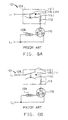
- Switch device 101 comprises a protection device 108 and a resistance element 109 for starting, with one end of the protection device 108 being connected to the power line L1 and the other end connected to a common terminal C of a motor 110.
- One end of resistance element 109 is connected to a start winding terminal S of motor 110 and the other end is connected to ground line L2.
- a main winding and a start winding are provided inside motor 110, the ends of the main winding being connected to common terminal C and the main winding terminal M respectively and the ends of the start winding being connected to common terminal C and the start winding terminal S, respectively.
- a switch circuit 111 and a resistive heater 113 are provided inside the protection device 108 and, prior to starting motor 110, the switch circuit 111 is in an electrically conductive state. Accordingly, the common terminal C is connected, in that state, to power line L1 through switch circuit 111.
- the main winding terminal M is directly connected to ground line L2 and, at the time when motor 110 is to be started, voltage is impressed between power line L1 and ground line L2 with the result that voltage is impressed between the common terminal C and the main winding terminal M and the start winding terminal S.
- Resistance element 109 is a PTC (positive temperature coefficient of resistivity) element having a low resistance at normal or room temperature and which, above an anomaly temperature, increases in resistance as temperature increases.
- Switch 101 has a switch arm 112, a contact 115 and a resistive heater 113 provided in the first switch circuit 111 for the electric current that flows through the main winding and the start winding.
- a bimetal element 114 is provided in close proximity to resistive heater 113 inside protection device 108 so that the electric current which flows through resistive heater 113 generate heat which will heat bimetal element 114 raising the temperature of the bimetal.
- the resistive heater 113 has a low resistance value however, the amount of heat generated by the electric current that flows when motor 110 is started or driven is small and the increase in temperature of bimetal element 114 is small as well.
- bimetal element 114 is heated to a high temperature.
- the side which faces arm 112 is concave facing arm 112 at normal temperatures but, if it is heated to an actuation temperature, e.g., 145°C, by the heat that is supplied from resistance heater 113, it snaps to the opposite, convex configuration facing arm 112 as is shown in Fig. 6(b), thereby raising arm 112 and bringing contact 115 into an open state.
- an actuation temperature e.g., 145°C
- US 2,158,288 describes a pair of thermally controlled switches for starting alternating current motors and for protecting the same against overloads.
- a normally closed motor starting switch is provided with a first thermostatic element which is arranged to change configuration at a given temperature to open said switch upon establishment of power connections for the motor.
- a normally closed motor protection switch is provided with a second thermostatic element which is arranged to change configuration at a given temperature to open said motor protection switch to interrupt the power connections of said motor upon a predetermined overload of said motor.
- a main resistive heater is disposed in a heat conductive relationship with the first and second thermostatic elements.
- An auxiliary resistive heater is disposed in a heat conductive relationship with the first thermostatic element only. In normal use, the auxiliary heater triggers the opening of the motor starting switch and the main heater keeps the motor starting switch open and triggers the opening of the motor protection switch in an overload condition.
- An object of the present invention is the provision of a device which eliminates the prior art limitations described above. Another object of the invention is the provision of a switch device having a small number of parts and a lower cost of installation. Yet another object is the provision of a switch device whose operating efficiency is high and at the same time is capable of supplying a large electric current to the start winding.
- the present invention provides a combination motor starting relay and motor protector apparatus comprising:
- the first and second switch circuits have a contact and a thermostatic element and the first and second resistive heaters are provided, with the thermostatic elements of the first and second switch circuits being actuated when heated to the actuation temperature and the contact of each switch circuit being switched from the closed state to the open state, the first and second resistive heaters being arranged to generate heat when the electric current flows therethrough. Accordingly, the thermostatic element of the first switch circuit is heated by the first resistive heater but the thermostatic element of the second switch circuit is heated by both the first and second resistive heaters, with a consequence that, even if the amount of heat generated by the first and second resistive heaters is reduced, it becomes possible to raise the temperature of the thermostatic element in the second switch circuit to the actuation temperature.
- the thermostatic element is arranged as to move into closer heat conductive relation with the first resistive heater when the thermostatic element in the second switch circuit is actuated and the contact is switched from the closed state to the open state, the amount of heat that is supplied from the first resistive heater increases after actuation. Even if the heat generation of the second resistance heater ceases, therefore, the thermostatic element in the second switch circuit can maintain its actuated state.
- the switch device that has been explained above, if it is arranged so that the thermostatic element of the first switch circuit is heated to the actuation temperature and is actuated, with its actuated state being maintained even when the heat generation of the first resistive heater ceases, it becomes possible for the first switch circuit to serve as a protection circuit against over-current conditions. If, on the other hand, it is arranged so that, in the case where the thermostatic element of the second switch circuit is heated to the actuation and is actuated, the original shape is reset upon the termination of heat generation of the first and second resistive heaters, the second switch circuit assumes an electrically conductive state prior to starting of the motor but assumes a shut-off state during operation of the motor. Accordingly, it becomes possible for the second switch circuit to serve as a start circuit of the motor.
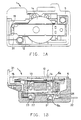
- Switch device 1 serves to start a motor and to provide protection against excess current conditions.
- Switch device 1 comprises a casing 5 made of electrically insulative material such as resin, with a protection device 8 in a switch chamber 8a and a start device 9 in a switch chamber 9a being accommodated therein.
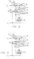
- Motor 10 has a common terminal C, a start winding terminal S and a main winding terminal M, with the common terminal C being connected to the power line L1 through protection circuit 11.
- Start winding terminal S is connected to the ground line L2 through a start device 9 and the main winding terminal M is directly connected to ground line L2.
- Protection device 8 has a first switch circuit 11 and a first resistive heater 13 connected in a series circuit relation.
- first switch circuit 11 The other end of first switch circuit 11 is connected to power line L1 through terminal 31 (Fig. 1(a), 1(b)) that has been fixedly mounted to casing 5 and the other end of first resistive heater 13 is connected to common terminal C through a terminal which is not shown in Figs. 1(a) and 1(b).
- Start device 9 has a second switch circuit 21 and a second resistive heater 23 connected in a series circuit relation.
- the other end of the second switch circuit 21 is connected to ground line L2 through terminal 32 which has been mounted in casing 5 and the other end of second resistive heater 23 is connected to the start winding terminal S through a terminal, not shown in Figs. 1(a) and 1(b).
- the first switch circuit 11 has an arm 12 and a thermostatic element, such as a snap acting bimetal 14, with arm 12 and bimetal element 14 being closely arranged approximately in parallel relationship with each other.
- a thermostatic element such as a snap acting bimetal 14
- arm 12 and bimetal element 14 being closely arranged approximately in parallel relationship with each other.
- One end of arm 12 is provided with an electrical contact 15 and the bimetal element 14 has a dish shape with a concave configuration facing arm 12 at normal or room temperature with contact 15 in a closed state in that shape.
- actuation temperature e.g., 145° C
- the second switch circuit 21 has a cantilever arm 22 comprising a thermostatic element such as a snap acting bimetal element and a contact 25 that has been provided at a free end of the arm 22.
- the shape of the arm 22 is such that it brings the contact 25 to a closed state at normal temperature but is deformed when it is heated to a temperature higher than a selected actuation temperature, e.g., 90° C, at which point the contact 25 is made to assume an open state.
- thermostatic arm element 22 can have a convex configuration (not shown) facing first heater 13 when contact 25 is in a closed state and a concave configuration facing first heater 13 when contact 15 is in the open state with the free end of element 22 moving into closer thermal coupling with heater 13.
- Motor 10 includes a start winding that starts a rotor and a main winding that generates power (the start winding and the main winding are not shown in the drawing).
- the ends of the start winding are connected to the common terminal C and the start winding terminal S, respectively and the ends of the main winding are connected to the common terminal C and the main winding terminal M, respectively.
- the first and second switch circuits 11 and 21 are in an electrically conductive state as shown in Fig. 2.
- voltage is impressed between power line L1 and ground line L2 for the purpose of starting the operation of motor 10, voltage is impressed across both start and main windings.
- bimetal element 14 of the first switch circuit 11 is arranged in close proximity to first resistive heater 13 to be heated by the generation of heat by first resistive heater 13.
- the temperature of bimetal element 14 increases.
- the temperature of bimetal element 14 does not increase to the actuation temperature of 145° C. In this case, therefore, bimetal element 14 is not deformed and contact 15 remains in a closed state.
- a large amount of heat is generated by first resistive heater 13, with a result that bimetal element 14 is thereby heated to the actuation temperature, 145° C.
- arm 12 is pushed up by motion transfer element 12a biased by bimetal element 14 upon actuation, with a result that contact 15 assumes an open state and first switch 11 de-energizes the motor.
- the electric current that has been flowing to motor 10 is interrupted, the electric current that flows to first resistive heater 13 becomes zero, with a consequence that the heat generation of first resistive heater 13 terminates (with no electric current flowing even to second resistive heater 23).
- the temperature of bimetal element 14 and arm 22 of the second switch circuit 21 will decrease.
- arm 22 it is so constructed that, at the time when the temperature has reached a level lower than 70° C, it resets to its original shape and contact 25 is made to assume a closed state.
- Bimetal element can be either manually resettable or can automatically reset upon cooling to a selected reset temperature. Because of this, the contacts are in the closed state after the completion of the operation of motor 10, with motor 10 being prepared to start once again.
- the first switch circuit and the second switch circuit can be arranged closely together in a single housing with a result that the number of parts required will be reduced, thereby lowing the manufacturing cost of the switch device.
- a resistance element 109 shown in Fig. 6 may be used as the second heater. Since the second switch circuit is in a de-energized state after the start-up of the motor, the electric current that flows to the start winding will become zero, thereby making it possible to efficiently operate motor.
- the resistance value of the resistance heater that heats the arm of the second switch circuit can be made small and the starting electric current can be made large, with a consequence that the starting characteristics of the motor can be improved.
Claims (4)
- Kombination aus Motoranlaßrelais und Motorschutzvorrichtung (1), umfassend:dadurch gekennzeichnet, daß:ein Gehäuse (5), das einen Hohlraum bildet;einen Motorschutzschalter (11) mit einem beweglichen Kontaktarm (12), der in und außer Angriff an einem ersten stationären Kontakt (15) bewegbar ist;ein erstes als Schnapper wirkendes thermostatisches Element (14), das temperaturabhängig zwischen einer ersten und einer zweiten Konfiguration bewegbar und so angeordnet ist, daß bei einer Änderung der Konfiguration infolge eines Temperaturanstiegs auf eine Betätigungstemperatur das erste thermostatische Element (14) den beweglichen Kontaktarm (12) außer Angriff mit dem ersten stationären Kontakt (15) drückt;eine erste Widerstandsheizung (13) in wärmeleitender Beziehung mit dem ersten thermostatischen Element (14);einen Motoranlaßschalter (21) mit einem zweiten elektrisch leitenden, als Schnapper wirkenden thermostatischen Element (22), das temperaturabhängig zwischen einer ersten und einer zweiten Konfiguration bewegbar ist und ein freies Ende hat, das als Reaktion auf eine Änderung in der Konfiguration des zweiten thermostatischen Elements in und außer elektrischen Angriff an einem zweiten stationären Kontakt (25) bewegbar ist, wobei das zweite thermostatische Element (22) in wärmeleitender Relation mit der ersten Widerstandsheizung (13) angeordnet ist; undeine zweite Widerstandsheizung (23) in wärmeleitender Beziehung mit dem zweiten thermostatischen Element (22),der Hohlraum eine erste und eine zweite Schalterkammer aufweist, wobei der Motorschutzschalter (11) und die erste Widerstandsheizung (13) in der ersten Schalterkammer angeordnet sind und der Motoranlaßschalter (21) und die zweite Widerstandsheizung (23) in der zweiten Schalterkammer angeordnet sind;die erste und zweite Konfiguration jeweils des ersten (14) und zweiten (22) thermostatischen Elements eine konvexe bzw. eine konkave Konfiguration ist; unddas zweite thermostatische Element (22) auf eine Bewegung in die Konfiguration mit dem freien Ende aus elektrischen Angriff mit dem zweiten stationären Kontakt (25) hin näher an der ersten Widerstandsheizung (13) ist, wodurch die wärmeleitende Beziehung zwischen dem zweiten thermostatischen Element (22) und der ersten Widerstandsheizung (13) verbessert wird.
- Kombination aus Motoranlaß- und Motorschutzvorrichtung nach Anspruch 1, die ferner einen Bewegungsübertragungsstift aufweist, der im Gehäuse (5) zwischen dem beweglichen Kontaktarm (12) des Motorschutzschalters (11) und dem ersten als Schnapper wirkenden thermostatischen Element (14) angeordnet ist, um eine Bewegung vom ersten als Schnapper wirkenden thermostatischen Element (14) zum beweglichen Kontaktarm (12) zu übertragen.
- Kombination aus Motoranlaß- und Motorschutzvorrichtung nach Anspruch 1 oder Anspruch 2, bei der der bewegliche Kontaktarm (12) des Motorschutzschalters (11) in Reihe mit der ersten Widerstandsheizung (13) geschaltet ist und das zweite als Schnapper wirkende thermostatische Element (22) in Reihe mit der zweiten Widerstandsheizung (23) geschaltet ist.
- Kombination aus Motoranlaß- und Motorschutzvorrichtung nach einem der Ansprüche 1 bis 3, bei der die zweite Widerstandsheizung (23) ein PTC-Element ist.
Applications Claiming Priority (3)
| Application Number | Priority Date | Filing Date | Title |
|---|---|---|---|
| JP20075297 | 1997-07-10 | ||
| JP9200752A JPH1131445A (ja) | 1997-07-10 | 1997-07-10 | スイッチ装置 |
| JP200752/97 | 1997-07-10 |
Publications (3)
| Publication Number | Publication Date |
|---|---|
| EP0890967A2 EP0890967A2 (de) | 1999-01-13 |
| EP0890967A3 EP0890967A3 (de) | 1999-06-16 |
| EP0890967B1 true EP0890967B1 (de) | 2004-10-06 |
Family
ID=16429594
Family Applications (1)
| Application Number | Title | Priority Date | Filing Date |
|---|---|---|---|
| EP98305376A Expired - Lifetime EP0890967B1 (de) | 1997-07-10 | 1998-07-07 | Einrichtung zum anlassen und schutzen eines Motors |
Country Status (6)
| Country | Link |
|---|---|
| US (1) | US6097275A (de) |
| EP (1) | EP0890967B1 (de) |
| JP (1) | JPH1131445A (de) |
| KR (1) | KR100508135B1 (de) |
| CN (1) | CN1141784C (de) |
| DE (1) | DE69826776T2 (de) |
Families Citing this family (6)
| Publication number | Priority date | Publication date | Assignee | Title |
|---|---|---|---|---|
| US6122153A (en) * | 1999-03-15 | 2000-09-19 | Eaton Corporation | Temperature protection control for a motor starter |
| FR2806830A1 (fr) * | 2000-03-22 | 2001-09-28 | Tecumseh Do Brasil Ltda | Thermostat resistif pour la protection des moteurs |
| JP2002008502A (ja) | 2000-06-23 | 2002-01-11 | Texas Instr Japan Ltd | 起動スイッチ及びこれを備えた電動機 |
| US7304561B2 (en) * | 2004-10-12 | 2007-12-04 | Sensata Technologies, Inc. | Motor overload protector |
| KR100673294B1 (ko) | 2005-10-20 | 2007-01-24 | 자화전자(주) | 압축기 모터 과부하보호 장치 |
| CN107196562A (zh) * | 2017-07-03 | 2017-09-22 | 珠海凌达压缩机有限公司 | 起动器、三相异步电机及压缩机 |
Family Cites Families (10)
| Publication number | Priority date | Publication date | Assignee | Title |
|---|---|---|---|---|
| US2117123A (en) * | 1934-08-22 | 1938-05-10 | Gen Motors Corp | Control system |
| US2158288A (en) * | 1936-05-11 | 1939-05-16 | Cutler Hammer Inc | Thermally controlled switch |
| US2451535A (en) * | 1943-01-29 | 1948-10-19 | Gen Motors Corp | Multiple control |
| US3023350A (en) * | 1959-03-31 | 1962-02-27 | Texas Instruments Inc | Electrical switch means |
| US3243554A (en) * | 1964-01-23 | 1966-03-29 | Mechanical Products Inc | Combination motor protector and start relay |
| DE1613606B1 (de) * | 1967-04-05 | 1971-07-29 | Danfoss As | Thermische Anlassvorrichtung für einen Einphasen-Asynchronmotor |
| JPS5565659A (en) * | 1978-11-04 | 1980-05-17 | Matsushita Electric Works Ltd | Pillar material and making method thereof |
| US5053908A (en) * | 1989-11-29 | 1991-10-01 | Texas Instruments Incorporated | Psc motor start system |
| JPH04289786A (ja) * | 1991-03-15 | 1992-10-14 | Murata Mfg Co Ltd | モーター起動回路 |
| JPH06121565A (ja) * | 1992-10-02 | 1994-04-28 | Tdk Corp | リレー装置 |
-
1997
- 1997-07-10 JP JP9200752A patent/JPH1131445A/ja active Pending
-
1998
- 1998-06-09 US US09/094,353 patent/US6097275A/en not_active Expired - Fee Related
- 1998-06-30 CN CNB981156444A patent/CN1141784C/zh not_active Expired - Fee Related
- 1998-07-07 DE DE69826776T patent/DE69826776T2/de not_active Expired - Lifetime
- 1998-07-07 EP EP98305376A patent/EP0890967B1/de not_active Expired - Lifetime
- 1998-07-09 KR KR10-1998-0027569A patent/KR100508135B1/ko not_active IP Right Cessation
Also Published As
| Publication number | Publication date |
|---|---|
| DE69826776T2 (de) | 2005-11-17 |
| EP0890967A2 (de) | 1999-01-13 |
| CN1141784C (zh) | 2004-03-10 |
| KR19990013714A (ko) | 1999-02-25 |
| KR100508135B1 (ko) | 2005-11-16 |
| DE69826776D1 (de) | 2004-11-11 |
| CN1205575A (zh) | 1999-01-20 |
| US6097275A (en) | 2000-08-01 |
| JPH1131445A (ja) | 1999-02-02 |
| EP0890967A3 (de) | 1999-06-16 |
Similar Documents
| Publication | Publication Date | Title |
|---|---|---|
| CA1138026A (en) | Motor starting and protecting apparatus | |
| EP0194892B1 (de) | Schutzsysteme für einen Kältemaschinenkompressormotor | |
| US5367279A (en) | Overcurrent protection device | |
| US4399423A (en) | Miniature electric circuit protector | |
| US5936510A (en) | Sealed case hold open thermostat | |
| US6020807A (en) | Sealed case hold open thermostat | |
| JPH0430130B2 (de) | ||
| US6349022B1 (en) | Latching protection circuit | |
| USRE31367E (en) | Motor starting and protecting apparatus | |
| US7326887B1 (en) | Modified reset motor protector | |
| US6421216B1 (en) | Resetable overcurrent protection arrangement | |
| EP0890967B1 (de) | Einrichtung zum anlassen und schutzen eines Motors | |
| GB1594334A (en) | Thermal protection for electric motors | |
| EP0875914B1 (de) | Vorrichtung zum Anlaufen eines Motors und Schutzmodul mit Abschaltschalter des Motoranlassers | |
| US6495982B2 (en) | Electric motor control | |
| WO1998002947A1 (en) | Circuit protection arrangements | |
| JPH0614797B2 (ja) | 電気モータのアーマチュア電流制御装置 | |
| JP3946175B2 (ja) | 省電力化モータ始動システム | |
| JP3797629B2 (ja) | 限流型遮断器 | |
| US2996590A (en) | Thermally-responsive switches | |
| JP3849387B2 (ja) | サーマルプロテクタ | |
| JPH05244787A (ja) | 単相交流誘導モーターの起動回路 | |
| WO1992000655A1 (en) | A method and a device for switching on and off a circuit dependent on temperature | |
| JPH0822757A (ja) | 過負荷保護装置 | |
| MXPA99000652A (en) | Protection circuit configurations |
Legal Events
| Date | Code | Title | Description |
|---|---|---|---|
| PUAI | Public reference made under article 153(3) epc to a published international application that has entered the european phase |
Free format text: ORIGINAL CODE: 0009012 |
|
| AK | Designated contracting states |
Kind code of ref document: A2 Designated state(s): DE FR GB IT NL |
|
| AX | Request for extension of the european patent |
Free format text: AL;LT;LV;MK;RO;SI |
|
| PUAL | Search report despatched |
Free format text: ORIGINAL CODE: 0009013 |
|
| AK | Designated contracting states |
Kind code of ref document: A3 Designated state(s): AT BE CH CY DE DK ES FI FR GB GR IE IT LI LU MC NL PT SE |
|
| AX | Request for extension of the european patent |
Free format text: AL;LT;LV;MK;RO;SI |
|
| 17P | Request for examination filed |
Effective date: 19991103 |
|
| AKX | Designation fees paid |
Free format text: DE FR GB IT NL |
|
| 17Q | First examination report despatched |
Effective date: 20031008 |
|
| GRAP | Despatch of communication of intention to grant a patent |
Free format text: ORIGINAL CODE: EPIDOSNIGR1 |
|
| GRAS | Grant fee paid |
Free format text: ORIGINAL CODE: EPIDOSNIGR3 |
|
| GRAA | (expected) grant |
Free format text: ORIGINAL CODE: 0009210 |
|
| AK | Designated contracting states |
Kind code of ref document: B1 Designated state(s): DE FR GB IT NL |
|
| PG25 | Lapsed in a contracting state [announced via postgrant information from national office to epo] |
Ref country code: NL Free format text: LAPSE BECAUSE OF FAILURE TO SUBMIT A TRANSLATION OF THE DESCRIPTION OR TO PAY THE FEE WITHIN THE PRESCRIBED TIME-LIMIT Effective date: 20041006 Ref country code: IT Free format text: LAPSE BECAUSE OF FAILURE TO SUBMIT A TRANSLATION OF THE DESCRIPTION OR TO PAY THE FEE WITHIN THE PRE;WARNING: LAPSES OF ITALIAN PATENTS WITH EFFECTIVE DATE BEFORE 2007 MAY HAVE OCCURRED AT ANY TIME BEFORE 2007. THE CORRECT EFFECTIVE DATE MAY BE DIFFERENT FROM THE ONE RECORDED.SCRIBED TIME-LIMIT Effective date: 20041006 |
|
| REG | Reference to a national code |
Ref country code: GB Ref legal event code: FG4D |
|
| REF | Corresponds to: |
Ref document number: 69826776 Country of ref document: DE Date of ref document: 20041111 Kind code of ref document: P |
|
| NLV1 | Nl: lapsed or annulled due to failure to fulfill the requirements of art. 29p and 29m of the patents act | ||
| PLBE | No opposition filed within time limit |
Free format text: ORIGINAL CODE: 0009261 |
|
| STAA | Information on the status of an ep patent application or granted ep patent |
Free format text: STATUS: NO OPPOSITION FILED WITHIN TIME LIMIT |
|
| ET | Fr: translation filed | ||
| 26N | No opposition filed |
Effective date: 20050707 |
|
| REG | Reference to a national code |
Ref country code: GB Ref legal event code: 732E |
|
| REG | Reference to a national code |
Ref country code: FR Ref legal event code: TP |
|
| REG | Reference to a national code |
Ref country code: GB Ref legal event code: 732E |
|
| REG | Reference to a national code |
Ref country code: FR Ref legal event code: TP |
|
| PGFP | Annual fee paid to national office [announced via postgrant information from national office to epo] |
Ref country code: GB Payment date: 20100616 Year of fee payment: 13 Ref country code: FR Payment date: 20100813 Year of fee payment: 13 Ref country code: DE Payment date: 20100730 Year of fee payment: 13 |
|
| GBPC | Gb: european patent ceased through non-payment of renewal fee |
Effective date: 20110707 |
|
| REG | Reference to a national code |
Ref country code: FR Ref legal event code: ST Effective date: 20120330 |
|
| PG25 | Lapsed in a contracting state [announced via postgrant information from national office to epo] |
Ref country code: DE Free format text: LAPSE BECAUSE OF NON-PAYMENT OF DUE FEES Effective date: 20120201 Ref country code: FR Free format text: LAPSE BECAUSE OF NON-PAYMENT OF DUE FEES Effective date: 20110801 |
|
| REG | Reference to a national code |
Ref country code: DE Ref legal event code: R119 Ref document number: 69826776 Country of ref document: DE Effective date: 20120201 |
|
| PG25 | Lapsed in a contracting state [announced via postgrant information from national office to epo] |
Ref country code: GB Free format text: LAPSE BECAUSE OF NON-PAYMENT OF DUE FEES Effective date: 20110707 |