EP0890382B1 - Dispositif d'alimentation de bassins circulaires en eau usée à épurer - Google Patents
Dispositif d'alimentation de bassins circulaires en eau usée à épurer Download PDFInfo
- Publication number
- EP0890382B1 EP0890382B1 EP98112559A EP98112559A EP0890382B1 EP 0890382 B1 EP0890382 B1 EP 0890382B1 EP 98112559 A EP98112559 A EP 98112559A EP 98112559 A EP98112559 A EP 98112559A EP 0890382 B1 EP0890382 B1 EP 0890382B1
- Authority
- EP
- European Patent Office
- Prior art keywords
- tank
- conduit
- openings
- waste water
- purified
- Prior art date
- Legal status (The legal status is an assumption and is not a legal conclusion. Google has not performed a legal analysis and makes no representation as to the accuracy of the status listed.)
- Expired - Lifetime
Links
Images
Classifications
-
- B—PERFORMING OPERATIONS; TRANSPORTING
- B01—PHYSICAL OR CHEMICAL PROCESSES OR APPARATUS IN GENERAL
- B01D—SEPARATION
- B01D21/00—Separation of suspended solid particles from liquids by sedimentation
- B01D21/24—Feed or discharge mechanisms for settling tanks
- B01D21/2444—Discharge mechanisms for the classified liquid
-
- B—PERFORMING OPERATIONS; TRANSPORTING
- B01—PHYSICAL OR CHEMICAL PROCESSES OR APPARATUS IN GENERAL
- B01D—SEPARATION
- B01D17/00—Separation of liquids, not provided for elsewhere, e.g. by thermal diffusion
- B01D17/02—Separation of non-miscible liquids
- B01D17/0208—Separation of non-miscible liquids by sedimentation
- B01D17/0214—Separation of non-miscible liquids by sedimentation with removal of one of the phases
-
- B—PERFORMING OPERATIONS; TRANSPORTING
- B01—PHYSICAL OR CHEMICAL PROCESSES OR APPARATUS IN GENERAL
- B01D—SEPARATION
- B01D21/00—Separation of suspended solid particles from liquids by sedimentation
- B01D21/24—Feed or discharge mechanisms for settling tanks
- B01D21/2405—Feed mechanisms for settling tanks
- B01D21/2416—Liquid distributors with a plurality of feed points
-
- C—CHEMISTRY; METALLURGY
- C02—TREATMENT OF WATER, WASTE WATER, SEWAGE, OR SLUDGE
- C02F—TREATMENT OF WATER, WASTE WATER, SEWAGE, OR SLUDGE
- C02F1/00—Treatment of water, waste water, or sewage
- C02F1/006—Water distributors either inside a treatment tank or directing the water to several treatment tanks; Water treatment plants incorporating these distributors, with or without chemical or biological tanks
Definitions
- the invention relates to a device for feeding round pool with clarifying Sewage.
- Such round basins generally have a centric middle structure and pull out the clarified sewage over a serrated overflow threshold into a gutter, or via star-shaped arranged, inserted dip tubes in a gutter or over a dipped loop from.
- centrically charged round tank The costs of a centrically charged round tank are mainly due to the required Dükertechnisch for the Beckenzulauf to Mittelbauwerk very high. Also the required large pool volumes lead to high construction and maintenance costs. In addition to the sometimes unsatisfactory cleaning results are thus too the cost is a disadvantage of centrically charged round pools.
- US-A-2,185,785 shows a device for feeding a round pool with too clarifying sewage.
- the device has an access line for the wastewater in the Basin, which passes through the wall of the pelvis and into a plurality of annular Distribution lines branched in the basin.
- the distribution lines point to their underside Openings for the discharge of waste water in the basin.
- the distribution lines are in considerable distance to the pelvic floor, about halfway to the free-level, arranged.
- the openings to the outlet of the wastewater baffles are upstream and upstream to a To achieve as fast as possible energy dissipation of the outflowing rays.
- WO-A-93/21111 discloses a device for removing clarified wastewater Circular tank.
- US-A-5,599,450 shows in Figs. 1 and 3 a device for feeding a pool round shape with sewage to be clarified.
- a plurality of annular Distributor lines are arranged distributed over the (horizontal) surface of the basin, over a common access line will be charged.
- the device for feeding points also an annular distribution line in the basin, which is located near the bottom of the basin below of the open mirror is arranged. This annular distribution line has on its top Openings for the discharge of waste water in the basin.
- JP-A-62.269.719 shows a basin whose wall in the lower part funnel-shaped and is cylindrical in the upper part. At the transition point between them Both wall sections a distribution line is provided, the centric over several Access lines is loaded. The distribution line has this several in Circumferentially extending individual sections. In the individual sections are Provided openings for the discharge of the waste water, which are directed downward are. Thus, the solid components are deposited on the funnel wall, while the Liquid should flow in the opposite direction upwards.
- US-A-1,908,102 shows a device for feeding a funnel-shaped basin with to clarify wastewater.
- the pelvis has no pelvic floor, but only one outlet.
- the distribution line is located at a considerable distance from the outlet.
- the distribution line has on its inside openings for the discharge of waste water in the basin.
- the Cymbal is flowed through vertically.
- US-A-4,263,137 is a manifold with a plurality of consecutively lying openings equipped with diffusers, known.
- the advantage of the present invention is In contrast, but just in a relatively easy to install pressure pipe in the Inside the basin, with a correspondingly suitable formation of the openings in relation to the diameter of the distribution pipe, an optimal round tank charging he follows.
- Circumferential wall-inlets are also disclosed by US-A-3,534,861 and US-A-4,038,185 and US-A-4,555,340. However, the introduction does not take place via a fully filled annular manifold.
- the invention has the object, the speed peaks in Significantly reduce round pool or even exclude, thereby the flow quality increase the pool volumes required to achieve a cleaning goal and, above all, to minimize jet blending. This is supposed to mud not be directed against the inlet jet. Rather, it should be fast in the middle drop.
- This object is achieved by a device having the features of the claim 1. This one reaches below the surface of the treated wastewater and close the bottom sole fully loaded the round pool with sewage to be clarified evenly and from the pool edge to the center feeding distribution.
- the round pool with sewage to be clarified evenly and from the edge of the pool to Center-feeding ring line can with openings of equal distance be provided.
- the round pool with too clarifying sewage evenly and feeding from the pool edge to the center Ring line be provided with openings of different distances.
- the basin is thus from the outside towards the center of the basin by a below the Surface, fully filled manifold with a uniform over the circumference distributed amount charged.
- the ring line can be equidistant to the center of the Basin are arranged. With correct, coordinated dimensioning of the Pipe openings and pipe diameter is sufficient if necessary, a single supply line through the Pool wall.
- the distribution in particular the ring line at a distance of 20 - 40 cm is arranged from the sole within the pelvis.
- the inlet openings are in the direction Beck center and directed at about 45 ° tilt against the sole.
- the inlet openings or openings to the round basin can after a optional embodiment designed as slots of at least 5 cm wide in such a way be that by changing the slot length (in the design) a precise adjustment to the hydraulic boundary conditions, i. in particular the pressure level and the Pipe friction and the local losses can be brought about.
- the concentric outer Zulauftauchrohr centrally a star-shaped drain pipe, which is also submerged and about 30 cm below the adjustable drainage edge of the basin is arranged to be assigned.
- the measure can also be applied to the feeding of rectangular tanks, wherein the loop follows the four basin walls, d. H. runs parallel to these.
- the support is static on consoles.
- the pipeline designed as a manifold is charged discontinuously.
- a suitable ratio of opening area to pipe diameter becomes the necessary nonuniformity the outflow along the pipe at the same pipe diameter extremely low.
- the pipe diameter gradually the adjust the associated flow.
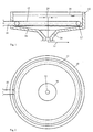
- a round basin 10 In a round basin 10, generally made of concrete, is equidistant from the pool edge one Distributor line 12 arranged, in the immersed state at a distance below the Free-standing mirror 14 near the bottom of the basin 16. As an example distance can be 20 - 40 cm be called in parallel from the pelvic floor.
- At 24 there is a defined outlet. At This point can preferably sit a dip tube. The water then flows over the Outlet 24 from the basin.
- the wastewater passes through the Pool wall in the distribution line 12 a.
- the wastewater to be clarified is then defined fed via the loop 12 to the pool, which, as shown in FIG. 3, at the same distance slotted openings 22 has. These openings can have minimum widths of 5 cm to have.
- the sewage to be clarified flows so close to the water in the Round basin 10 a. It is in the region of the transition from the supply line 18 to Manifold 12 the sewage the maximum flow velocity, at opposite end 12 'have a speed of virtually zero. Distribution line 12 and access line 18 are always full.
- the possibly slit-shaped Inlet openings 22 of the distribution line 12 should be the wastewater to be clarified preferably at an angle of 45 ° in the direction of the pelvic floor.
- the inflow openings on the manifold as slots of At least 5 cm wide, it is possible by changing the slot length, one Adaptation to the hydraulic boundary conditions such as pressure head, pipe friction, etc. to bring about.
- the manifold itself through the drain line 24 with the Drain shaft connected.
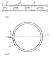
- the measures according to the invention can also Rectangular tanks are applied.
- the ring line is equidistant Following pelvic walls arranged close to the wall and runs parallel to the Beckenwandungen.
- the sludge funnel is designated by 30, the sludge discharge by 32.
- Fig. 4 the flow path in the manifold is shown again schematically. To the division following the supply line 18 are in the two halves tube first high, in the further course to the stagnation point 12 'decreasing speeds. In Point 12 'is the speed equal to zero. The arrow sizes in Fig. 4 indicate the Speed decrease from the beginning of the distribution line 12 to the opposite Point 12 'on.
- the concentric outer inlet pipe an overflow threshold including the gutter as the process.
Claims (11)
- Dispositif pour charger un bassin de décantation de forme circulaire ou rectangulaire avec des eaux usées à épurer, comportant
une conduite d'arrivée (18) et une conduite de distribution (12) de forme annulaire avec orifices de distribution (22) pour les eaux usées à épurer ;
la conduite de distribution (12) de forme annulaire pouvant être disposée dans le bassin de décantation proche de la paroi et proche du fond ; et
les orifices de distribution (22) étant disposés de manière à être orientés dans le bassin de décantation en direction du centre du bassin, suivant une inclinaison d'environ 45° par rapport au fond du bassin, de sorte que pendant le fonctionnement du dispositif il se forme dans le bassin de décantation un courant descendant dirigé vers le centre du bassin. - Dispositif selon la revendication 1, caractérisé en ce que pour réaliser un courant descendant régulier, orienté sur la circonférence depuis le bord du bassin vers le centre, les orifices de distribution (22) présentent des écartements différents sur la conduite de distribution (12).
- Dispositif selon l'une au moins des revendications ou 2, caractérisé en ce que pour réaliser un courant descendant régulier, orienté sur la circonférence depuis le bord du bassin vers le centre, les orifices de distribution (22) sont réalisés en tant que fentes ou perçages avec des longueurs de fente ou des diamètres des trous différents.
- Dispositif selon l'une au moins des revendications 1 à 3, caractérisé en ce que pour réaliser un courant descendant régulier, orienté sur la circonférence depuis le bord du bassin vers le centre, la conduite de distribution (12) comporte des tronçons de diamètres différents.
- Dispositif selon l'une au moins des revendications 1 à 4, caractérisé en ce que les orifices de distribution (22) sont disposés à distance aussi réduite que possible, en particulier de 20 à 40 cm, du fond (16) du bassin.
- Dispositif selon l'une au moins des revendications 1 à 5, caractérisé en ce que la conduite de distribution (12) est disposée équidistante d'un écoulement (24) centré ou concentrique, équidistante d'une extraction centrée des boues et équidistante de la paroi du bassin.
- Dispositif selon l'une au moins des revendications 1 à 6, caractérisé en ce qu'il n'est prévu qu'une seule conduite d'arrivée (18) menant à la conduite de distribution (12).
- Dispositif selon l'une au moins des revendications 1 à 6, caractérisé en ce sont prévues plusieurs conduites d'arrivée (18) menant à la conduite de distribution (12).
- Dispositif selon la revendication 3, caractérisé en ce que les orifices de distribution (22), réalisés en tant que fentes ou perçages, sont adaptés par dimensionnement convenable aux conditions hydrauliques marginales, en particulier à la hauteur de pression ainsi qu'à la pression des tubes et aux pertes locales.
- Dispositif pour traiter des eaux usées comportant un bassin de décantation présentant une forme circulaire ou rectangulaire avec une paroi et un fond de bassin (6) destiné à recevoir des eaux usées à épurer, et comportant un dispositif de chargement du bassin selon l'une des revendications 1 à 9.
- Dispositif selon la revendication 10, caractérisé en ce que pour l'écoulement des eaux usées épurées, il est prévu un tube d'écoulement immergé, disposé au centre, en forme d'étoile.
Applications Claiming Priority (2)
| Application Number | Priority Date | Filing Date | Title |
|---|---|---|---|
| DE19729890 | 1997-07-10 | ||
| DE19729890 | 1997-07-10 |
Publications (2)
| Publication Number | Publication Date |
|---|---|
| EP0890382A1 EP0890382A1 (fr) | 1999-01-13 |
| EP0890382B1 true EP0890382B1 (fr) | 2005-03-23 |
Family
ID=7835487
Family Applications (1)
| Application Number | Title | Priority Date | Filing Date |
|---|---|---|---|
| EP98112559A Expired - Lifetime EP0890382B1 (fr) | 1997-07-10 | 1998-07-07 | Dispositif d'alimentation de bassins circulaires en eau usée à épurer |
Country Status (3)
| Country | Link |
|---|---|
| EP (1) | EP0890382B1 (fr) |
| AT (1) | ATE291476T1 (fr) |
| DE (2) | DE59812671D1 (fr) |
Families Citing this family (1)
| Publication number | Priority date | Publication date | Assignee | Title |
|---|---|---|---|---|
| DE10352038B3 (de) * | 2003-11-07 | 2005-06-09 | Hans Huber Ag Maschinen- Und Anlagenbau | Vorrichtung zur Beschickung von Becken mit zu klärendem Abwasser |
Citations (1)
| Publication number | Priority date | Publication date | Assignee | Title |
|---|---|---|---|---|
| JPS62269719A (ja) * | 1986-05-16 | 1987-11-24 | Chubu Bandou Kk | 沈澱槽における汚泥の沈澱分離方法 |
Family Cites Families (10)
| Publication number | Priority date | Publication date | Assignee | Title |
|---|---|---|---|---|
| US1908102A (en) * | 1927-10-27 | 1933-05-09 | Gustav Staelin | Art of clarifying liquids contaminated by solid matter held in suspension therein and in clarifying apparatus |
| US2185785A (en) * | 1935-06-08 | 1940-01-02 | Dorr Co Inc | Sedimentation process and apparatus |
| US2479126A (en) * | 1945-02-08 | 1949-08-16 | Grace W R & Co | Liquid clarifier |
| US2733986A (en) * | 1949-03-31 | 1956-02-07 | Apparatus fqr crystallizing and separating slightly | |
| GB867948A (en) * | 1958-04-14 | 1961-05-10 | Chain Belt Co | Apparatus for separation of liquids or of solids from a liquid |
| US3534861A (en) * | 1969-10-17 | 1970-10-20 | City Of Detroit The | Settling tanks |
| US4263137A (en) * | 1978-07-19 | 1981-04-21 | Dorr-Oliver Incorporated | Apparatus and method for the gravity settling of suspended solids |
| DE4223863A1 (de) * | 1992-04-09 | 1993-10-14 | Huber Hans Gmbh & Co Kg | Vorrichtung zur Entnahme von geklärtem Abwasser aus Rundbecken |
| US5458777A (en) * | 1994-03-23 | 1995-10-17 | Shell Oil Company | Distributor for liquid separator |
| US5599450A (en) * | 1995-11-20 | 1997-02-04 | Jet Tech, Inc. | Anaerobic upflow batch reactor |
-
1998
- 1998-07-07 DE DE59812671T patent/DE59812671D1/de not_active Expired - Lifetime
- 1998-07-07 DE DE19830311A patent/DE19830311A1/de not_active Withdrawn
- 1998-07-07 EP EP98112559A patent/EP0890382B1/fr not_active Expired - Lifetime
- 1998-07-07 AT AT98112559T patent/ATE291476T1/de not_active IP Right Cessation
Patent Citations (1)
| Publication number | Priority date | Publication date | Assignee | Title |
|---|---|---|---|---|
| JPS62269719A (ja) * | 1986-05-16 | 1987-11-24 | Chubu Bandou Kk | 沈澱槽における汚泥の沈澱分離方法 |
Also Published As
| Publication number | Publication date |
|---|---|
| ATE291476T1 (de) | 2005-04-15 |
| EP0890382A1 (fr) | 1999-01-13 |
| DE19830311A1 (de) | 1999-01-14 |
| DE59812671D1 (de) | 2005-04-28 |
Similar Documents
| Publication | Publication Date | Title |
|---|---|---|
| EP0596052B1 (fr) | Procede et dispositif d'entree pour l'alimentation de dessableurs plats ou de bassins de decantation/bassin de decantation finale | |
| EP2201992A1 (fr) | Procédé et dispositif destinés à épaissir de la boue charriée par les eaux usées | |
| DE2401550A1 (de) | Vorrichtung zur schlammbeseitigung | |
| DE2845185A1 (de) | Verfahren und vorrichtung zum ausscheiden von feststoffen aus fluessigkeiten | |
| EP1090664B1 (fr) | Evacuation des boues flottantes | |
| EP0890382B1 (fr) | Dispositif d'alimentation de bassins circulaires en eau usée à épurer | |
| DE3821521C2 (de) | Klärbecken | |
| EP0668242B1 (fr) | Dispositif pour le prélèvement régulièrement distribué des eaux usées clarifiées dans la périphérie d'un bassin circulaire de sédimentation | |
| EP1148951B1 (fr) | Dispositif de separation tangentielle de matieres solides | |
| DE2527978C2 (de) | Regenrückhaltebecken | |
| DE4431369C2 (de) | Vorrichtung für die Klärung von Abwasser | |
| EP1023117B1 (fr) | Installation de refoulement de boues en nappe pour traiter de l'eau potable | |
| EP0621076A1 (fr) | Procédé pour la séparation de solides | |
| CH650230A5 (en) | Device for separating solids from liquids | |
| DE4235438C2 (de) | Ablaufsystem für Absetzbecken | |
| DE1708604B2 (de) | Anlage zur biologischen reinigung von abwasser | |
| DE3904103C2 (de) | Verteilervorrichtung zur gleichmäßigen Verteilung von Abwasser | |
| DE1459454C (de) | Vorrichtung zum Abscheiden von Schlamm aus Abwässern biologischer Kläranlagen | |
| DE2120542C3 (de) | Vorrichtung zur biologischen Reinigung von Abwasser nach dem Belebtschlammverfahren | |
| EP3610936A1 (fr) | Bassin de sédimentation et procédé de guidage de courants partiels dans une zone d'admission du bassin de sédimentation | |
| EP0022423A2 (fr) | Dispositif pour le traitement de l'eau brute, telle que l'eau de surface, l'eau d'égout, ou une eau similaire par sédimentation | |
| WO1983000097A1 (fr) | Procede et dispositif de traitement d'un liquide | |
| AT411249B (de) | Klär- oder absetzbecken | |
| DE1584956C (fr) | ||
| EP0890383A1 (fr) | Dispositif de prelèvement d'eau usée clarifiée de bassins circulaires |
Legal Events
| Date | Code | Title | Description |
|---|---|---|---|
| PUAI | Public reference made under article 153(3) epc to a published international application that has entered the european phase |
Free format text: ORIGINAL CODE: 0009012 |
|
| AK | Designated contracting states |
Kind code of ref document: A1 Designated state(s): AT CH DE LI |
|
| AX | Request for extension of the european patent |
Free format text: AL;LT;LV;MK;RO;SI |
|
| 17P | Request for examination filed |
Effective date: 19990630 |
|
| AKX | Designation fees paid |
Free format text: AT CH DE LI |
|
| 17Q | First examination report despatched |
Effective date: 20020730 |
|
| GRAH | Despatch of communication of intention to grant a patent |
Free format text: ORIGINAL CODE: EPIDOS IGRA |
|
| GRAS | Grant fee paid |
Free format text: ORIGINAL CODE: EPIDOSNIGR3 |
|
| GRAA | (expected) grant |
Free format text: ORIGINAL CODE: 0009210 |
|
| AK | Designated contracting states |
Kind code of ref document: B1 Designated state(s): AT CH DE LI |
|
| REG | Reference to a national code |
Ref country code: CH Ref legal event code: NV Representative=s name: RIEDERER HASLER & PARTNER PATENTANWAELTE AG Ref country code: CH Ref legal event code: EP |
|
| REF | Corresponds to: |
Ref document number: 59812671 Country of ref document: DE Date of ref document: 20050428 Kind code of ref document: P |
|
| PGFP | Annual fee paid to national office [announced via postgrant information from national office to epo] |
Ref country code: AT Payment date: 20050628 Year of fee payment: 8 |
|
| PGFP | Annual fee paid to national office [announced via postgrant information from national office to epo] |
Ref country code: CH Payment date: 20050722 Year of fee payment: 8 |
|
| PLBE | No opposition filed within time limit |
Free format text: ORIGINAL CODE: 0009261 |
|
| STAA | Information on the status of an ep patent application or granted ep patent |
Free format text: STATUS: NO OPPOSITION FILED WITHIN TIME LIMIT |
|
| 26N | No opposition filed |
Effective date: 20051227 |
|
| PG25 | Lapsed in a contracting state [announced via postgrant information from national office to epo] |
Ref country code: AT Free format text: LAPSE BECAUSE OF NON-PAYMENT OF DUE FEES Effective date: 20060707 |
|
| PG25 | Lapsed in a contracting state [announced via postgrant information from national office to epo] |
Ref country code: LI Free format text: LAPSE BECAUSE OF NON-PAYMENT OF DUE FEES Effective date: 20060731 Ref country code: CH Free format text: LAPSE BECAUSE OF NON-PAYMENT OF DUE FEES Effective date: 20060731 |
|
| REG | Reference to a national code |
Ref country code: CH Ref legal event code: PL |
|
| PGFP | Annual fee paid to national office [announced via postgrant information from national office to epo] |
Ref country code: DE Payment date: 20120726 Year of fee payment: 15 |
|
| REG | Reference to a national code |
Ref country code: DE Ref legal event code: R119 Ref document number: 59812671 Country of ref document: DE Effective date: 20140201 |
|
| PG25 | Lapsed in a contracting state [announced via postgrant information from national office to epo] |
Ref country code: DE Free format text: LAPSE BECAUSE OF NON-PAYMENT OF DUE FEES Effective date: 20140201 |