EP0890329B1 - Rayonnage avec dispositif de déchargement - Google Patents
Rayonnage avec dispositif de déchargement Download PDFInfo
- Publication number
- EP0890329B1 EP0890329B1 EP98110261A EP98110261A EP0890329B1 EP 0890329 B1 EP0890329 B1 EP 0890329B1 EP 98110261 A EP98110261 A EP 98110261A EP 98110261 A EP98110261 A EP 98110261A EP 0890329 B1 EP0890329 B1 EP 0890329B1
- Authority
- EP
- European Patent Office
- Prior art keywords
- recited
- storage shelves
- ejection
- channels
- ejector
- Prior art date
- Legal status (The legal status is an assumption and is not a legal conclusion. Google has not performed a legal analysis and makes no representation as to the accuracy of the status listed.)
- Expired - Lifetime
Links
Images


Classifications
-
- B—PERFORMING OPERATIONS; TRANSPORTING
- B65—CONVEYING; PACKING; STORING; HANDLING THIN OR FILAMENTARY MATERIAL
- B65G—TRANSPORT OR STORAGE DEVICES, e.g. CONVEYORS FOR LOADING OR TIPPING, SHOP CONVEYOR SYSTEMS OR PNEUMATIC TUBE CONVEYORS
- B65G1/00—Storing articles, individually or in orderly arrangement, in warehouses or magazines
- B65G1/02—Storage devices
- B65G1/04—Storage devices mechanical
- B65G1/06—Storage devices mechanical with means for presenting articles for removal at predetermined position or level
- B65G1/08—Storage devices mechanical with means for presenting articles for removal at predetermined position or level the articles being fed by gravity
-
- A—HUMAN NECESSITIES
- A47—FURNITURE; DOMESTIC ARTICLES OR APPLIANCES; COFFEE MILLS; SPICE MILLS; SUCTION CLEANERS IN GENERAL
- A47F—SPECIAL FURNITURE, FITTINGS, OR ACCESSORIES FOR SHOPS, STOREHOUSES, BARS, RESTAURANTS OR THE LIKE; PAYING COUNTERS
- A47F1/00—Racks for dispensing merchandise; Containers for dispensing merchandise
- A47F1/04—Racks or containers with arrangements for dispensing articles, e.g. by means of gravity or springs
- A47F1/12—Racks or containers with arrangements for dispensing articles, e.g. by means of gravity or springs dispensing from the side of an approximately horizontal stack
-
- B—PERFORMING OPERATIONS; TRANSPORTING
- B65—CONVEYING; PACKING; STORING; HANDLING THIN OR FILAMENTARY MATERIAL
- B65G—TRANSPORT OR STORAGE DEVICES, e.g. CONVEYORS FOR LOADING OR TIPPING, SHOP CONVEYOR SYSTEMS OR PNEUMATIC TUBE CONVEYORS
- B65G1/00—Storing articles, individually or in orderly arrangement, in warehouses or magazines
- B65G1/02—Storage devices
- B65G1/04—Storage devices mechanical
- B65G1/137—Storage devices mechanical with arrangements or automatic control means for selecting which articles are to be removed
- B65G1/1373—Storage devices mechanical with arrangements or automatic control means for selecting which articles are to be removed for fulfilling orders in warehouses
Definitions
- the invention relates to a shelf, in particular for small-sized goods such as medicines for pharmacies (see publication DE-A-43 36 885).
- small-sized goods such as medicines for pharmacies
- pharmacies see publication DE-A-43 36 885.
- the problem of the multitude of sales goods arises especially in pharmacies. Thousands of medicines are kept. This requires well-organized warehousing.
- the shelves in pharmacies are designed accordingly.
- each medicinal product will occupy a certain place on the shelves. Warehousing also entails considerable responsibility, because emergencies must be taken into account with the availability of the medication.
- a similar problem can also arise with other, even larger goods.
- Such storage goods can include shoe boxes
- Shelving systems have been available for years to make it easier to find medicines. This shortens the time required.
- the shelves are also offered with automatic unloading devices and with automatic filling equipment.
- the automatic unloading device and filling device have so far not been able to establish themselves correctly.
- the lack of enforcement is attributed to difficulties in the unloading and filling devices. Overall, the devices are too expensive and too complicated. Every construction part is a source of error.
- the object of the invention is therefore to create a simple and reliable construction. This object is solved by the features of claim 1.
- the invention is based on the fact that the used in all facilities Gripping mechanism forms a very special source of interference.
- the gripping mechanism is extremely complex and requires maintenance. Its control must be extremely precise.
- the unloading device is significantly simplified in that instead of Gripping mechanism a plunger (ejection lever) is provided.
- a plunger ejection lever
- the plunger lifts the products / items out of the associated shaft and preferably has the Pusher an incline so that the products / items on the pestle are out of the area of the Slip down and catch and can be fed to their destination.
- the products / articles are undercut for lifting. In the shaft you will find the Underneath the products / articles a recess.
- T-shaped rails, the vertical web of which points upwards, are particularly suitable the products / articles rest on their horizontal lateral webs.
- the T-shaped Rails are spaced from each other so that the plunger for lifting the Can grab products / items between the rails. By simultaneous inclination of the Rails on the removal side cause the products / articles to slide into the due to their weight correct removal position.
- the container Used to catch the excavated products that slide off the pestle a collecting device in the form of a container.
- the container can be open in shape Have box. By tilting the container and opening the back wall, the glide Products / articles from the inclined container onto a conveyor belt or another Conveyor.
- the tappet according to the invention is along the shelf like known unloading devices movable and also provided with a lifting and lowering device.
- the lifting and lowering drive also forms the drive for lifting the ram. To underline the The ram is moved up to products / articles. However, the movement of the plunger requires Comparatively little effort compared to the known device.
- the drive can be of any type. Suitable drives are electrical or hydraulic or pneumatic drives. Likewise, purely mechanical drives are used of the ram, also linear drives. The drive can at the same time Form ram guide. Optionally, a separate plunger guide is also provided.
- the tappet according to the invention is advantageously omitted known devices also the gripper drive including control.
- a novel chassis for the plunger and the Lifting device provided.
- the unloading device is operated hanging.
- the hanging Arrangement has the advantage of great ground clearance.
- the hanging arrangement has also for other sampling devices advantages.
- a track arranged in the upper area of the shelves is used for hanging arrangement.
- the running track takes the total weight of the device and the vertical loads from operation.
- the profile of the running rail is selected accordingly.
- a carriage runs on the horizontal track, which can be moved with a toothed belt and carries another vertically arranged track.
- the vertically arranged running rail is prevented by stiffening the carriage frame from undesired movement in the plane in which the two running rails lie.
- a guide rail at the foot of the vertical guide rail prevents undesired movement transversely to the plane mentioned.
- the vertical guide rail can be designed in the same way as the horizontal guide rail and can be provided with a toothed belt drive.
- the core of the guide rails are precision profiles, e.g. made of aluminium.
- At both Rail ends have deflections for the belt drive.
- Optional is at one end at the same time a pulley with a drive motor is provided.
- the ends of the Timing belts are attached to the crawler so that the crawler over the engine the timing belt can be moved.
- the trolley is optionally equipped with two-row profile rollers, the wave sound path is designed as a Gothic arch.
- the trolleys can be used with a any number of profile rollers can be equipped.
- the profile rollers are with Steel strips attached directly to a carriage plate. The construction is very rigid The guides are adjusted without play using eccentric bushes.
- the unloading device according to the invention is preferably combined with a novel control system. This is achieved with the help of a frame that consists of side walls and trusses on which T-shaped rails are held, the T-shaped rails pointing downwards with the vertical web and the products / articles laterally with the two horizontal lateral webs under attack.
- the use of the T-shaped rails alone results in a considerable reduction in construction costs because it is unnecessary to support the products / articles over their entire area.
- the packaging is all so stable or can be designed so that the products / articles do not fall through fear. This is also an advantage if a shelf is created without the change in distance according to the invention. Due to the possible distance change, the pharmacist can convert his shelf at any time and adapt it to his business.
- the T-shaped rails are preferably screwed or pinned to the cross members and the associated holes are arranged in a grid dimension.
- the grid dimension facilitates the correct assembly because only the holes have to be counted and no distance has to be measured in order to arrange the rails exactly parallel to one another and to the side walls of the shelves.
- the grid size also has the advantage that the position of the respective shafts can be counted using the holes. This facilitates the control of an unloading device and / or filling device.
- the grid dimension is optionally up to 20 mm. The smaller the grid size, the more precisely the adaptation to the products / articles is possible.
- the grid dimension is preferably less than 10 mm. Favorable conditions result with a grid dimension of 5 mm or 5.04 mm
- the holes can be holes with a diameter that is chosen to be small.
- Grid dimensions of 5 mm can give diameters from 1 mm to 3 mm favorable conditions. The smallest diameter is not necessarily the cheapest, because e.g. at a With a diameter of one millimeter, the drill bits break easily and threaded screws easily be overwrought. Bores with 3 mm, including threaded bores, are particularly good Make M 3. Users have more experience in handling M 3 screws than with smaller screws. In the use of such screws there is still sufficient There is material between the screw holes when the pitch is 5 or 5.04 mm is.
- the screws can be seen from above through lateral and horizontal webs of the T-shaped Rails are inserted into the trusses. But it is also possible to use the T-shaped Screw the rails on the head side.
- the T-shaped rails for this purpose underlaid on the head side with a piece of material that has at least one through hole for the Has screw connection with the trusses. The piece of material is alternatively with the Screwed T-shaped rail.
- the trusses can consist of solid material. Profiles can also be used. The same applies to the side cheeks. Frame constructions for the side walls, which consist of square profiles with a square cross-section and are provided with longitudinal grooves in the middle on at least two sides, are favorable; profiles with a central groove on each side surface are better. Such profiles are offered in an aluminum that is easy to handle and process. It is advisable to manufacture as many parts of the bearing as possible from the same profiles. This includes the unloader.
- the T-shaped profile is also composed of two L-shaped profiles
- the maximum module width in pharmacies is preferably 2 m.
- the direction of travel of the unloading devices and filling devices is the same as the module width Travel length along the module
- the unloading device according to the invention and / or the rack are optionally combined with a filling device which fills the rack on the side facing away from the unloading device.
- a filling device which fills the rack on the side facing away from the unloading device.
- the incline of the shaft helps here because the stored goods slide down to the removal side due to their weight.
- a device similar to the collecting container of the unloading device is proposed. Ie there is an inclined container with a flap at the lower end. By folding down the flap, the gap can be bridged up to the intended shaft and the cargo can be directed onto the shelf. It is favorable if the flap which is folded down continues the inclination of the container in whole or in part.
- the inclined container serving as the filling device can be provided with a holding lever instead of the flap.
- the holding lever can be moved, for example, by means of a lifting magnet, or also by means of a stepping motor with a gear or other type. Linear guidance is also possible, in which the lifting magnet can act directly on the stored goods. It is advantageous if the lever at the front is as flat as possible so that the filling device can be moved as close as possible behind the shelf. This reduces the gap to be bridged. Lateral guidance of the cargo is also beneficial.
- the lateral guide can consist of a retaining pin or a retaining wall. It is useful if the pin and / or wall are moved to a dimension that is slightly larger than the package width.
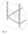
- the developed picking system for small parts, especially pharmacy products consists of at least one bearing module 1, the basic structure of which consists of standard aluminum construction profiles built up and on the floor and preferably also on the Ceiling is attached.
- the threaded strips are commercially available (19 '' accessories) and have threads arranged in the longitudinal direction in a 5.04 mm grid.
- Each of the guide channels 29 (sloping towards the front) for the product-specific reception of product packs 24 consists of one or two T or L profiles 27, each of which is attached to the cross struts 22, 23 by means of screws 25 and the already mentioned fastening quadrilateral (26) be attached.
- the L- (angle) profiles 27 are also preferably used for non-angular (ie round, oval, rounded etc.) packs.
- Screws 25 are preferably used as fastening screws for the guide profiles have a large head (preferably Allen screws), because they are in addition to the Fixing especially the fixation of the product packs in the guide channel serve (Fig. 2).
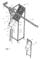
- a ceiling-guided standard robot linear unit is located in front of the storage modules in the horizontal direction 3, on the carriage 4 with a further standard linear unit 5 vertical orientation is attached. Both linear units are over toothed belt 6 (in the the drawing only indicated) driven by electric motors 7.
- the roller 8 for receiving the torque should preferably be used be omitted. According to the current state of trials with the real plant leads this does not lead to intolerable vibrations.
- an arrangement of two wheels is provided in another exemplary embodiment.
- the wheels are mounted so that they are pressed onto the ground by spring pressure.
- the adjustable pressure is so low that jamming of the vertical axis is prevented, but just enough to dampen the axis vibrations that occur.
- the vibration damping is further enhanced by installing and also driving a second horizontal axis in order to give the vertical axis further stability and to ensure a higher travel speed.
- An arrangement of the parallel axis below the upper horizontal axis or laterally offset, if necessary also tilted by 90 degrees, can be considered.
- the removal device 9 consists of a flat, slightly round and towards the front tapered push lever 10 (this push lever can of course have any other shape, as long as it only serves its purpose), which can be achieved using a suitable linear drive (currently a Rack and pinion, but other options are of course also conceivable) can be extended.
- This push lever is located over a suitably shaped one Sheet metal (or plastic molding) 11, via which the ejected product pack in the collecting container 13 slides under the plunger. Packs that are not fast enough automatically fall laterally towards the top opening of the collecting container a second sheet (or plastic molding) 12 deflected in the correct direction.
- the ejection lever can (but does not have to) be equipped with a pressure or touch sensor system at its tip, which can stop the lever from extending if the positioning has not been carried out correctly for any reason.
- the system could then try to vary the position slightly in all four directions in order to guarantee removal as possible and, if successful, to replace the originally stored position with the newly found position in a kind of self-learning process.
- this procedure would protect the system itself from damage and self-destruction, and on the other hand, if the guide channel arrangement was measured manually, it would allow greater fault tolerance, which would mean considerable time savings due to faster (because less precise) measurements for several thousand channels.
- a similar effect could also be achieved by software-based time measurement.
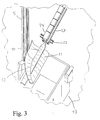
- the collecting container 13 has by inclined container arrangement or by inclined Floor arrangement with vertical walls an inclined floor, which from the Guides ejected packs slide up to the front dispensing opening, which is closed by a flap 14 similar to a sliding door.
- This flap can by means of the attached hook 15 and the corresponding eyelet 17 at the delivery points 16 by appropriate movement of the horizontal and vertical axes of the system without own drive mechanism can be opened and closed. This will reduce costs and (never 100% trouble-free) mechanical-electrical components and associated Cabling saved.
- the eyelet for opening the flap is simple Metal bracket replaced by a magnetic snap attached to the container flap be approached, and so opening and closing the flap by moving the Allow container. This process is less complex and more reliable and quieter in operation, the risk of destruction due to adjusted eyelets is eliminated.
- the product packs are transported on to the sales table by generally known and distributed transport systems, but preferably by linear units similar to those for the main axes (because of the high acceleration and speed values that can be achieved) and / or by slipping (because of the low costs and the elimination of technology and maintenance). ,
- the ejection and collecting device is furthermore optionally available with a sensor system 19 equipped, the set the optical, inductive or capacitive ways Can determine positions of the guide channels. This happens because the device is moved in a grid pattern along the installed storage modules and every time the Front side of a guide profile 27 or the associated fastening cuboid 26 recognized is sent a signal to the computer control which causes it to change the current position of the save two main axes so that you can e.g. to be able to access position data stored on the hard disk.
- end face barcodes which are either the type of stored Product, the type of management profile used, other information or simply one Code the channel number.
- a barcode reader 20 is also attached in addition to the position sensor system. This addition is also optional and will be used in commercial evaluation Performance and price expectations of the customer installed accordingly or omitted.
- the system In the event of a malfunction that can never be ruled out, the system must be equipped with a device that enables the operator to find products again (in the warehouse, not sorted alphabetically, but according to removal frequency and pack sizes).
- alphanumeric displays in the form of commercially available LED or LCD modules or conventional computer screens or LCD flat screens 21 are preferably attached to at least one storage module. Any possible attachment to another location must of course be provided so that a person standing in front of the storage module (s) can easily read the information displayed.
- the described incident report informs the person (s) responsible for picking which products are to be collected for which delivery point (in the sales room) or for which order and in what quantity and in which storage module they are housed.
- Finding the module and the correct guide channel is made possible by a grid, formed by index elements 31, facilitated by the computer of the system in such a way can be controlled that for each pack a rectangular field 30 of the storage module in the respective delivery point (in the sales room) or in a product group (complete Order) is marked.
- Each operator is assigned a color based on which he can recognize which indicator light is intended for him.
- each index element has several Equipped LEDs that are either different colors or in any case different colors to shine. This means that several operators can work simultaneously, depending on the number of colors available and are supported independently of each other in manual picking. It is the same It is possible to display several storage locations (different products) to each operator at the same time.
- the index of the storage location is therefore not only displayed alphanumerically, but at the same time marked directly.
- faster location even if the building lighting fails in the event of a power failure. In some European regions, every thunderstorm brings one up to several hours of power failure.
- the product chute is found by a Lamp that lights up on the corresponding module, as well as by the alphanumeric Level and shaft display. This applies to both manual loading of the shelf as well as in the event that the robot fails due to a malfunction. The originally intended indexing is no longer applicable.
- the computer of course, has an uninterruptible power supply Power outages protected. This also supplies the entire information and Signaling system.
- the hook can be designed to be folded away, Similar to the protective mechanism known from car exterior mirrors, but with the Execution of the system described here the folding mechanism self-resetting design (in contrast to the car mirror).
Claims (20)
- Rayonnage pour marchandises minuscules, particulièrement destiné aux pharmacies, où plusieurs canaux inclinés (29) sont rangés de façon superposée et côte à côte, avec un dispositif d'éjection (9) étant commun pour un grand nombre de canaux, lequel peut être déplacé horizontalement et verticalement devant les canaux,
caractérise du fait que le dispositif d'éjection, comme dispositif d'éjection et de recueil (9), est formé par un poussoir éjecteur (10) pouvant être avancer et reculer et un réceptacle collecteur (13), où le dispositif d'éjection et de recueil (9) est formé de manière que pour la prise d'une marchandise (24) le dispositif d'éjection et de recueil (9) est positionné devant le canal correspondant, le poussoir d'éjection est avancé et puis l'entier dispositif d'éjection et de recueil (9) est lever verticalement, par où la marchandise la plus en avant est éjectée par le poussoir d'éjection et glisse dans le réceptacle collecteur (13). - Rayonnage selon la revendication 1, caractérisé par une disposition de poussoir éjecteur inclinée et/ou une glissière (12) faisant partie du poussoir éjecteur (10).
- Rayonnage selon la revendication 1 ou 2, caractérisé du fait qu'il est prévu un guidage du poussoir à côté de l'entraínement du poussoir ou un entraínement du poussoir formant un guidage lui-même.
- Rayonnage selon une des revendications 1 à 3, caractérisé par une disposition suspendue du dispositif de prise de marchandises.
- Rayonnage selon une des revendications 1 à 4, caractérisé par un rail de roulement horizontal (3) avec une courroie crantée et/ou rail de roulement vertical (5) avec une courroie crantée.
- Rayonnage selon la revendication 4 ou 5, caractérisé par un guidage coulissant (4) sur le rail horizontal (3) et portant le rail vertical (5).
- Rayonnage selon la revendication 5 ou 6, caractérisé par un rail de guidage bas.
- Rayonnage selon une des revendications 1 à 7, caractérisé par le couplage du poussoir éjecteur avec un bloc détecteur.
- Rayonnage selon la revendication 8, caractérisé par un bloc détecteur de pression/force et/ou un bloc détecteur de contact et/ou un bloc détecteur optique et/ou un bloc détecteur d'induction et/ou un bloc détecteur de capacité.
- Rayonnage selon une des revendications 1 à 9, caractérisé par une commande de traitement de l'information avec chronomètre et/ou compteur de canaux et/ou compteur de niveau et/ou lecteur de code-à-barres et des codes-à-barres aux canaux et/ou aux marchandises.
- Rayonnage selon une des revendications 1 à 10, caractérisé par une commande de traitement de l'information avec fonction de contrôle autodictactique et/ou compensation d'erreurs.
- Rayonnage selon une des revendications 1 à 11, caractérisé par un affichage alphanumérique.
- Rayonnage selon une des revendications 1 à 12, caractérisé par des canaux formés par des surfaces de repos et des séparations y étant perpendiculaires, où les distances entre les séparations (27) sont ajustables.
- Rayonnage selon la revendication 13, caractérisé du fait que les séparations (27) sont tenues par des rails en T ou en L.
- Rayonnage selon la revendication 13 ou 14, caractérisé par une dimension de trame de l'ajustage des séparations (27) inférieure à 10 mm.
- Rayonnage selon une des revendications 13 à 15, caractérisé par un vissage des rails (27) aux traverses par le haut ou un vissage sur la face, où des cales (26) - avec au moins un trou de passage pour le boulonnage - sont placées en dessous des rails (27).
- Rayonnage selon une des revendications 1 à 16, caractérisé par des profils 4 pans (5) en aluminium ayant des rainures à leurs faces latérales munis de bandes filetées (23).
- Rayonnage selon une des revendications 1 à 17, caractérisé par un réceptacle collecteur avec un fond incliné et une trappe ou un levier de retenu.
- Rayonnage selon la revendication 18, caractérisé du fait que la trappe superpose la fente au canal destiné.
- Rayonnage selon une des revendications 13 à 19, caractérisé par un guidage latéral des marchandises/articles au passage vers les canaux et/ou depuis les canaux.
Applications Claiming Priority (2)
| Application Number | Priority Date | Filing Date | Title |
|---|---|---|---|
| DE19724378 | 1997-06-11 | ||
| DE19724378A DE19724378C2 (de) | 1997-06-11 | 1997-06-11 | Stapelregal mit Entladevorrichtung |
Publications (2)
| Publication Number | Publication Date |
|---|---|
| EP0890329A1 EP0890329A1 (fr) | 1999-01-13 |
| EP0890329B1 true EP0890329B1 (fr) | 2004-03-24 |
Family
ID=7832004
Family Applications (1)
| Application Number | Title | Priority Date | Filing Date |
|---|---|---|---|
| EP98110261A Expired - Lifetime EP0890329B1 (fr) | 1997-06-11 | 1998-06-05 | Rayonnage avec dispositif de déchargement |
Country Status (3)
| Country | Link |
|---|---|
| EP (1) | EP0890329B1 (fr) |
| AT (1) | ATE262297T1 (fr) |
| DE (2) | DE19724378C2 (fr) |
Families Citing this family (7)
| Publication number | Priority date | Publication date | Assignee | Title |
|---|---|---|---|---|
| DE10355471B4 (de) * | 2003-11-27 | 2007-02-01 | Daimlerchrysler Ag | Regal- und Fördervorrichtung |
| DE102005012516A1 (de) * | 2005-03-16 | 2006-09-21 | Dirk Rolf Beils | Verfahren und Lagersystem für die rechnergestützte Lagerung von Arzneimitteln |
| BR112013002956A2 (pt) * | 2010-08-12 | 2016-06-07 | Automatismos Y Montajes Ind J Martin S L | instalação automática para armazenar e distribuir produtos |
| CN102001505B (zh) * | 2010-10-21 | 2012-11-28 | 山东兰剑物流科技股份有限公司 | 一种盒装物品自动分拣机 |
| FR2997321B1 (fr) * | 2012-10-29 | 2014-12-05 | Pharmacie Automatisme | Installation de stockage et de delivrance de boites de medicaments |
| DE102021205334A1 (de) | 2021-05-26 | 2022-12-01 | Robert Bosch Gesellschaft mit beschränkter Haftung | Linearmodul und Verfahren zum Betrieb eines Linearmoduls |
| CN116439548A (zh) * | 2023-04-19 | 2023-07-18 | 安徽统汇道具设计制作有限公司 | 一种多角度展示的斜面陈列架 |
Family Cites Families (9)
| Publication number | Priority date | Publication date | Assignee | Title |
|---|---|---|---|---|
| US3674159A (en) * | 1969-03-07 | 1972-07-04 | Triax Co | Load handling mechanism and automatic storage system |
| US4307988A (en) * | 1971-12-28 | 1981-12-29 | Page Peter H | Storage system |
| GB2136411A (en) * | 1983-01-20 | 1984-09-19 | Acrow Storage Equipment Limite | Racking with forward-feed |
| JPH0237080Y2 (fr) * | 1985-09-12 | 1990-10-08 | ||
| FR2678540B1 (fr) * | 1991-07-05 | 1997-01-17 | Eric Courtin | Procede et systeme d'aide a la distribution et au choix de pieces pour l'assemblage d'objets sur une chaine de montage industrielle. |
| US5337919A (en) * | 1993-02-11 | 1994-08-16 | Dispensing Technologies, Inc. | Automatic dispensing system for prescriptions and the like |
| DE9315118U1 (de) * | 1993-10-06 | 1993-12-16 | Staude Gmbh M | Komissionierungsanlage für Apothekenprodukte |
| DE29502314U1 (de) * | 1995-02-14 | 1995-04-06 | Kramer Clemens | Regalsystem |
| JPH09223269A (ja) * | 1995-12-14 | 1997-08-26 | Silk Hosei Kojo:Kk | 自動販売装置 |
-
1997
- 1997-06-11 DE DE19724378A patent/DE19724378C2/de not_active Expired - Fee Related
-
1998
- 1998-06-05 EP EP98110261A patent/EP0890329B1/fr not_active Expired - Lifetime
- 1998-06-05 AT AT98110261T patent/ATE262297T1/de not_active IP Right Cessation
- 1998-06-05 DE DE59811038T patent/DE59811038D1/de not_active Expired - Fee Related
Also Published As
| Publication number | Publication date |
|---|---|
| EP0890329A1 (fr) | 1999-01-13 |
| ATE262297T1 (de) | 2004-04-15 |
| DE59811038D1 (de) | 2004-04-29 |
| DE19724378A1 (de) | 1998-12-24 |
| DE19724378C2 (de) | 2000-10-12 |
Similar Documents
| Publication | Publication Date | Title |
|---|---|---|
| EP1820754B1 (fr) | Système d'étagère et procédé de stockage automatisé de petits objets | |
| EP1136394B1 (fr) | Dispositif pour la composition de commandes | |
| DE4336885A1 (de) | Kommissionierungsanlage für Apothekenprodukte | |
| EP1140670A2 (fr) | Procede et systeme d'entreposage destines au transfert de charges | |
| EP0678461A1 (fr) | Rayonnage d'emmagasinage surélevé | |
| DE102013013021A1 (de) | Speicherteil mit Platte, Gehäuseteil und Bolzenabschnitt, insbesondere Bolzen, und Lagersystem mit einem Kettentrieb | |
| EP1423314B1 (fr) | Magasin a rayonnage comportant des tiroirs montes dans les compartiments de rayonnage | |
| DE2807002A1 (de) | Paletten-regallager | |
| WO2014072265A1 (fr) | Extracteur de marchandise stockée pour un système de stockage automatique | |
| EP0890329B1 (fr) | Rayonnage avec dispositif de déchargement | |
| EP1218265B1 (fr) | Entrepot a rayonnages | |
| EP0098573A1 (fr) | Dispositif d'alimentation de pièces | |
| EP0286986A1 (fr) | Dispositif d'emmagasinage | |
| DE19724377C2 (de) | Regal mit Schachtsystem | |
| DE19635396A1 (de) | Regallagersystem mit einem Regalbediengerät für die Handhabung von Stückgut | |
| WO2001070602A2 (fr) | Dispositif de preparation de commandes comportant des compartiments de stockage disposes dans un rayon et une unite d'ejection positionnable | |
| EP1910194A1 (fr) | Systeme de stockage a rayonnages comprenant une station d'entree | |
| EP1744974A1 (fr) | Support a rayonnages presentant des separateurs amovibles sur le fond des rayonnages | |
| DE10004232A1 (de) | Antriebseinrichtung für eine Lagervorrichtung | |
| EP0416627B1 (fr) | Procédé et dispositif pour stocker et reprendre automatiquement des sortes de marchandises de détail de rayonnages dans de grands entrepôts | |
| EP0991036A2 (fr) | Distributeur avec un manipulateur de distribution commun | |
| EP1445215B1 (fr) | Dispositif et procédé de stockage d'articles | |
| DE10227988A1 (de) | Verfahren und Regalbediengerät zum Bedienen eines Regals vorzugsweise in einer Kommissionieranlage | |
| DE4442696A1 (de) | Halbautomatische fahrbare Regalspeichervorrichtung | |
| EP3360825A1 (fr) | Dispositif de commande d'étagère pourvu de parties de fond mobiles et procédé de retrait d'une unité marchandises d'une étagère à marchandises |
Legal Events
| Date | Code | Title | Description |
|---|---|---|---|
| PUAI | Public reference made under article 153(3) epc to a published international application that has entered the european phase |
Free format text: ORIGINAL CODE: 0009012 |
|
| AK | Designated contracting states |
Kind code of ref document: A1 Designated state(s): AT BE CH DE DK ES FI FR GB GR IE IT LI LU MC NL PT SE |
|
| AX | Request for extension of the european patent |
Free format text: AL;LT;LV;MK;RO;SI |
|
| 17P | Request for examination filed |
Effective date: 19981221 |
|
| AKX | Designation fees paid |
Free format text: AT BE CH DE DK ES FI FR GB GR IE IT LI LU MC NL PT SE |
|
| 17Q | First examination report despatched |
Effective date: 20020514 |
|
| GRAH | Despatch of communication of intention to grant a patent |
Free format text: ORIGINAL CODE: EPIDOS IGRA |
|
| GRAS | Grant fee paid |
Free format text: ORIGINAL CODE: EPIDOSNIGR3 |
|
| GRAA | (expected) grant |
Free format text: ORIGINAL CODE: 0009210 |
|
| AK | Designated contracting states |
Kind code of ref document: B1 Designated state(s): AT BE CH DE DK ES FI FR GB GR IE IT LI LU MC NL PT SE |
|
| PG25 | Lapsed in a contracting state [announced via postgrant information from national office to epo] |
Ref country code: NL Free format text: LAPSE BECAUSE OF FAILURE TO SUBMIT A TRANSLATION OF THE DESCRIPTION OR TO PAY THE FEE WITHIN THE PRESCRIBED TIME-LIMIT Effective date: 20040324 Ref country code: IT Free format text: LAPSE BECAUSE OF FAILURE TO SUBMIT A TRANSLATION OF THE DESCRIPTION OR TO PAY THE FEE WITHIN THE PRESCRIBED TIME-LIMIT;WARNING: LAPSES OF ITALIAN PATENTS WITH EFFECTIVE DATE BEFORE 2007 MAY HAVE OCCURRED AT ANY TIME BEFORE 2007. THE CORRECT EFFECTIVE DATE MAY BE DIFFERENT FROM THE ONE RECORDED. Effective date: 20040324 Ref country code: IE Free format text: LAPSE BECAUSE OF FAILURE TO SUBMIT A TRANSLATION OF THE DESCRIPTION OR TO PAY THE FEE WITHIN THE PRESCRIBED TIME-LIMIT Effective date: 20040324 Ref country code: GB Free format text: LAPSE BECAUSE OF FAILURE TO SUBMIT A TRANSLATION OF THE DESCRIPTION OR TO PAY THE FEE WITHIN THE PRESCRIBED TIME-LIMIT Effective date: 20040324 Ref country code: FR Free format text: LAPSE BECAUSE OF FAILURE TO SUBMIT A TRANSLATION OF THE DESCRIPTION OR TO PAY THE FEE WITHIN THE PRESCRIBED TIME-LIMIT Effective date: 20040324 Ref country code: FI Free format text: LAPSE BECAUSE OF FAILURE TO SUBMIT A TRANSLATION OF THE DESCRIPTION OR TO PAY THE FEE WITHIN THE PRESCRIBED TIME-LIMIT Effective date: 20040324 |
|
| REG | Reference to a national code |
Ref country code: GB Ref legal event code: FG4D Free format text: NOT ENGLISH |
|
| REG | Reference to a national code |
Ref country code: CH Ref legal event code: EP |
|
| REG | Reference to a national code |
Ref country code: IE Ref legal event code: FG4D Free format text: GERMAN |
|
| REF | Corresponds to: |
Ref document number: 59811038 Country of ref document: DE Date of ref document: 20040429 Kind code of ref document: P |
|
| PG25 | Lapsed in a contracting state [announced via postgrant information from national office to epo] |
Ref country code: LU Free format text: LAPSE BECAUSE OF NON-PAYMENT OF DUE FEES Effective date: 20040605 Ref country code: AT Free format text: LAPSE BECAUSE OF NON-PAYMENT OF DUE FEES Effective date: 20040605 |
|
| PG25 | Lapsed in a contracting state [announced via postgrant information from national office to epo] |
Ref country code: SE Free format text: LAPSE BECAUSE OF FAILURE TO SUBMIT A TRANSLATION OF THE DESCRIPTION OR TO PAY THE FEE WITHIN THE PRESCRIBED TIME-LIMIT Effective date: 20040624 Ref country code: GR Free format text: LAPSE BECAUSE OF FAILURE TO SUBMIT A TRANSLATION OF THE DESCRIPTION OR TO PAY THE FEE WITHIN THE PRESCRIBED TIME-LIMIT Effective date: 20040624 Ref country code: DK Free format text: LAPSE BECAUSE OF FAILURE TO SUBMIT A TRANSLATION OF THE DESCRIPTION OR TO PAY THE FEE WITHIN THE PRESCRIBED TIME-LIMIT Effective date: 20040624 |
|
| PG25 | Lapsed in a contracting state [announced via postgrant information from national office to epo] |
Ref country code: MC Free format text: LAPSE BECAUSE OF NON-PAYMENT OF DUE FEES Effective date: 20040630 Ref country code: LI Free format text: LAPSE BECAUSE OF NON-PAYMENT OF DUE FEES Effective date: 20040630 Ref country code: CH Free format text: LAPSE BECAUSE OF NON-PAYMENT OF DUE FEES Effective date: 20040630 Ref country code: BE Free format text: LAPSE BECAUSE OF NON-PAYMENT OF DUE FEES Effective date: 20040630 |
|
| PG25 | Lapsed in a contracting state [announced via postgrant information from national office to epo] |
Ref country code: ES Free format text: LAPSE BECAUSE OF FAILURE TO SUBMIT A TRANSLATION OF THE DESCRIPTION OR TO PAY THE FEE WITHIN THE PRESCRIBED TIME-LIMIT Effective date: 20040705 |
|
| NLV1 | Nl: lapsed or annulled due to failure to fulfill the requirements of art. 29p and 29m of the patents act | ||
| GBV | Gb: ep patent (uk) treated as always having been void in accordance with gb section 77(7)/1977 [no translation filed] |
Effective date: 20040324 |
|
| REG | Reference to a national code |
Ref country code: IE Ref legal event code: FD4D |
|
| BERE | Be: lapsed |
Owner name: *STIRNBERG STEFAN Effective date: 20040630 |
|
| PG25 | Lapsed in a contracting state [announced via postgrant information from national office to epo] |
Ref country code: DE Free format text: LAPSE BECAUSE OF NON-PAYMENT OF DUE FEES Effective date: 20050101 |
|
| PLBE | No opposition filed within time limit |
Free format text: ORIGINAL CODE: 0009261 |
|
| STAA | Information on the status of an ep patent application or granted ep patent |
Free format text: STATUS: NO OPPOSITION FILED WITHIN TIME LIMIT |
|
| REG | Reference to a national code |
Ref country code: CH Ref legal event code: PL |
|
| EN | Fr: translation not filed | ||
| 26N | No opposition filed |
Effective date: 20041228 |
|
| PG25 | Lapsed in a contracting state [announced via postgrant information from national office to epo] |
Ref country code: PT Free format text: LAPSE BECAUSE OF NON-PAYMENT OF DUE FEES Effective date: 20040824 |