EP1445215B1 - Dispositif et procédé de stockage d'articles - Google Patents
Dispositif et procédé de stockage d'articles Download PDFInfo
- Publication number
- EP1445215B1 EP1445215B1 EP03405055A EP03405055A EP1445215B1 EP 1445215 B1 EP1445215 B1 EP 1445215B1 EP 03405055 A EP03405055 A EP 03405055A EP 03405055 A EP03405055 A EP 03405055A EP 1445215 B1 EP1445215 B1 EP 1445215B1
- Authority
- EP
- European Patent Office
- Prior art keywords
- container
- drawer
- storage
- storage device
- articles
- Prior art date
- Legal status (The legal status is an assumption and is not a legal conclusion. Google has not performed a legal analysis and makes no representation as to the accuracy of the status listed.)
- Expired - Lifetime
Links
Images


Classifications
-
- B—PERFORMING OPERATIONS; TRANSPORTING
- B65—CONVEYING; PACKING; STORING; HANDLING THIN OR FILAMENTARY MATERIAL
- B65G—TRANSPORT OR STORAGE DEVICES, e.g. CONVEYORS FOR LOADING OR TIPPING, SHOP CONVEYOR SYSTEMS OR PNEUMATIC TUBE CONVEYORS
- B65G1/00—Storing articles, individually or in orderly arrangement, in warehouses or magazines
- B65G1/02—Storage devices
- B65G1/04—Storage devices mechanical
- B65G1/0407—Storage devices mechanical using stacker cranes
- B65G1/0435—Storage devices mechanical using stacker cranes with pulling or pushing means on either stacking crane or stacking area
Definitions
- the invention relates to a storage device for storing piece goods and to a method therefor using such a storage device.
- the piece goods are to be stored in a suitable manner.
- the inventive device has the advantage that the existing storage space can be optimally utilized, with different types of cargo can be stored.
- the drawer 10 shown in Figure 1 serves as a container for storing piece goods. It has a rectangular floor plan, with the maximum storage volume of the drawer 10 by the dimensions of its floor plan as well their height is determined. For example, the drawer 10 has the internal dimensions 22 cm ⁇ 9.6 cm ⁇ 3 cm, so that a storage volume of about 600 cm 3 results.
- the bottom 11 of the drawer 10 is stepped in the area of the front side 14a, so that an extension groove 12 is formed in the transverse direction of the drawer 10.
- the bottom 11 is stepped in the region of the rear side 14b of the drawer 10 and provided with a corresponding pull-out groove 12 (shown by dashed lines in FIG. 2), so that the drawer 10 is configured symmetrically about the center plane.
- a recess 13 is additionally provided on the front or rear side 14a or 14b of the drawer 10.
- the pull-out groove 12 serves to move the drawer.
- FIG. 1 further shows, for the clear identification of the drawer 10 e.g. attached to its front side 14a a label 18, which is provided with a unique barcode and optionally with further information. It is also conceivable to provide the drawer 10 for electronic identification with a transponder.
- a holding bead 19a or 19b is respectively attached to the upper edge of the two side walls 15a and 15b and can be retracted into a corresponding support rail 64, as will be explained in greater detail below.
- a latching groove 20a and 20b Parallel to the respective retaining bead 19a or 19b extends a latching groove 20a and 20b, wherein the upper edge of the two side walls 15a and 15b are provided with retaining elements 21, which lock the latching grooves 20a and 20b at least partially upwards.
- the latching grooves 20a and 20b and the holding elements 21 serve to be able to connect the drawer 10 with a placement element 30.
- FIG. 3 shows such a placement element 30 in the form of a placement frame. The dimensions of his plan are equal to those of the drawer 10, so that the Aufsetzhornen 30 and the drawer 10 are flush connected to each other.
- the height of the Aufsetzrahmens 30 corresponds for example to approximately the height of the drawer 10, so that by placing the Aufsetzhornens 30, the storage volume of the container for storing piece goods can be doubled.
- the two side walls 35a and 35b of the Aufsetzhornens 30 have below each a connecting lip 39a and 39b, which extends in the longitudinal direction of the Aufsetzrahmens 30 and has an L-shaped profile.
- the connecting lips 39a and 39b are pushed laterally into the corresponding latching groove 20a or 20b of the drawer 10 until the respective front and rear sides 14a and 34a or 14b and 34b are flush with one another.
- the holding elements 21 prevent falling apart of the drawer 10 and the Aufsetzrahmens 30th
- each at the upper edge of the two side walls 35a and 35b of the Aufsetzrahmens 30 Einrastnut 40a and 40b and holding elements 41 are the same as the Einrastnuten 20a and 20b and holding elements 21 of the drawer 10.
- the drawer 10 with the corresponding number of Aufsetzhornen 30 thus the storage volume of the container can be adapted to the volume of the piece goods to be stored.
- the drawer 10 and the Aufsetzelement 30 are made for example of plastic, which is preferably impact resistant.
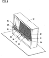
- the storage device comprises a rectangular housing 50 in which a shelf 51 with a specific number of storage locations 52 is located.
- a drawer 10 of the type according to FIG. 1 can be stored in each case. If a drawer 10 is connected to a certain number of attachment elements 30, a corresponding number of storage locations 52 above the drawer 10 are occupied by these attachment elements 30.
- a transport device 55 in the form of a band is mounted for transporting drawers 10 in the direction indicated by the arrows 56 in FIG. Between the two ends 57a and 57b of the conveyor belt 55 there is an externally accessible unloading station 58, from which a drawer 10 can be removed. For feeding into the storage device, a drawer 10 is placed on the conveyor belt 55 at its end 57a.
- the memory device further comprises a robot as a displacement unit 70, which in horizontal and controlled in a vertical direction.
- the robot 70 serves to remove a specific drawer 10 from the shelf 51 and place it on the conveyor belt 55 at the removal station 58.
- a drawer 10 can be picked up by the conveyor belt 55 and moved to a specific storage location 52.
- a weighing station 60 with at least one balance is optionally provided, so that a drawer 10 and the piece goods stored therein can be weighed. This makes it possible to automatically inventory on the stored in the individual drawers 10 piece goods. It is conceivable to provide yet another scale with a different sensitivity so that the weight of both light and heavy piece goods (e.g., paper slips and screws) can be reliably determined.
- light and heavy piece goods e.g., paper slips and screws
- a drawer 10 and the piece goods stored therein are weighed when feeding into the storage device by means of the balance 60 and stored the current value ("actual value") for keeping an inventory in the computer unit.
- the current value can be compared with the value from the previous weighing and the difference can be stored, so that information is available about the total number of units taken.
- the drawer 10 is moved by the robot 70 to a suitable storage location 52.
- the rear wall of the housing where the shelf 51 is located with the storage locations 52, is hinged so that it can be opened similarly to a door and thus open the housing interior, e.g. is accessible externally for maintenance purposes.
- the shelf 51 includes support rails 64 which are secured to the rear wall 67 of the housing 50.
- the distance between two adjacent support rails 64 is slightly larger than the width of the drawer 10 so that it can be pushed in between.
- the depth of a support rail 64 is slightly shorter than the length of a drawer 10, so that the pull-out groove 12 of a drawer 10 stored in a storage space 52 is laterally accessible.
- Both sides of a support rail 64 are provided with retaining grooves 65a and 65b, respectively, into which the retaining bead 19a or 19b of a drawer 10 can be pushed.
- the distance between two adjacent retaining grooves 65a and 65b is slightly larger than the height of a drawer 10, so that in each case a drawer 10 can be pushed into two vertically adjacent memory locations 52.
- the retaining grooves 65a on one side of a support rail 64 are slightly offset with respect to the retaining grooves 65b on the other side of the same support rail 64, so that the width of the support rail 64 is minimized and thus a compact construction of the shelf 51 can be achieved.
- a corresponding profile of light metal such as aluminum is suitable.
- each storage space 52 can be occupied by a drawer 10 or an attachment element 30 be.
- a drawer 10 with three attachment elements 30 and a drawer 10 'with a placement element 30 are located on the shelf 51, wherein two storage spaces 52' are free between them.
- FIG. 5 also shows the displacement unit 70 on which a drawer 10 with a seating element 30 is located.
- the displacement unit 70 has a bottom plate 71 and two parallel side brackets 75a and 75b, between which a drawer 10 can be slid so that the respective retaining bulges 19a and 19b, respectively, on the upper edge of a corresponding side bracket 75a or 75b rests.
- On the bottom plate 71 is an endless belt 76 with a coupling element 77 in the form of, for example, a pin.
- the belt 76 is laid around two spaced apart gears 78a and 78b, at least one of which may be driven.
- the belt 76 is moved counterclockwise, so that the pin 77 is first pushed into the pull-out groove 12 of the drawer 10, whereupon this is taken and then pulled forward until it rests completely on the side brackets 75a, 75b.
- the guiding of the coupling element 77 on a curved path has the advantage that the drawer 10 is displaceable with a slight jerk.
- the coupling element 77 is guided along a circular path, so that the drawer 10 undergoes a substantially sinusoidal acceleration and thus this is not jerky, but gently, especially at the beginning of the movement.
- the displacement unit 70 is movable laterally and vertically between the conveyor belt 55 and the shelf 51.
- the displacement unit 70 is additionally rotatable about a vertical axis, so that a recorded on the displacement unit 70 drawer 10 can be rotated in particular by 180 degrees.
- a drawer 10 can be removed both from the shelf 51 and placed on the conveyor belt 55 and taken from this.
- a computer unit is provided (not shown). This also serves to store and manage information about the individual drawers 10 such as storage space, number of connected Aufsetzrii 30, type and amount of stored cargo, etc.
- the computer unit also monitors the free memory locations 52 and assigns a drawer 10 fed to the memory device to a corresponding memory location 52.
- a sensor unit For detecting the total height of a drawer 10, a sensor unit is provided in the storage device, e.g. in the form of a series of light sensors. From the measured value of the total height, the computer unit can calculate the number of placement elements 30, which are connected to the drawer 10, and thus determine suitable storage locations 54 in the rack 51.
- the storage of piece goods in the storage device takes place as follows:
- the user places the various piece goods in the drawers 10, which are the volume of cargo according to optionally associated with one or more (2004)setzmaschinen 30.
- Data for example About type of cargo, drawer number (corresponding to the barcode), weight of a single piece goods, number of attached Aufsetzmaschine 30, etc. are entered into the computer unit.
- information is stored on which piece goods are stored in which drawer 10.
- the loaded drawers 10 are placed at the feeding station 57a on the conveyor belt 55 and then individually picked up by the displacement unit 70.
- the bar code of the drawer 10 is read and the information is transferred to the computer unit. If a balance is provided, the drawer 10 is moved to the weighing place 60 u.a. for determining the quantity of piece goods contained in a drawer 10. Thereafter, the total height of the drawer 10 is detected and determined by the computer unit, a free space 52, to which the drawer 10 is then transported by means of the displacement unit 70.
- the displacement unit 70 is - controlled by the computer unit - moved to the appropriate storage space 52, the drawer 10 removed and transferred to the conveyor belt 55. After removal of the piece goods, the user feeds the drawer 10 at the feeding station 57a again.
- the computer unit may reorganize the drawers 10 made. Assuming in the example according to FIG. 5, all storage locations 52 are occupied except for the two storage locations 52 'above and below the drawer 10', which is connected to a placement element 30 in FIG. If a drawer 10 with three attachment elements 30 is to be accommodated on the shelf, this drawer 10 'is moved downwards by two storage locations 52', as a result of which four successive storage locations are now free. If it is no longer possible to redesign the stored drawers 10 in such a way that a further drawer 10, which is connected to a certain number of attachment elements 30, can be fed in and stored, the computer unit supplies a corresponding error message.
- the modular structure of the drawers 10 and 30 Aufsetzriin has the advantage that the storage volume of a container can be optimally adapted to the volume of a piece goods. It suffices for the drawers 10 and attachment elements 30 to be produced only in a specific dimension.
- the desired piece goods can be found quickly. It can also be automatically stored and managed the most diverse types of cargo, such as small parts in a workshop (screws, nuts, nails, rings, etc.), files, books, medicines (boxes, pills, blisters, etc.), etc.
Claims (12)
- Dispositif de stockage d'articles, comprenant:au moins un tiroir (10) comme récipient pour contenir des articles;au moins un élément superposable (30) capable d'être relié au tiroir pour augmenter le volume de stockage du tiroir et muni de moyens de liaison (40a, 40b, 41) permettant de le relier à un élément superposable (30) supplémentaire du même genre pour augmenter davantage le volume de stockage; etau moins un rayonnage (51) avec des emplacements de stockage (52) pouvant être occupés chacun par le tiroir ou l'élément superposable.
- Dispositif de stockage selon la revendication 1, caractérisé en ce que l'élément superposable présente la forme d'un cadre (30).
- Dispositif de stockage selon l'une des revendications 1 à 2, caractérisé en ce qu'il comprend une unité de déplacement (70) destinée à recevoir le récipient (10), ladite unité étant déplaçable le long d'au moins deux directions pour déplacer le récipient et préférablement orientable (79) autour d'un axe pour tourner le récipient.
- Dispositif de stockage selon la revendication 3, caractérisé en ce que l'unité de déplacement (70) comprend un élément d'accouplement (77) pouvant être accouplé au récipient (10) et guidé sur une voie incurvée, de sorte que le récipient accouplé à l'élément d'accouplement est déplaçable avec une faible secousse seulement.
- Dispositif de stockage selon l'une des revendications 1 à 4, caractérisé en ce qu'il comprend un dispositif de transport (55) pour alimenter le récipient (10).
- Dispositif de stockage selon l'une des revendications 1 à 5, caractérisé en ce qu'il comprend au moins une balance (60) pour peser le récipient (10) y compris les articles stockés dans celui-ci.
- Dispositif de stockage selon l'une des revendications 1 à 6, caractérisé en ce qu'il comprend une unité de détection pour détecter le nombre d'éléments superposables (30) reliés au récipient (10).
- Procédé de stockage d'articles utilisant le dispositif de stockage selon l'une des revendications 1 à 7, où le volume de stockage du récipient est adapté au volume des articles en reliant le récipient à au moins un élément superposable (30).
- Procédé selon la revendication 8, caractérisé en ce que pour le stockage d'articles de plusieurs types, un nombre de récipients (10) sont chacun pourvus d'une marque distinctive (18) univoque pour les distinguer et stockés dans le rayonnage (51) avec les éléments superposables (30) respectifs y reliés.
- Procédé selon l'une des revendications 8 à 9, caractérisé en ce que les récipients (10) stockés dans le rayonnage (51) sont repositionnés sous la commande d'un ordinateur pour optimiser l'utilisation de l'espace de stockage.
- Procédé selon l'une des revendications 8 à 10, caractérisé en ce que les récipients (10) y compris les articles stockés dans ceux-ci sont pesés pour la tenue automatique d'un inventaire.
- Procédé selon l'une des revendications 8 à 11, caractérisé en ce que le nombre d'éléments superposables (30) reliés au récipient (10) est déterminé.
Priority Applications (3)
| Application Number | Priority Date | Filing Date | Title |
|---|---|---|---|
| AT03405055T ATE328818T1 (de) | 2003-02-04 | 2003-02-04 | Speichervorrichtung und verfahren zum speichern von stueckgut |
| EP03405055A EP1445215B1 (fr) | 2003-02-04 | 2003-02-04 | Dispositif et procédé de stockage d'articles |
| DE50303673T DE50303673D1 (de) | 2003-02-04 | 2003-02-04 | Speichervorrichtung und Verfahren zum Speichern von Stueckgut |
Applications Claiming Priority (1)
| Application Number | Priority Date | Filing Date | Title |
|---|---|---|---|
| EP03405055A EP1445215B1 (fr) | 2003-02-04 | 2003-02-04 | Dispositif et procédé de stockage d'articles |
Publications (2)
| Publication Number | Publication Date |
|---|---|
| EP1445215A1 EP1445215A1 (fr) | 2004-08-11 |
| EP1445215B1 true EP1445215B1 (fr) | 2006-06-07 |
Family
ID=32605481
Family Applications (1)
| Application Number | Title | Priority Date | Filing Date |
|---|---|---|---|
| EP03405055A Expired - Lifetime EP1445215B1 (fr) | 2003-02-04 | 2003-02-04 | Dispositif et procédé de stockage d'articles |
Country Status (3)
| Country | Link |
|---|---|
| EP (1) | EP1445215B1 (fr) |
| AT (1) | ATE328818T1 (fr) |
| DE (1) | DE50303673D1 (fr) |
Families Citing this family (2)
| Publication number | Priority date | Publication date | Assignee | Title |
|---|---|---|---|---|
| DE102006007359A1 (de) | 2006-02-15 | 2007-08-23 | Gollmann Kommissioniersysteme Gmbh | Verfahren einer modifizierten, automatischen, dreidimensionalen Lagerhaltung, insbesondere für Apotheken und Einrichtung zur Durchführung des Verfahrens |
| CN115043167B (zh) * | 2022-08-17 | 2022-10-28 | 江苏环亚医用科技集团股份有限公司 | 方舱医院用物资输送装置 |
Family Cites Families (6)
| Publication number | Priority date | Publication date | Assignee | Title |
|---|---|---|---|---|
| DE2140214A1 (de) * | 1971-08-11 | 1973-03-01 | Breuninger & Groezing Stahlhof | Vollautomatische werkzeugausgabe bei schubladenschraenken |
| GB2088334B (en) * | 1980-12-03 | 1984-08-30 | Cmb Display Group Ltd | Adjustable sized tray for merchandise |
| DE3633171A1 (de) * | 1986-09-30 | 1988-04-07 | Schaefer Gmbh Fritz | Lager- und transportkasten fuer regallager |
| DE9000484U1 (fr) * | 1990-01-18 | 1990-03-22 | Vauth-Sagel Gmbh + Co, 3492 Brakel, De | |
| DE4244713A1 (de) * | 1992-03-02 | 1993-12-23 | Plastorbis Derisen & Mueller G | Transport- und Lagerbehälter |
| AT404124B (de) * | 1997-02-27 | 1998-08-25 | Knapp Holding Gmbh | Stückgut-wechsel-magazin |
-
2003
- 2003-02-04 DE DE50303673T patent/DE50303673D1/de not_active Expired - Lifetime
- 2003-02-04 EP EP03405055A patent/EP1445215B1/fr not_active Expired - Lifetime
- 2003-02-04 AT AT03405055T patent/ATE328818T1/de active
Also Published As
| Publication number | Publication date |
|---|---|
| ATE328818T1 (de) | 2006-06-15 |
| EP1445215A1 (fr) | 2004-08-11 |
| DE50303673D1 (de) | 2006-07-20 |
Similar Documents
| Publication | Publication Date | Title |
|---|---|---|
| DE3213119C2 (de) | Verfahren zum Kommissionieren von Stückgut und Vorrichtung zur Durchführung des Verfahrens | |
| EP1820754B1 (fr) | Système d'étagère et procédé de stockage automatisé de petits objets | |
| DE4318341B4 (de) | Verfahren zur Lagerung von Apotheken-Artikeln und Vorrichtung zur Durchführung eines solchen Verfahrens | |
| EP0620528B1 (fr) | Procédé pour le stockage de colis et dispositif pour la mise en oeuvre de ce procédé | |
| EP2186754B1 (fr) | Installation de préparation et son procédé de fonctionnement avec un chariot de préparation | |
| DE4336885A1 (de) | Kommissionierungsanlage für Apothekenprodukte | |
| EP0847939B1 (fr) | Dispositif et procédé pour rassembler et préparer des marchandises en détail | |
| DE10225332B4 (de) | Einlagerungspuffer und Verfahren zum Einlagern von Stückgütern für ein automatisiertes Stückgutlager | |
| WO2003011722A1 (fr) | Procede et installation pour preparer des commandes a l'aide d'un rayonnage et d'un gerbeur associe | |
| EP2761605A1 (fr) | Dispositif de mise en réserve et de sortie entièrement automatique d'une pluralité de produits | |
| EP1737766A1 (fr) | Dispositif et procede d'approvisionnement de produits empilables | |
| WO2007012099A1 (fr) | Procede et dispositif d'alimentation automatique d'un dispositif de distribution d'articles | |
| EP1423314B1 (fr) | Magasin a rayonnage comportant des tiroirs montes dans les compartiments de rayonnage | |
| DE19941640B4 (de) | Verfahren zur rechnergesteuerten Lagerung von Stückgut und ein zugehöriges Regallagersystem, insbesondere für die Kommissionierung von Arzneimittelpackungen | |
| DE19719651A1 (de) | Verfahren und Vorrichtung zum Kommissionieren | |
| EP1445215B1 (fr) | Dispositif et procédé de stockage d'articles | |
| AT511598B1 (de) | Automatisiertes warenumschlaglager | |
| EP0890329B1 (fr) | Rayonnage avec dispositif de déchargement | |
| EP0416627B1 (fr) | Procédé et dispositif pour stocker et reprendre automatiquement des sortes de marchandises de détail de rayonnages dans de grands entrepôts | |
| DE202008012069U1 (de) | Lagerautomat | |
| EP1370479B1 (fr) | Elevateur de stockage | |
| WO2007012444A1 (fr) | Systeme de stockage a rayonnages comprenant une station d'entree | |
| DE10008362B4 (de) | Regallagersystem, insbesondere für die Kommissionierung von Arzneimittelpackungen | |
| DE10224252A1 (de) | Warenlager- und -ausgabevorrichtung und Bestandserfassungsverfahren hierfür | |
| AT521357B1 (de) | Warenausgabeautomat |
Legal Events
| Date | Code | Title | Description |
|---|---|---|---|
| PUAI | Public reference made under article 153(3) epc to a published international application that has entered the european phase |
Free format text: ORIGINAL CODE: 0009012 |
|
| AK | Designated contracting states |
Kind code of ref document: A1 Designated state(s): AT BE BG CH CY CZ DE DK EE ES FI FR GB GR HU IE IT LI LU MC NL PT SE SI SK TR |
|
| AX | Request for extension of the european patent |
Extension state: AL LT LV MK RO |
|
| 17P | Request for examination filed |
Effective date: 20041217 |
|
| AKX | Designation fees paid |
Designated state(s): AT BE BG CH CY CZ DE DK EE ES FI FR GB GR HU IE IT LI LU MC NL PT SE SI SK TR |
|
| 17Q | First examination report despatched |
Effective date: 20050428 |
|
| GRAP | Despatch of communication of intention to grant a patent |
Free format text: ORIGINAL CODE: EPIDOSNIGR1 |
|
| GRAS | Grant fee paid |
Free format text: ORIGINAL CODE: EPIDOSNIGR3 |
|
| GRAA | (expected) grant |
Free format text: ORIGINAL CODE: 0009210 |
|
| AK | Designated contracting states |
Kind code of ref document: B1 Designated state(s): AT BE BG CH CY CZ DE DK EE ES FI FR GB GR HU IE IT LI LU MC NL PT SE SI SK TR |
|
| PG25 | Lapsed in a contracting state [announced via postgrant information from national office to epo] |
Ref country code: IT Free format text: LAPSE BECAUSE OF FAILURE TO SUBMIT A TRANSLATION OF THE DESCRIPTION OR TO PAY THE FEE WITHIN THE PRESCRIBED TIME-LIMIT;WARNING: LAPSES OF ITALIAN PATENTS WITH EFFECTIVE DATE BEFORE 2007 MAY HAVE OCCURRED AT ANY TIME BEFORE 2007. THE CORRECT EFFECTIVE DATE MAY BE DIFFERENT FROM THE ONE RECORDED. Effective date: 20060607 Ref country code: SI Free format text: LAPSE BECAUSE OF FAILURE TO SUBMIT A TRANSLATION OF THE DESCRIPTION OR TO PAY THE FEE WITHIN THE PRESCRIBED TIME-LIMIT Effective date: 20060607 Ref country code: FI Free format text: LAPSE BECAUSE OF FAILURE TO SUBMIT A TRANSLATION OF THE DESCRIPTION OR TO PAY THE FEE WITHIN THE PRESCRIBED TIME-LIMIT Effective date: 20060607 Ref country code: NL Free format text: LAPSE BECAUSE OF FAILURE TO SUBMIT A TRANSLATION OF THE DESCRIPTION OR TO PAY THE FEE WITHIN THE PRESCRIBED TIME-LIMIT Effective date: 20060607 Ref country code: IE Free format text: LAPSE BECAUSE OF FAILURE TO SUBMIT A TRANSLATION OF THE DESCRIPTION OR TO PAY THE FEE WITHIN THE PRESCRIBED TIME-LIMIT Effective date: 20060607 Ref country code: SK Free format text: LAPSE BECAUSE OF FAILURE TO SUBMIT A TRANSLATION OF THE DESCRIPTION OR TO PAY THE FEE WITHIN THE PRESCRIBED TIME-LIMIT Effective date: 20060607 Ref country code: GB Free format text: LAPSE BECAUSE OF FAILURE TO SUBMIT A TRANSLATION OF THE DESCRIPTION OR TO PAY THE FEE WITHIN THE PRESCRIBED TIME-LIMIT Effective date: 20060607 Ref country code: CZ Free format text: LAPSE BECAUSE OF FAILURE TO SUBMIT A TRANSLATION OF THE DESCRIPTION OR TO PAY THE FEE WITHIN THE PRESCRIBED TIME-LIMIT Effective date: 20060607 |
|
| REG | Reference to a national code |
Ref country code: GB Ref legal event code: FG4D Free format text: NOT ENGLISH |
|
| REG | Reference to a national code |
Ref country code: CH Ref legal event code: EP |
|
| REG | Reference to a national code |
Ref country code: CH Ref legal event code: NV Representative=s name: AMMANN PATENTANWAELTE AG BERN |
|
| REG | Reference to a national code |
Ref country code: IE Ref legal event code: FG4D Free format text: LANGUAGE OF EP DOCUMENT: GERMAN |
|
| REF | Corresponds to: |
Ref document number: 50303673 Country of ref document: DE Date of ref document: 20060720 Kind code of ref document: P |
|
| PG25 | Lapsed in a contracting state [announced via postgrant information from national office to epo] |
Ref country code: SE Free format text: LAPSE BECAUSE OF FAILURE TO SUBMIT A TRANSLATION OF THE DESCRIPTION OR TO PAY THE FEE WITHIN THE PRESCRIBED TIME-LIMIT Effective date: 20060907 Ref country code: DK Free format text: LAPSE BECAUSE OF FAILURE TO SUBMIT A TRANSLATION OF THE DESCRIPTION OR TO PAY THE FEE WITHIN THE PRESCRIBED TIME-LIMIT Effective date: 20060907 |
|
| PG25 | Lapsed in a contracting state [announced via postgrant information from national office to epo] |
Ref country code: ES Free format text: LAPSE BECAUSE OF FAILURE TO SUBMIT A TRANSLATION OF THE DESCRIPTION OR TO PAY THE FEE WITHIN THE PRESCRIBED TIME-LIMIT Effective date: 20060918 |
|
| PG25 | Lapsed in a contracting state [announced via postgrant information from national office to epo] |
Ref country code: PT Free format text: LAPSE BECAUSE OF FAILURE TO SUBMIT A TRANSLATION OF THE DESCRIPTION OR TO PAY THE FEE WITHIN THE PRESCRIBED TIME-LIMIT Effective date: 20061107 |
|
| NLV1 | Nl: lapsed or annulled due to failure to fulfill the requirements of art. 29p and 29m of the patents act | ||
| GBV | Gb: ep patent (uk) treated as always having been void in accordance with gb section 77(7)/1977 [no translation filed] |
Effective date: 20060607 |
|
| REG | Reference to a national code |
Ref country code: IE Ref legal event code: FD4D |
|
| PG25 | Lapsed in a contracting state [announced via postgrant information from national office to epo] |
Ref country code: MC Free format text: LAPSE BECAUSE OF NON-PAYMENT OF DUE FEES Effective date: 20070228 |
|
| PLBE | No opposition filed within time limit |
Free format text: ORIGINAL CODE: 0009261 |
|
| STAA | Information on the status of an ep patent application or granted ep patent |
Free format text: STATUS: NO OPPOSITION FILED WITHIN TIME LIMIT |
|
| EN | Fr: translation not filed | ||
| 26N | No opposition filed |
Effective date: 20070308 |
|
| BERE | Be: lapsed |
Owner name: PROMATEC AUTOMATION A.G. Effective date: 20070228 |
|
| PG25 | Lapsed in a contracting state [announced via postgrant information from national office to epo] |
Ref country code: BE Free format text: LAPSE BECAUSE OF NON-PAYMENT OF DUE FEES Effective date: 20070228 |
|
| PG25 | Lapsed in a contracting state [announced via postgrant information from national office to epo] |
Ref country code: GR Free format text: LAPSE BECAUSE OF FAILURE TO SUBMIT A TRANSLATION OF THE DESCRIPTION OR TO PAY THE FEE WITHIN THE PRESCRIBED TIME-LIMIT Effective date: 20060908 Ref country code: FR Free format text: LAPSE BECAUSE OF FAILURE TO SUBMIT A TRANSLATION OF THE DESCRIPTION OR TO PAY THE FEE WITHIN THE PRESCRIBED TIME-LIMIT Effective date: 20070309 |
|
| PG25 | Lapsed in a contracting state [announced via postgrant information from national office to epo] |
Ref country code: BG Free format text: LAPSE BECAUSE OF FAILURE TO SUBMIT A TRANSLATION OF THE DESCRIPTION OR TO PAY THE FEE WITHIN THE PRESCRIBED TIME-LIMIT Effective date: 20060907 |
|
| PG25 | Lapsed in a contracting state [announced via postgrant information from national office to epo] |
Ref country code: EE Free format text: LAPSE BECAUSE OF FAILURE TO SUBMIT A TRANSLATION OF THE DESCRIPTION OR TO PAY THE FEE WITHIN THE PRESCRIBED TIME-LIMIT Effective date: 20060607 |
|
| PG25 | Lapsed in a contracting state [announced via postgrant information from national office to epo] |
Ref country code: FR Free format text: LAPSE BECAUSE OF FAILURE TO SUBMIT A TRANSLATION OF THE DESCRIPTION OR TO PAY THE FEE WITHIN THE PRESCRIBED TIME-LIMIT Effective date: 20060607 |
|
| PG25 | Lapsed in a contracting state [announced via postgrant information from national office to epo] |
Ref country code: CY Free format text: LAPSE BECAUSE OF FAILURE TO SUBMIT A TRANSLATION OF THE DESCRIPTION OR TO PAY THE FEE WITHIN THE PRESCRIBED TIME-LIMIT Effective date: 20060607 Ref country code: LU Free format text: LAPSE BECAUSE OF NON-PAYMENT OF DUE FEES Effective date: 20070204 |
|
| PG25 | Lapsed in a contracting state [announced via postgrant information from national office to epo] |
Ref country code: HU Free format text: LAPSE BECAUSE OF FAILURE TO SUBMIT A TRANSLATION OF THE DESCRIPTION OR TO PAY THE FEE WITHIN THE PRESCRIBED TIME-LIMIT Effective date: 20061208 Ref country code: TR Free format text: LAPSE BECAUSE OF FAILURE TO SUBMIT A TRANSLATION OF THE DESCRIPTION OR TO PAY THE FEE WITHIN THE PRESCRIBED TIME-LIMIT Effective date: 20060607 |
|
| REG | Reference to a national code |
Ref country code: DE Ref legal event code: R082 Ref document number: 50303673 Country of ref document: DE Representative=s name: MAI DOERR BESIER PATENTANWAELTE, DE |
|
| PGFP | Annual fee paid to national office [announced via postgrant information from national office to epo] |
Ref country code: DE Payment date: 20150219 Year of fee payment: 13 Ref country code: CH Payment date: 20150225 Year of fee payment: 13 |
|
| PGFP | Annual fee paid to national office [announced via postgrant information from national office to epo] |
Ref country code: AT Payment date: 20150219 Year of fee payment: 13 |
|
| REG | Reference to a national code |
Ref country code: DE Ref legal event code: R119 Ref document number: 50303673 Country of ref document: DE |
|
| REG | Reference to a national code |
Ref country code: CH Ref legal event code: PL |
|
| REG | Reference to a national code |
Ref country code: AT Ref legal event code: MM01 Ref document number: 328818 Country of ref document: AT Kind code of ref document: T Effective date: 20160204 |
|
| PG25 | Lapsed in a contracting state [announced via postgrant information from national office to epo] |
Ref country code: LI Free format text: LAPSE BECAUSE OF NON-PAYMENT OF DUE FEES Effective date: 20160229 Ref country code: CH Free format text: LAPSE BECAUSE OF NON-PAYMENT OF DUE FEES Effective date: 20160229 |
|
| PG25 | Lapsed in a contracting state [announced via postgrant information from national office to epo] |
Ref country code: AT Free format text: LAPSE BECAUSE OF NON-PAYMENT OF DUE FEES Effective date: 20160204 |
|
| PG25 | Lapsed in a contracting state [announced via postgrant information from national office to epo] |
Ref country code: DE Free format text: LAPSE BECAUSE OF NON-PAYMENT OF DUE FEES Effective date: 20160901 |