EP0890124B1 - Method for connecting optical fibers - Google Patents
Method for connecting optical fibers Download PDFInfo
- Publication number
- EP0890124B1 EP0890124B1 EP97908703A EP97908703A EP0890124B1 EP 0890124 B1 EP0890124 B1 EP 0890124B1 EP 97908703 A EP97908703 A EP 97908703A EP 97908703 A EP97908703 A EP 97908703A EP 0890124 B1 EP0890124 B1 EP 0890124B1
- Authority
- EP
- European Patent Office
- Prior art keywords
- fiber
- splice
- fibers
- splice element
- actuation
- Prior art date
- Legal status (The legal status is an assumption and is not a legal conclusion. Google has not performed a legal analysis and makes no representation as to the accuracy of the status listed.)
- Expired - Lifetime
Links
- 238000000034 method Methods 0.000 title claims description 28
- 239000013307 optical fiber Substances 0.000 title claims description 14
- 239000000835 fiber Substances 0.000 claims description 186
- 239000000463 material Substances 0.000 claims description 24
- 230000008569 process Effects 0.000 claims description 14
- 230000001351 cycling effect Effects 0.000 claims description 10
- 238000010438 heat treatment Methods 0.000 claims description 10
- 238000001816 cooling Methods 0.000 claims description 7
- 238000012360 testing method Methods 0.000 description 33
- XAGFODPZIPBFFR-UHFFFAOYSA-N aluminium Chemical compound [Al] XAGFODPZIPBFFR-UHFFFAOYSA-N 0.000 description 15
- 238000007906 compression Methods 0.000 description 14
- 230000006835 compression Effects 0.000 description 13
- 229910052782 aluminium Inorganic materials 0.000 description 12
- 238000003780 insertion Methods 0.000 description 12
- 230000037431 insertion Effects 0.000 description 12
- 230000003287 optical effect Effects 0.000 description 12
- 230000007704 transition Effects 0.000 description 12
- 239000011521 glass Substances 0.000 description 11
- 238000005259 measurement Methods 0.000 description 11
- 238000005498 polishing Methods 0.000 description 8
- 230000036316 preload Effects 0.000 description 7
- 230000007480 spreading Effects 0.000 description 6
- 238000003892 spreading Methods 0.000 description 6
- RYGMFSIKBFXOCR-UHFFFAOYSA-N Copper Chemical compound [Cu] RYGMFSIKBFXOCR-UHFFFAOYSA-N 0.000 description 4
- 238000005452 bending Methods 0.000 description 4
- 230000008859 change Effects 0.000 description 4
- 229910052802 copper Inorganic materials 0.000 description 4
- 239000010949 copper Substances 0.000 description 4
- 230000003247 decreasing effect Effects 0.000 description 4
- 238000012986 modification Methods 0.000 description 4
- 230000004048 modification Effects 0.000 description 4
- 230000007547 defect Effects 0.000 description 3
- 239000004744 fabric Substances 0.000 description 3
- 239000003365 glass fiber Substances 0.000 description 3
- 229910052751 metal Inorganic materials 0.000 description 3
- 238000000253 optical time-domain reflectometry Methods 0.000 description 3
- 238000012935 Averaging Methods 0.000 description 2
- KFZMGEQAYNKOFK-UHFFFAOYSA-N Isopropanol Chemical compound CC(C)O KFZMGEQAYNKOFK-UHFFFAOYSA-N 0.000 description 2
- 230000008901 benefit Effects 0.000 description 2
- 230000008878 coupling Effects 0.000 description 2
- 238000010168 coupling process Methods 0.000 description 2
- 238000005859 coupling reaction Methods 0.000 description 2
- 230000004927 fusion Effects 0.000 description 2
- 238000000227 grinding Methods 0.000 description 2
- 230000007246 mechanism Effects 0.000 description 2
- 239000002184 metal Substances 0.000 description 2
- 230000009467 reduction Effects 0.000 description 2
- 229920000106 Liquid crystal polymer Polymers 0.000 description 1
- 239000004977 Liquid-crystal polymers (LCPs) Substances 0.000 description 1
- 230000005540 biological transmission Effects 0.000 description 1
- 238000009529 body temperature measurement Methods 0.000 description 1
- 238000005253 cladding Methods 0.000 description 1
- 238000004891 communication Methods 0.000 description 1
- 230000008602 contraction Effects 0.000 description 1
- 230000002939 deleterious effect Effects 0.000 description 1
- 230000001419 dependent effect Effects 0.000 description 1
- 230000000694 effects Effects 0.000 description 1
- 230000005489 elastic deformation Effects 0.000 description 1
- 229940085805 fiberall Drugs 0.000 description 1
- 230000014759 maintenance of location Effects 0.000 description 1
- 238000004519 manufacturing process Methods 0.000 description 1
- 238000002844 melting Methods 0.000 description 1
- 230000008018 melting Effects 0.000 description 1
- 238000005065 mining Methods 0.000 description 1
- 239000000203 mixture Substances 0.000 description 1
- 239000005304 optical glass Substances 0.000 description 1
- 238000002360 preparation method Methods 0.000 description 1
- 238000011160 research Methods 0.000 description 1
- 239000000523 sample Substances 0.000 description 1
- 238000000926 separation method Methods 0.000 description 1
- 239000000126 substance Substances 0.000 description 1
- 238000012956 testing procedure Methods 0.000 description 1
- 238000012546 transfer Methods 0.000 description 1
Images


Classifications
-
- G—PHYSICS
- G02—OPTICS
- G02B—OPTICAL ELEMENTS, SYSTEMS OR APPARATUS
- G02B6/00—Light guides; Structural details of arrangements comprising light guides and other optical elements, e.g. couplings
- G02B6/24—Coupling light guides
- G02B6/36—Mechanical coupling means
- G02B6/38—Mechanical coupling means having fibre to fibre mating means
- G02B6/3801—Permanent connections, i.e. wherein fibres are kept aligned by mechanical means
- G02B6/3802—Assembly tools, e.g. crimping tool or pressing bench
-
- G—PHYSICS
- G02—OPTICS
- G02B—OPTICAL ELEMENTS, SYSTEMS OR APPARATUS
- G02B6/00—Light guides; Structural details of arrangements comprising light guides and other optical elements, e.g. couplings
- G02B6/24—Coupling light guides
- G02B6/36—Mechanical coupling means
- G02B6/38—Mechanical coupling means having fibre to fibre mating means
- G02B6/3801—Permanent connections, i.e. wherein fibres are kept aligned by mechanical means
- G02B6/3803—Adjustment or alignment devices for alignment prior to splicing
- G02B6/3805—Adjustment or alignment devices for alignment prior to splicing with a fibre-supporting member inclined to the bottom surface of the alignment means
-
- G—PHYSICS
- G02—OPTICS
- G02B—OPTICAL ELEMENTS, SYSTEMS OR APPARATUS
- G02B6/00—Light guides; Structural details of arrangements comprising light guides and other optical elements, e.g. couplings
- G02B6/24—Coupling light guides
- G02B6/36—Mechanical coupling means
- G02B6/38—Mechanical coupling means having fibre to fibre mating means
- G02B6/3807—Dismountable connectors, i.e. comprising plugs
- G02B6/381—Dismountable connectors, i.e. comprising plugs of the ferrule type, e.g. fibre ends embedded in ferrules, connecting a pair of fibres
- G02B6/3818—Dismountable connectors, i.e. comprising plugs of the ferrule type, e.g. fibre ends embedded in ferrules, connecting a pair of fibres of a low-reflection-loss type
- G02B6/382—Dismountable connectors, i.e. comprising plugs of the ferrule type, e.g. fibre ends embedded in ferrules, connecting a pair of fibres of a low-reflection-loss type with index-matching medium between light guides
Definitions
- This invention relates to an improved method for the interconnection of optical fibers and in one aspect relates to a new "dry,” i.e. gel-less, mechanical optical fiber interconnection where the fiber ends are optically aligned and are pressed together and maintained under axial compression by the splicing element.
- Optical fiber splices are well known and the art is becoming crowded with elements for aligning the fiber ends optically and holding the same in alignment. Cleaved fiber ends are used in most mechanical splices currently available. These splices contain a coupling medium, usually a gel or oil, that has the same index of refraction as the core of the fiber. This index matching material is used to fill the gap between the pair of fiber end faces which are to be spliced.
- a coupling medium usually a gel or oil
- Mechanical splices all contain the index matching gel materials. Some mechanical splices have a problem with temperature cycling due to the index of refraction of these materials changing at varying temperatures, which result in fluctuations of the optical signal, mainly return loss increases. Therefore, the mechanical splices, not using angled cleaving on the fiber ends, presented a problem, first, in not always meeting temperature cycling specifications and, second, needing the index matching materials. However, the mechanical splices are easier for
- EP-A-0 524 079, EP-A-0 029 383, and EP-A-0 122 169 each discloses a process for splicing optical fibers.
- the fibers are inserted in a fiber alignment passageway of a splice element and the splice element is actuated about the fibers by actuating a clamp member which maintains an axial compressive force at the interface of the fiber cores.
- Mechanical splices all contain the index matching gel materials. Some mechanical splices have a problem with temperature cycling due to the index of refraction of these materials changing at varying temperatures, which result in fluctuations of the optical signal, mainly return loss increases. Therefore, the mechanical splices, not using angled cleaving on the fiber ends, presented a problem, first, in not always meeting temperature cycling specifications and, second, needing the index matching materials. However, the mechanical splices are easier to the technician in the field to complete.
- the present invention provides a new and improved process for splicing optical fibers.
- the process comprises the steps as set out in claim 1. Stress is applied to the splice element by heating the splice element, prior to the insertion of the fiber ends into the splice element and actuating the same, wherein the thermal coefficent of expansion of the splice element is larger than that of the fibers. Further, in addition to heating the splice element the fiber ends can be placed in the splice element under spring or mechanically applied compression contact.
- the amount of heat applied exceeds the temperature used in the temperature cycling tests of the Bellcore specification, as used generally industry wide and published by Bellcore (Bell Communications Research, Morristown, NJ) Document TA-NWT-000765 and GR-765.
- force can be applied to the element to distort or stress the material and cause the material to apply compressive stress on the fibers to force them into compressive contact.
- the interconnection resulting from the present invention is an optical splice between two single mode optical fibers comprising a splice element having a longitudinal passageway for receiving the ends of the fibers approximate the midpoint of the passageway, and the fiber ends being placed in axial compression against each other free of any index matching material.
- the splice process of the present invention contemplates splicing two optical fiber ends which have been positioned and clamped within a metal splice element. Through one of a variety of methods, the fiber ends are placed and held in optically aligned intimate axial compression against each other.
- the splice made according to the present invention is free of any index matching material.
- the present invention provides a novel method of obtaining a splice.
- like reference numerals are used to identify like parts throughout the several views.
- Cleaving is a practice of first scoring or nicking a very small point on the outer periphery of the cladding of an optical glass fiber, which reduces its mechanical strength at that point.
- the later application of a tensile or bending load along the length of the fiber where the score defect was made causes the fiber to break generally perpendicular to the fiber axis.
- the cleaving procedure creates the fiber end face 8, see Figure 1, which possesses the most, easily obtainable defect free surface mechanically obtainable for the fiber core 9.
- Undesirable features caused by the cleaving process can be removed by grinding a bevel on the end of the fiber.
- the conical geometry of the bevel 13 which has been ground on the end of a single mode fiber are easily generated by using existing tools which are operated both manually and automatically.
- One such tool for bevel grinding is described in WO-A-95/07794. March 1995, of Minnesota Mining and Manufacturing Company.
- a bevel angle or included angle, of the cone shaped end portion 13, of between 40 and 160 degrees can be easily obtained by making simple adjustments to the tools.
- the change in angle provides a change in the end face diameters.
- the fiber length is easily set with a simple fixture, and once set, the angles generated are consistent from fiber to fiber, within a range window of 10 degrees.
- the end face area or its diameter is determined by the amount of material removed from the end of the fiber. On the automatic bevel tool, this is controlled by the amount of time the fiber is ground. The more time spent results in a smaller end face diameter. On the manual bevel tool, this is controlled by the number of revolutions the fiber is rotated against the abrasive media, more revolutions results in a smaller end face diameter. Control of the end face diameter is very consistent once the tool parameters have been set. End face diameter can usually be maintained within + or - 5.1 ⁇ m (0.0002 inch), over many beveling cycles before the abrasive media requires changing due to wear. The surface area of the end face of a fiber is greatly reduced by beveling the end of a fiber.
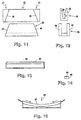
- Figure 5 illustrates this reduction by comparing a cleaved fiber 15 next to a cleaved and beveled fiber 16.
- the reduction in surface area is important for two reasons.
- the second reason involves the amount of axial pressure required to elastically deform both fiber end faces to the point that the fiber cores 9 are in intimate contact, and a gap does not exist between them. If pressure on a fiber remains constant, and the surface area of the fiber's end face is reduced, the total pressure experienced at the fiber interface increases. This benefit, i.e., increasing fiber end interface pressure to afford intimate pressure axial contact between the fiber cores, is important. The amount of force that can be transmitted down a length of 250 micron buffer coated fiber all the way to its end face is very small. Using a standard 38.1mm (1.500 inch) long FibrlokTM Splice as an example, the fiber is inserted 1/2 way into the splice, which would be a distance of 19mm (0.750 inch).
- the diameter of the glass portion of a 250 micron fiber measures 0.125mm (0.005 inch) . This is a poor length to diameter ratio (150 to 1) for the transmission of force.
- the splice entrance hole is several thousands of an inch larger than the outside diameter of the fiber, to provide clearance, which allows the fiber to bend when put under axial pressure. If this pressure is too great, the fiber buckles, and damage or breakage can occur.
- polishing can be obtained by heat polishing or abrasive polishing. Heat polishing means the melting of the fiber surface and abrasive polishing involves the removal of glass with an abrasive media.
- abrasive polishing which leaves scratches in the end face of the fiber. Finer and finer abrasive grits are used to reduce the size and depth of these scratches, improving surface finish, but scratches will always remain. The finer the finish desired, the more polishing steps required, which means more time required.
- Optical fiber splices are expected, by most customers, to meet standard Bellcore performance specifications. Limits are prescribed for return loss throughout a temperature range of -40°C to 80°C. Typical splices, which contain optical index matching materials, display poor return loss at and near these temperature extremes. Intimate contact should be maintained between 0°C and 40°C for indoor applications.
- FibrlokTM Splices were made in the factory without the application of index matching gel and/or oil, a "dry" splice.
- a pair of 125 micron single mode fibers were stripped and cleaved, within 1 degree of being perpendicular.
- the fibers were then beveled with 90 degree included angles, and 0.04 mm (0.0015 inch) diameter end faces, similar to the fiber 16 illustrated in Figure 5. They were cleaned by moistening a lint free cloth with isopropanol, surrounding the fiber with the cloth, pulling it out, and finally making several wipes of the tip of the fiber against the cloth.
- the fibers were then inserted into the splice using the standard established procedures, and then the splice was actuated.
- a Textronics FibermasterTM OTDR was used to measure splice performance during all tests. Measurements were made by averaging the readings taken from both fibers, one at each end of the splice, for greater accuracy. Several splice samples were made at room temperature, 26 degrees C., and results were similar for all samples. Insertion loss was below -0.2dB, and return loss, (backreflection), ranged from -20dB to -45dB. The splices were put into a temperature cycling chamber and put through a Bellcore patterned temperature test, -40°C to 80°C. One hour at each temperature with an hour and a half transition time between temperatures.
- the FibrlokTM Element is made from aluminum.
- the thermal coefficient of expansion for aluminum is 0.0000238 per unit length per degree C. That number for glass can be between 0.0000102 and 0.00000005, depending on its chemical composition. Aluminum will therefore expand and contract at a faster rate than glass.
- the FibrlokTM element grips the glass fibers upon actuation. The fibers are actually lightly embedded in the elements surfaces, and no slippage occurs between the fibers and the element.
- the fiber ends were placed into light nominal contact with each other, without fiber end face deformation, using the standard splice assembly procedure which uses forces generated from bowing the buffer section of the fiber outside of the splice to ensure fiber end face contact is made inside the splice.
- the temperature inside the thermal test chamber increased above the temperature at which the splices were assembled, the aluminum element was expanding at a faster rate than the glass fiber, until all pressure at the fiber interface had been relieved and the fibers started to separate.
- high return losses are measured due to the glass/air/glass interface. This condition reversed itself when the thermal chamber temperature dropped below the splice assembly temperature.
- the aluminum element contracted at a faster rate than the glass fiber, resulting in increased pressure at the fiber interface, reducing and eliminating the glass/air/glass interface yielding lower return loss readings.
- the return loss pattern remained consistent from one cycle to the next.
- the present process involves heating a dry FibrlokTM Splice to a temperature that was higher than the highest temperature that the splice would ever be subjected to, inserting the fibers into the "hot” splice, and actuating it. This should ensure that the fiber end faces are always in intimate contact within the target operating temperatures, which would yield low return losses.
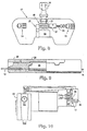
- a commercial FibrlokTM Splice Actuation Tool 17 was modified as illustrated in Figure 6 to apply heat to the splice.
- the plastic splice retention nest was machined off the base of the tool, and replaced by a new nest 20 made from aluminum which housed two 3.17mm (1/8 inch) diameter by 25.4mm (1 inch) long, electrically powered, 25 watt cartridge heaters 21 and 22.
- the heaters were controlled by a Ogden digital control, accurate to +/1 degree C.
- the splice nest was designed to surround as much of the splice as possible without affecting its function, in order to transfer heat to the splice as fast as possible.
- thermocouple was placed inside the center of a metallic FibrlokTM splice element, it was assembled into a splice, and the splice placed into the modified tool.
- the splice was heated four separate times, from room temperature to 100°C.
- the average time for the splice element to reach the target temperature was 50 seconds.
- the splice was removed from the tool, it required from three to four minutes for the splice element to cool back to room temperature.
- the splice was tested and the temperature control for the first splice test was set at 100°C, 20 degrees higher than the highest temperature specified in the Bellcore testing procedure.
- a dry FibrlokTM Splice was inserted into the heated aluminum nest and allowed to soak at a temperature of 100°C for a minute.
- a pair of fibers were cleaved, within 1 degree, and beveled to an end face diameter of 0.05 mm (0.002 inch).
- the fibers were inserted into the heated splice, the splice was actuated, allowed to cool, and placed into the temperature testing chamber.
- the first performance measurements taken at room temperature showed insertion loss was -0.10dB with a total fluctuation of 0.02dB. Average return loss was -56.7dB with a total fluctuation of 3.7 dB.
- the normal buffered fiber restraints 23 and the actuating lever 24 remained on the tool 17.
- a second tool modification is shown in Figure 8, where a fixed clamping mechanism 25 was attached to the actuating tool 17 at the left side of the splice nest 20, and positioned to grip the fiber immediately as it exited the splice.
- a second fiber clamp 27 was mounted at the right side of the splice nest 20 on a linear ball slide with approximately 2.5 mm (0.1 inch) travel.
- a compression spring was in contact with the ball slide, and located opposite the splice rest 20.
- a screw 26 was mounted on the tool base and was used for adjusting the force that the compression spring placed on the fiber via the ball slide.
- a dry FibrlokTM Splice was placed into the tool, and a pair of fibers were prepared having a cleave angle of less than 1 degree, and bevel diameters of 0.038 mm (0.0015 inch) on each fiber end.
- the tool was heated to 100°C one of the fibers was placed into the left hand side of the splice approximately half way, and then clamped.
- the second fiber was placed into the right hand side of the splice until it made contact with the first fiber, and was then clamped.
- the force adjustment screw was rotated until approximately 1.3 Newtons (0.3 pounds) of compressive force was generated, and then the splice was actuated to clamp the fiber ends. Both clamps were then released.
- the added axial pressure of the compression spring fiber preloading increased the temperature at which the fibers separated, while keeping the return losses at the colder temperatures comparable to previous tests.
- the optical signal remained fairly stable within the Bellcore operating temperature test range.
- a dry FibrlokTM Splice was placed into the tool nest which remained at room temperature.
- a pair of fibers were prepared with less than 1° cleave angle, and bevel diameters of 0.038 mm (0.0015 inch). The fibers were gripped in the clamps like the previous test. Approximately 0.9 Newtons (0.2 pound) of compressive force was applied to the right side fiber, then the splice was actuated and all clamping forces were removed.
- the fiber end face transition zone for heating was between 129° and 134°C.
- the transition zone for cooling was between 114° and 120°C. After the first heating cycle, all remaining cycle patterns were very consistent with one another inside of the Bellcore operating temperature test range.
- the body 28 and cap 29 of the FibrlokTM Splice shown in Figure 9 is formed of a liquid crystal polymer with 30% glass loading and can withstand the temperatures described above without deleterious effect and the splice element 30 is formed of aluminum.
- FIG. 10 A further modification of the actuation tool 17 is shown in Figure 10.
- the modification was the addition of a force gauge 34 placed next to the left side of the splice nest 20 opposite to the fixed fiber clamping tool 25.
- the force gauge measurement probe pushed on one end of a pivot arm which in turn pushed on the moveable fiber clamp.
- the pivot was positioned in such a manner to reduce the forces generated by the force gauge/linear slide assembly by a ratio of 10 to 1. This will improve the accuracy of the force measurement on the movable fiber in making a splice.
- the cycle pattern was accelerated to a four hour complete cycle, starting with: (1) 1/2 hour at -40°C, (2) 1 1/2 hours transition time from -40°C to 80°C, (3) 1/2 hour at 80°C, (4) 1 1/2 hours transition time from 80°C to -40°C, continuously repeating.
- the purpose of this test was to verify that dry fiber interfaces could survive many repetitions of the Bellcore temperature test pattern, and to investigate consistency of the optical signal from start to finish.
- Four splices assembled with this fixture endured 530 complete cycles, taking approximately 89 days. Measurements were made with the OTDR by averaging the readings taken from both fibers, one at each end of the splice, for greater accuracy.
- Splices 1 and 2 had a beveled fiber to beveled fiber interface, while splices 3 and 4 had a beveled fiber to a cleaved fiber interface.
- Splice 1 possessed 0.038mm (0.0015 inch) diameter end faces and was assembled at 0.9 Newtons (0.22 pounds) of fiber preload force.
- Total return loss variation was 9.5dB, while insertion loss variation was 0.05dB.
- Splice 2 possessed 0.038 mm (0.0015 inch) diameter end faces and was assembled at 0.89 Newtons (0.2 pound) of fiber preload force. The total return loss variation was 14dB, while insertion loss variation was 0.05dB.
- Splice 3 possessed one 0.038mm (0.0015 inch) diameter end face and was assembled at 1.33 Newtons (0.3 pound) of fiber preload force. Total return loss variation was 31dB, while insertion loss variation was 0.11dB. Splice 4 possessed one 0.025 mm (0.001 inch) diameter end face and was assembled at 0.445 Newtons (0.1 pound) of fiber preload force. Total loss variation was 6dB, while insertion loss variation was 0.05dB. Except for splice 3, the results demonstrated good, stable optical signals with no change in performance from beginning of the test, to its end. Splice 3 performed poorly at the higher temperatures. Upon closer examination with the OTDR, it was discovered that at 80°C the fiber end face transition zone had been reached. During some of the cycles, the end faces would stay in contact yielding excellent return loss, while in others they would separate towards the end of the 80°C time period, yielding poorer return loss.
- Increments as low as several thousandths of a pound were used at the beginning, where several hundredths of a pound (a tenth of a Newton or less) worked well during the latter stages of the test.
- Several trials were made with each splice and fiber pair, and several tests were conducted using different fiber pairs. The results from the tests were substantially the same. The lowest return losses usually occurred between 0.05 and 0.1 Newton (0.012 and 0.026 pound).
- FibrlokTM Splice, splice element is made from a material other than aluminum, having a coefficient of thermal expansion closer to glass, return loss performance should improve, using the fiber compression process prior to actuation of the splice.
- materials available that are as ductile and cost effective as aluminum. Copper was close, and was chosen to test this theory.
- the coefficient of thermal expansion for copper is 0.0000141 per unit length per degree C., as compared to aluminum which is 0.0000238.
- Several elements were made, and a dry copper splice was assembled. A pair of fibers were cleaved and beveled to a 0.043mm (0.0017 inch) diameter end face. The fiber end faces were preloaded to 1.1 Newton 0.25 pounds and the splice was actuated.
- Optical fibers that are prepared using a quality cleaving process and the application of bevel geometry on one or both fibers, coupled with the generation of compressive forces at the fiber interface by the use of either heat or pressure, or both, inside of a "dry," i.e. gel-less, FibrlokTM Splice, can yield stable return loss and insertion loss performance, equivalent to fusion splices, during Bellcore temperature cycling tests without the use of index matching materials.
- Figure 11 diagrammatically illustrates a modified splice element 35 comparable to the FibrlokTM splice element, modified to remove material along the sides and form cam surfaces 36 adjacent each end, which cam surfaces are angularly related to the axis of the fiber passageway 38, see Figure 12.
- the actuation tool is modified to have a spreading cam 39 formed thereon.
- the spreading cam 39 is formed with cam surfaces 40 which are formed to engage the cam surfaces 36 to stretch the splice element 35 upon the application of force on the splice element 35 as illustrated by the arrows 41.
- the length of the elastic deformation of the splice element, in the longitudinal direction, is controlled by the distance the splice element is forced down upon the spreading cam 39.
- the cam surfaces on the element could be designed to shear at a selected force which would result in the desired extension.
- the element is closed to clamp the fibers in place, and the spreading force placed previously on the element is removed. With the removal of the spreading force, stored energy in the element causes a contraction of the element 35, placing the opposed optically aligned ends of the fibers in longitudinal compression or intimate axial contact.
- Figure 12 diagrammatically shows the end view of the modified element 35 and the spreading cam 39.
- Figures 13 and 14 illustrate a further modification wherein a splice element 45 is rectangular having a longitudinal V-groove 46 along the upper surface and the ends of the fibers are placed in the V-groove in firm contact near the longitudinal center of the splice element 45 and of the V-groove 46. The fibers are then firmly secured at the opposite ends of the longitudinal groove. While fixing the position of the ends of the element within a housing, a force 48, see Figure 15, is applied normal to the top surface of the element 45 in order to induce bending in the element. The bending force 48 applied should be sufficient to cause plastic deformation of the element 45 into the shape of an arc, with the secured fibers on the inside surface.
Landscapes
- Physics & Mathematics (AREA)
- General Physics & Mathematics (AREA)
- Optics & Photonics (AREA)
- Mechanical Coupling Of Light Guides (AREA)
- Light Guides In General And Applications Therefor (AREA)
- Optical Couplings Of Light Guides (AREA)
- Cable Accessories (AREA)
Applications Claiming Priority (3)
| Application Number | Priority Date | Filing Date | Title |
|---|---|---|---|
| US622228 | 1996-03-27 | ||
| US08/622,228 US5812718A (en) | 1996-03-27 | 1996-03-27 | Method for connecting optical fibers and the interconnection |
| PCT/US1997/002812 WO1997036200A2 (en) | 1996-03-27 | 1997-02-21 | Method for connecting optical fibers and the interconnection |
Publications (2)
| Publication Number | Publication Date |
|---|---|
| EP0890124A1 EP0890124A1 (en) | 1999-01-13 |
| EP0890124B1 true EP0890124B1 (en) | 2002-06-12 |
Family
ID=24493409
Family Applications (1)
| Application Number | Title | Priority Date | Filing Date |
|---|---|---|---|
| EP97908703A Expired - Lifetime EP0890124B1 (en) | 1996-03-27 | 1997-02-21 | Method for connecting optical fibers |
Country Status (17)
Families Citing this family (30)
| Publication number | Priority date | Publication date | Assignee | Title |
|---|---|---|---|---|
| US6137938A (en) | 1997-06-04 | 2000-10-24 | Lasertron, Inc. | Flat top, double-angled, wedge-shaped fiber endface |
| US6249631B1 (en) | 1999-07-30 | 2001-06-19 | Illinois Tool Works Inc. | Method and apparatus for cutting solid core fiber optic cable |
| US6454462B2 (en) | 2000-04-18 | 2002-09-24 | Kings Electronics Co., Inc. | HDTV camera cable connector |
| GB2385147A (en) * | 2002-02-08 | 2003-08-13 | Simon Charles Gilligan | Fibre-optic connector having plunger to move adhesive |
| US6859589B2 (en) * | 2002-04-16 | 2005-02-22 | National Research Council Of Canada | Alignment of optical waveguides |
| JP2006506686A (ja) * | 2002-11-20 | 2006-02-23 | ヴァイトラン コーポレーション | 低光損失スプライスを形成するための方法および装置 |
| US6811329B2 (en) * | 2002-12-12 | 2004-11-02 | Fitel Usa Corp. | Systems and methods for monitoring pre-splice heat treatment of optical fibers |
| JP4544832B2 (ja) * | 2003-05-02 | 2010-09-15 | スリーエム イノベイティブ プロパティズ カンパニー | 光ファイバ接続用工具 |
| JP2005189332A (ja) * | 2003-12-24 | 2005-07-14 | Three M Innovative Properties Co | 光コネクタ、コネクタ付き光ファイバ、光ファイバ接続装置及び光ファイバ接続方法 |
| US20050281529A1 (en) * | 2004-06-22 | 2005-12-22 | Carpenter James B | Fiber splicing and gripping device |
| JP4416591B2 (ja) * | 2004-07-16 | 2010-02-17 | スリーエム イノベイティブ プロパティズ カンパニー | 光コネクタ及び光ファイバ接続システム |
| JP4544928B2 (ja) * | 2004-07-16 | 2010-09-15 | スリーエム イノベイティブ プロパティズ カンパニー | 光コネクタ及び光ファイバ接続システム |
| JP4942327B2 (ja) * | 2005-10-28 | 2012-05-30 | スリーエム イノベイティブ プロパティズ カンパニー | 光コネクタ |
| JP4660351B2 (ja) * | 2005-10-31 | 2011-03-30 | スリーエム イノベイティブ プロパティズ カンパニー | 光コネクタ |
| US20070133926A1 (en) * | 2005-12-13 | 2007-06-14 | Semmler Scott E | Flexible cam member for fiber optic mechanical splice connector |
| US7194179B1 (en) | 2005-12-27 | 2007-03-20 | 3M Innovative Properties Company | Assembly tool and optical connector assembly method |
| US7140950B1 (en) | 2005-12-27 | 2006-11-28 | 3M Innovative Properties Company | Fiber polishing apparatus and method for field terminable optical connectors |
| JP4244998B2 (ja) * | 2006-02-08 | 2009-03-25 | 日本電気硝子株式会社 | 光ファイバ固定用毛細管の製造方法 |
| BRPI0807941A2 (pt) | 2007-02-16 | 2014-07-01 | 3M Innovative Proprietes Company | Conector de fibra ótica de preensão à distância |
| US7775726B2 (en) * | 2007-02-16 | 2010-08-17 | 3M Innovative Properties Company | Remote grip optical fiber connector |
| US8408817B2 (en) * | 2009-03-30 | 2013-04-02 | The Boeing Company | Controlled radius splice protector and fabrication process |
| US8306382B2 (en) * | 2010-02-01 | 2012-11-06 | Corning Cable Systems Llc | Methods, cleavers, and packagings for cleaving an optical fiber using an abrasive medium |
| CN103119488B (zh) * | 2010-06-28 | 2015-11-25 | 毫微精密产品股份有限公司 | 光纤的确定性切割 |
| US8734028B2 (en) | 2011-05-25 | 2014-05-27 | Tyco Electronics Corporation | Tool-less clamping mechanism |
| US8494331B2 (en) | 2011-07-06 | 2013-07-23 | Go!Foton Holdings, Inc. | Apparatus and method for mass producing optical fiber splice-on connector subunits |
| US8506178B2 (en) | 2011-06-24 | 2013-08-13 | Go!Foton Holdings, Inc. | Mechanical splicer apparatus for fiber optic cables |
| US8506179B2 (en) | 2011-07-21 | 2013-08-13 | Go!Foton Holdings, Inc. | Deformable plastic radially symmetric mechanical splicers and connectors for optical fibers |
| CN103631064B (zh) * | 2014-01-09 | 2016-03-09 | 四川省绵阳西南自动化研究所 | 一种光纤内应力调节拉伸装置 |
| EP3362833A4 (en) | 2015-10-12 | 2019-05-22 | Corning Research & Development Corporation | CONNECTORS FOR CONNECTING TWO NAKED GLASS FIBERS |
| US10663679B2 (en) | 2016-09-20 | 2020-05-26 | Corning Research & Development Corporation | Assembly tool and optical fiber connector assembly method |
Family Cites Families (28)
| Publication number | Priority date | Publication date | Assignee | Title |
|---|---|---|---|---|
| US4261644A (en) * | 1978-11-30 | 1981-04-14 | The United States Of America As Represented By The Secretary Of The Navy | Method and article of manufacturing an optical fiber connector |
| AU531372B2 (en) * | 1979-09-12 | 1983-08-18 | Bicc Ltd. | Optical fibre connector |
| FR2469726A1 (fr) * | 1979-11-14 | 1981-05-22 | Thomson Csf | Dispositif d'aboutement de deux fibres optiques |
| US4629284A (en) * | 1983-03-11 | 1986-12-16 | Alliance Technique Industrielle | Method and apparatus for connecting optical fibers |
| US4729625A (en) * | 1983-07-06 | 1988-03-08 | The United States Of America As Represented By The Secretary Of The Army | Optical fiber splice sled |
| US4559215A (en) * | 1983-08-03 | 1985-12-17 | Atlantic Richfield Company | Production of anhydrous aluminum chloride from hydrated alumina |
| SU1196794A1 (ru) * | 1984-04-18 | 1985-12-07 | Предприятие П/Я М-5339 | Устройство дл стыковки оптических волокон |
| US4636033A (en) * | 1984-05-14 | 1987-01-13 | At&T Bell Laboratories | Optical fiber splice and methods of making |
| US4730892A (en) * | 1986-03-17 | 1988-03-15 | Northern Telecom Limited | Optical fiber mechanical splice |
| US5189717A (en) * | 1988-04-18 | 1993-02-23 | Minnesota Mining And Manufacturing Company | Optical fiber splice |
| US5159653A (en) * | 1988-04-18 | 1992-10-27 | Minnesota Mining And Manufacturing Company | Optical fiber splice |
| US5102212A (en) * | 1988-04-18 | 1992-04-07 | Minnesota Mining And Manufacturing Company | Stamped precision lightguide interconnect centering element |
| US4824197A (en) * | 1988-04-18 | 1989-04-25 | Minnesota Mining And Manufacturing Company | Stamped precision lightguide interconnect centering element |
| US4907335A (en) * | 1988-06-20 | 1990-03-13 | Amp Incorporated | Tool for assembling optical fiber |
| US5048920A (en) * | 1988-09-09 | 1991-09-17 | Square D Company | Fiber to fiber connection |
| US4973126A (en) * | 1989-12-07 | 1990-11-27 | At&T Bell Laboratories | Optical fiber connector |
| US5121455A (en) * | 1990-09-11 | 1992-06-09 | Methode Electronics, Inc. | Fiber optic connector |
| JPH04146403A (ja) * | 1990-10-08 | 1992-05-20 | Furukawa Electric Co Ltd:The | 光コネクタ保持装置 |
| US5150440A (en) * | 1990-10-11 | 1992-09-22 | E. I. Du Pont De Nemours And Company | Coupling of optical fiber to optical waveguide device |
| US5452386A (en) * | 1991-01-31 | 1995-09-19 | The Whitaker Corporation | Fiber optics connector and a method of making the same |
| US5201019A (en) * | 1991-07-15 | 1993-04-06 | Amphenol Corporation | Fiber optic splice connection and a method of making same |
| DK0637390T3 (da) * | 1992-04-21 | 1999-06-21 | Minnesota Mining & Mfg | Klæbestoffri konnektor til optiske fibre |
| US5351327A (en) * | 1993-06-25 | 1994-09-27 | Minnesota Mining And Manufacturing Company | Polished fiber optic ferrules |
| US5381498A (en) * | 1993-09-16 | 1995-01-10 | Minnesota Mining And Manufacturing Company | Modular multifiber connector with phone-like plug and socket |
| WO1995007794A1 (en) * | 1993-09-16 | 1995-03-23 | Minnesota Mining And Manufacturing Company | Beveling tool for optical fibers |
| US5425119A (en) * | 1993-09-23 | 1995-06-13 | Minnesota Mining And Manufacturing Company | Connector strain relief for optical fiber |
| US5414790A (en) * | 1993-11-09 | 1995-05-09 | Minnesota Mining And Manufacturing Company | Actuation tool and cap for fiber optic connector |
| US5469522A (en) * | 1993-12-02 | 1995-11-21 | Litecom, Inc. | Optical fiber splice interconnection and usage method |
-
1996
- 1996-03-27 US US08/622,228 patent/US5812718A/en not_active Expired - Lifetime
-
1997
- 1997-02-21 HU HU0001830A patent/HUP0001830A2/hu unknown
- 1997-02-21 DE DE69713311T patent/DE69713311T2/de not_active Expired - Lifetime
- 1997-02-21 KR KR1019980707752A patent/KR20000005111A/ko not_active Withdrawn
- 1997-02-21 EP EP97908703A patent/EP0890124B1/en not_active Expired - Lifetime
- 1997-02-21 WO PCT/US1997/002812 patent/WO1997036200A2/en not_active Application Discontinuation
- 1997-02-21 RU RU98119316/28A patent/RU2182345C2/ru active
- 1997-02-21 BR BR9708340A patent/BR9708340A/pt unknown
- 1997-02-21 CZ CZ983089A patent/CZ308998A3/cs unknown
- 1997-02-21 CN CNB97192967XA patent/CN1165789C/zh not_active Expired - Fee Related
- 1997-02-21 AU AU20544/97A patent/AU714620B2/en not_active Ceased
- 1997-02-21 AT AT97908703T patent/ATE219255T1/de not_active IP Right Cessation
- 1997-02-21 TR TR1998/01907T patent/TR199801907T2/xx unknown
- 1997-02-21 JP JP53439397A patent/JP4087449B2/ja not_active Expired - Fee Related
- 1997-02-25 TW TW086102288A patent/TW360806B/zh active
- 1997-03-19 ZA ZA972402A patent/ZA972402B/xx unknown
- 1997-03-24 AR ARP970101173A patent/AR006369A1/es unknown
Also Published As
| Publication number | Publication date |
|---|---|
| HUP0001830A2 (hu) | 2000-09-28 |
| AU714620B2 (en) | 2000-01-06 |
| ATE219255T1 (de) | 2002-06-15 |
| ZA972402B (en) | 1998-09-21 |
| US5812718A (en) | 1998-09-22 |
| AR006369A1 (es) | 1999-08-25 |
| EP0890124A1 (en) | 1999-01-13 |
| AU2054497A (en) | 1997-10-17 |
| DE69713311D1 (de) | 2002-07-18 |
| CN1213434A (zh) | 1999-04-07 |
| DE69713311T2 (de) | 2003-02-13 |
| WO1997036200A2 (en) | 1997-10-02 |
| TR199801907T2 (xx) | 1998-12-21 |
| RU2182345C2 (ru) | 2002-05-10 |
| KR20000005111A (ko) | 2000-01-25 |
| BR9708340A (pt) | 1999-08-03 |
| WO1997036200A3 (en) | 2000-02-17 |
| CN1165789C (zh) | 2004-09-08 |
| TW360806B (en) | 1999-06-11 |
| CZ308998A3 (cs) | 1999-02-17 |
| JP2000512770A (ja) | 2000-09-26 |
| JP4087449B2 (ja) | 2008-05-21 |
Similar Documents
| Publication | Publication Date | Title |
|---|---|---|
| EP0890124B1 (en) | Method for connecting optical fibers | |
| US5772720A (en) | Heat formed optical fiber end face | |
| EP0635740B1 (en) | Field installable optical fiber connectors | |
| CA1302758C (en) | Optical connector and process for producing the same | |
| US5796894A (en) | Fiber optic connector with improved return loss performance | |
| US5214730A (en) | Multifiber optical connector plug with low reflection and low insertion loss | |
| US4950048A (en) | Optical connector ferrule | |
| US9933571B2 (en) | Profiling of cleaved angled end faces of optical fiber(s) | |
| US6648521B2 (en) | Single terminus connector with preterminated fiber and fiber guide tube | |
| GB2287552A (en) | Curved-angle cleaving of optical fibers | |
| EP0860722A2 (en) | Fiber optic connector with improved return loss performance and method of fabricating same | |
| US4666241A (en) | Fiber optic connector and method for terminating fiber optic transmission members | |
| US4614402A (en) | Fiber optic connector and method of terminating fiber optic transmission members | |
| US20150177460A1 (en) | Optical fiber cleaving mechanism and method of use | |
| US11204471B2 (en) | Conductive heating assembly for rapid processing of fiber optic connectors; and methods | |
| CA2247448C (en) | Method for connecting optical fibers and the interconnection | |
| US20210080651A1 (en) | Optical fiber clamp | |
| CA1244691A (en) | Fiber optic connector having dual supporting surfaces and method of terminating fiber optic transmission members | |
| CN113835162B (zh) | 一种续接芯子及其光纤快速连接器 | |
| Katagiri et al. | Basic design for highly stable mechanical optical fiber splice and its development | |
| JPH1090555A (ja) | 光コネクタ | |
| Beveridge et al. | The Development Of A Commercially Available High Performance Single Mode Connector | |
| Slaney | Improvements In ST Compatible Technology | |
| Margolin et al. | Epoxyless Polishless Plastic Connector For Multimode Fibers |
Legal Events
| Date | Code | Title | Description |
|---|---|---|---|
| PUAI | Public reference made under article 153(3) epc to a published international application that has entered the european phase |
Free format text: ORIGINAL CODE: 0009012 |
|
| 17P | Request for examination filed |
Effective date: 19980902 |
|
| AK | Designated contracting states |
Kind code of ref document: A1 Designated state(s): AT BE CH DE DK ES FR GB IT LI NL SE |
|
| 17Q | First examination report despatched |
Effective date: 19990128 |
|
| GRAG | Despatch of communication of intention to grant |
Free format text: ORIGINAL CODE: EPIDOS AGRA |
|
| RTI1 | Title (correction) |
Free format text: METHOD FOR CONNECTING OPTICAL FIBERS |
|
| RTI1 | Title (correction) |
Free format text: METHOD FOR CONNECTING OPTICAL FIBERS |
|
| GRAG | Despatch of communication of intention to grant |
Free format text: ORIGINAL CODE: EPIDOS AGRA |
|
| GRAH | Despatch of communication of intention to grant a patent |
Free format text: ORIGINAL CODE: EPIDOS IGRA |
|
| GRAH | Despatch of communication of intention to grant a patent |
Free format text: ORIGINAL CODE: EPIDOS IGRA |
|
| GRAA | (expected) grant |
Free format text: ORIGINAL CODE: 0009210 |
|
| AK | Designated contracting states |
Kind code of ref document: B1 Designated state(s): AT BE CH DE DK ES FR GB IT LI NL SE |
|
| PG25 | Lapsed in a contracting state [announced via postgrant information from national office to epo] |
Ref country code: NL Free format text: LAPSE BECAUSE OF FAILURE TO SUBMIT A TRANSLATION OF THE DESCRIPTION OR TO PAY THE FEE WITHIN THE PRESCRIBED TIME-LIMIT Effective date: 20020612 Ref country code: LI Free format text: LAPSE BECAUSE OF FAILURE TO SUBMIT A TRANSLATION OF THE DESCRIPTION OR TO PAY THE FEE WITHIN THE PRESCRIBED TIME-LIMIT Effective date: 20020612 Ref country code: IT Free format text: LAPSE BECAUSE OF FAILURE TO SUBMIT A TRANSLATION OF THE DESCRIPTION OR TO PAY THE FEE WITHIN THE PRESCRIBED TIME-LIMIT;WARNING: LAPSES OF ITALIAN PATENTS WITH EFFECTIVE DATE BEFORE 2007 MAY HAVE OCCURRED AT ANY TIME BEFORE 2007. THE CORRECT EFFECTIVE DATE MAY BE DIFFERENT FROM THE ONE RECORDED. Effective date: 20020612 Ref country code: FR Free format text: LAPSE BECAUSE OF FAILURE TO SUBMIT A TRANSLATION OF THE DESCRIPTION OR TO PAY THE FEE WITHIN THE PRESCRIBED TIME-LIMIT Effective date: 20020612 Ref country code: CH Free format text: LAPSE BECAUSE OF FAILURE TO SUBMIT A TRANSLATION OF THE DESCRIPTION OR TO PAY THE FEE WITHIN THE PRESCRIBED TIME-LIMIT Effective date: 20020612 Ref country code: BE Free format text: LAPSE BECAUSE OF FAILURE TO SUBMIT A TRANSLATION OF THE DESCRIPTION OR TO PAY THE FEE WITHIN THE PRESCRIBED TIME-LIMIT Effective date: 20020612 Ref country code: AT Free format text: LAPSE BECAUSE OF FAILURE TO SUBMIT A TRANSLATION OF THE DESCRIPTION OR TO PAY THE FEE WITHIN THE PRESCRIBED TIME-LIMIT Effective date: 20020612 |
|
| REF | Corresponds to: |
Ref document number: 219255 Country of ref document: AT Date of ref document: 20020615 Kind code of ref document: T |
|
| REG | Reference to a national code |
Ref country code: GB Ref legal event code: FG4D |
|
| REG | Reference to a national code |
Ref country code: CH Ref legal event code: EP |
|
| REF | Corresponds to: |
Ref document number: 69713311 Country of ref document: DE Date of ref document: 20020718 |
|
| PG25 | Lapsed in a contracting state [announced via postgrant information from national office to epo] |
Ref country code: SE Free format text: LAPSE BECAUSE OF FAILURE TO SUBMIT A TRANSLATION OF THE DESCRIPTION OR TO PAY THE FEE WITHIN THE PRESCRIBED TIME-LIMIT Effective date: 20020912 Ref country code: DK Free format text: LAPSE BECAUSE OF FAILURE TO SUBMIT A TRANSLATION OF THE DESCRIPTION OR TO PAY THE FEE WITHIN THE PRESCRIBED TIME-LIMIT Effective date: 20020912 |
|
| NLV1 | Nl: lapsed or annulled due to failure to fulfill the requirements of art. 29p and 29m of the patents act | ||
| PG25 | Lapsed in a contracting state [announced via postgrant information from national office to epo] |
Ref country code: ES Free format text: LAPSE BECAUSE OF FAILURE TO SUBMIT A TRANSLATION OF THE DESCRIPTION OR TO PAY THE FEE WITHIN THE PRESCRIBED TIME-LIMIT Effective date: 20021220 |
|
| REG | Reference to a national code |
Ref country code: CH Ref legal event code: PL |
|
| EN | Fr: translation not filed | ||
| PG25 | Lapsed in a contracting state [announced via postgrant information from national office to epo] |
Ref country code: GB Free format text: LAPSE BECAUSE OF NON-PAYMENT OF DUE FEES Effective date: 20030221 |
|
| PLBE | No opposition filed within time limit |
Free format text: ORIGINAL CODE: 0009261 |
|
| STAA | Information on the status of an ep patent application or granted ep patent |
Free format text: STATUS: NO OPPOSITION FILED WITHIN TIME LIMIT |
|
| 26N | No opposition filed |
Effective date: 20030313 |
|
| GBPC | Gb: european patent ceased through non-payment of renewal fee | ||
| PGFP | Annual fee paid to national office [announced via postgrant information from national office to epo] |
Ref country code: DE Payment date: 20120215 Year of fee payment: 16 |
|
| REG | Reference to a national code |
Ref country code: DE Ref legal event code: R119 Ref document number: 69713311 Country of ref document: DE Effective date: 20130903 |
|
| PG25 | Lapsed in a contracting state [announced via postgrant information from national office to epo] |
Ref country code: DE Free format text: LAPSE BECAUSE OF NON-PAYMENT OF DUE FEES Effective date: 20130903 |