EP0889989B1 - Verfahren und vorrichtung zum pumpen eines fluiden mediums - Google Patents
Verfahren und vorrichtung zum pumpen eines fluiden mediums Download PDFInfo
- Publication number
- EP0889989B1 EP0889989B1 EP97919803A EP97919803A EP0889989B1 EP 0889989 B1 EP0889989 B1 EP 0889989B1 EP 97919803 A EP97919803 A EP 97919803A EP 97919803 A EP97919803 A EP 97919803A EP 0889989 B1 EP0889989 B1 EP 0889989B1
- Authority
- EP
- European Patent Office
- Prior art keywords
- ejector
- pump
- gas
- container
- liquor
- Prior art date
- Legal status (The legal status is an assumption and is not a legal conclusion. Google has not performed a legal analysis and makes no representation as to the accuracy of the status listed.)
- Revoked
Links
- 238000005086 pumping Methods 0.000 title claims abstract description 9
- 238000000034 method Methods 0.000 title claims description 5
- 238000007872 degassing Methods 0.000 claims abstract description 15
- 239000012530 fluid Substances 0.000 claims abstract description 10
- 230000000694 effects Effects 0.000 claims description 4
- 239000011521 glass Substances 0.000 claims description 4
- 239000000706 filtrate Substances 0.000 claims description 3
- 238000004519 manufacturing process Methods 0.000 claims description 2
- 238000000926 separation method Methods 0.000 claims 2
- 210000000038 chest Anatomy 0.000 description 16
- 239000000725 suspension Substances 0.000 description 8
- 239000007788 liquid Substances 0.000 description 6
- 238000007865 diluting Methods 0.000 description 4
- 238000010790 dilution Methods 0.000 description 3
- 239000012895 dilution Substances 0.000 description 3
- 238000005406 washing Methods 0.000 description 2
- 239000007844 bleaching agent Substances 0.000 description 1
- 239000012535 impurity Substances 0.000 description 1
- 239000000203 mixture Substances 0.000 description 1
- XLYOFNOQVPJJNP-UHFFFAOYSA-N water Substances O XLYOFNOQVPJJNP-UHFFFAOYSA-N 0.000 description 1
Images
Classifications
-
- B—PERFORMING OPERATIONS; TRANSPORTING
- B01—PHYSICAL OR CHEMICAL PROCESSES OR APPARATUS IN GENERAL
- B01D—SEPARATION
- B01D19/00—Degasification of liquids
- B01D19/0073—Degasification of liquids by a method not covered by groups B01D19/0005 - B01D19/0042
- B01D19/0078—Degasification of liquids by a method not covered by groups B01D19/0005 - B01D19/0042 by vibration
-
- D—TEXTILES; PAPER
- D21—PAPER-MAKING; PRODUCTION OF CELLULOSE
- D21D—TREATMENT OF THE MATERIALS BEFORE PASSING TO THE PAPER-MAKING MACHINE
- D21D5/00—Purification of the pulp suspension by mechanical means; Apparatus therefor
- D21D5/26—De-aeration of paper stock
-
- F—MECHANICAL ENGINEERING; LIGHTING; HEATING; WEAPONS; BLASTING
- F04—POSITIVE - DISPLACEMENT MACHINES FOR LIQUIDS; PUMPS FOR LIQUIDS OR ELASTIC FLUIDS
- F04D—NON-POSITIVE-DISPLACEMENT PUMPS
- F04D9/00—Priming; Preventing vapour lock
- F04D9/04—Priming; Preventing vapour lock using priming pumps; using booster pumps to prevent vapour-lock
- F04D9/06—Priming; Preventing vapour lock using priming pumps; using booster pumps to prevent vapour-lock of jet type
-
- F—MECHANICAL ENGINEERING; LIGHTING; HEATING; WEAPONS; BLASTING
- F04—POSITIVE - DISPLACEMENT MACHINES FOR LIQUIDS; PUMPS FOR LIQUIDS OR ELASTIC FLUIDS
- F04F—PUMPING OF FLUID BY DIRECT CONTACT OF ANOTHER FLUID OR BY USING INERTIA OF FLUID TO BE PUMPED; SIPHONS
- F04F5/00—Jet pumps, i.e. devices in which flow is induced by pressure drop caused by velocity of another fluid flow
- F04F5/54—Installations characterised by use of jet pumps, e.g. combinations of two or more jet pumps of different type
-
- F—MECHANICAL ENGINEERING; LIGHTING; HEATING; WEAPONS; BLASTING
- F05—INDEXING SCHEMES RELATING TO ENGINES OR PUMPS IN VARIOUS SUBCLASSES OF CLASSES F01-F04
- F05B—INDEXING SCHEME RELATING TO WIND, SPRING, WEIGHT, INERTIA OR LIKE MOTORS, TO MACHINES OR ENGINES FOR LIQUIDS COVERED BY SUBCLASSES F03B, F03D AND F03G
- F05B2210/00—Working fluid
- F05B2210/10—Kind or type
- F05B2210/13—Kind or type mixed, e.g. two-phase fluid
- F05B2210/132—Pumps with means for separating and evacuating the gaseous phase
Definitions
- This invention relates to the pumping of a fluid medium, for example liquid or suspension, containing gas.
- the invention more precisely, relates to a method and a device for removing the gas from the medium in a pump.
- centrifugal pumps have been designed with impellers, which are provided with openings for evacuating the gas flow from the central portion of the pump and further through evacuation channels out of the pump.
- impellers which are provided with openings for evacuating the gas flow from the central portion of the pump and further through evacuation channels out of the pump.
- vacuum pumps are used for evacuating the gas.
- the gas thus to be evacuated is requested to be practically free of impurities so as to limit the wear on the vacuum pumps.
- pulp following along with the gas This applies particularly to the pumping of pulp at low concentration.
- the pulp concentration normally is in the range 1-20%.
- a further problem is that the pulp suspension flowing through cannot be pumped back to the container, to which the pulp pump is connected.
- a normal vacuum pump cannot manage high temperatures, either.
- WO-A-95/02768 it is disclosed a centrifugal pump where degassing is performed by means of a centrifugal gas separator.
- This gas separator is supplied with a gas/liquid mixture from the pump.
- gas and liquid are separated by means of the centrifugal force.
- the gas is withdrawn and the liquid is returned to the pump inlet.
- it is necessary to withdraw both liquid and gas from the pump which is not efficient.
- the present invention has the object to solve the aforesaid problems by using an ejector for evacuating the gas from the medium in the pump, whereby a partial flow of the pumped medium is used as a drive source for the ejector.
- the gas By diverting a partial flow of the pumped medium after the pump, i.e. in the pressure line of the pump, and causing this partial flow to drive an ejector, the suction side of which is coupled to the evacuation channels of the pump, the gas can effectively be removed from the medium in the pump.
- the partial flow can thereafter be recycled to the container from which the medium is pumped.
- the gas-containing medium can consist, for example, of pulp suspensions or liquor from the pulp manufacturing process.
- Liquor pumps are employed in digester houses, screen rooms, washer rooms, bleach plants etc.
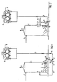
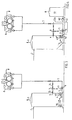
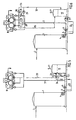
- Figs. 1-4 show different systems for degassing pulp suspensions.
- Figs. 5-6 show different systems for degassing liquor.
- a chest 1 is provided for a pulp suspension.
- the pulp is supplied to the chest through a feed line 2.
- a degassing valve 3 is located at the top of the chest 1 .
- the chest further comprises an agitator 4.
- An outlet line 5 for the pulp is connected to the lower portion of the chest 1.
- the pulp is pumped by a centrifugal pump 6 from the chest through the outlet line 5 and further through the pressure line 7 of the pump to subsequent processing stages, which in this case consist of a press 8 for dewatering and in combination with washing.
- An ejector 9 is coupled with its suction side 10 to the pump 6 via a suction line. 11.
- the ejector effect is obtained in known manner in that a drive medium passes through the ejector from an inlet 12 to an outlet 13.
- a branch line 14 is provided from the pressure line 7 to the inlet 12 of the ejector 9, and a return line 15 from the outlet 13 of the ejector back to the chest 1.
- the return line 15 is connected to the chest 1 directly in front of the outlet line 5 and agitator 4.
- Said agitator 4 is formed with a propeller 16, which effects a flow along the opposed wall,which is provided with an inclined portion 17. This implies, that the ejector 9 is driven by a partial flow of the medium, so that this partial flow via the suction line 11 sucks with it gas from the pump 6.
- the gas-enriched partial flow is returned to a portion of the chest 1 where the pulp flows upward due to the agitator effect.
- At the top of the chest a substantial part of the gas evacuates through the valve 3.
- the return line 15 from the ejector 9 is connected to the chest 1 above the outlet line 5 and agitator 4.
- the rotation direction of the propeller 16 of the agitator 4 is reverse, so that the upward flowing pulp flow in the chest passes past the connection of the return line 15.
- the line laying is more advantageous, because the ejector 9 is located directly above the pump 6 and agitator 4.
- the chest 1 is provided with an extra agitator 18, which can be necessary at large chests.
- the arrangement corresponds to the embodiment shown in Fig. 2.
- a container 19 for liquor is used for diluting the pulp.
- the liquor is pumped by a pump 40 through a line 22 to the chest 1 at the agitator 4 and to the outlet line 5.
- the ejector 9 is driven by a partial flow of liquor via a branch line 22a from the dilution liquor line 22.
- the arrangement corresponds to the embodiment shown in Fig. 2.
- a container 19 with liquor is used for diluting the pulp.
- the liquor arrives via a line 20 from the press 8 where the liquor is pressed out of the pulp.
- the liquor used for diluting the pulp is pumped ba a degassable centrifugal pump 21.
- Dilution liquor is there directed through a line 22 to the chest 1 at the agitator 4 and to the outlet line 5.
- an ejector 23 is driven by a partial flow of liquor via a branch line 24 from the dilution liquor line 22.
- Degassing of the liquor in the pump 21 takes place by the ejector via a suction line 25.
- a return line 26 for the partial liquor flow through the ejector is connected to the liquor container 19 above the maximum liquor level.
- the liquor container is at the top provided with a degassing valve 27.
- a glass gauge 28 for filtrate from the washing press 8 is located below the press.
- a degassable liquor pump 29 can there be connected to the glass gauge 28 with an accessory ejector 30 for degassing via a suction line 31.
- the liquor pump 29 pumps the liquor through a line 32 to the liquor container 19. This implies, that necessary filtrate flow from the press 8 can be obtained without any great difference in level.
- the ejector 30 is driven by a partial flow of the liquor via a branch line 33 from the line 32.
- a return line 34 for the partial flow through the ejector 30 is connected to a line 35 for degassing the glass gauge 28.
- This line 35 is connected to the liquor container 19 above the maximum liquor level. This arrangement further implies that the size of the liquor container 19 cen be reduced substantially.
Landscapes
- Engineering & Computer Science (AREA)
- Mechanical Engineering (AREA)
- General Engineering & Computer Science (AREA)
- Chemical Kinetics & Catalysis (AREA)
- Fluid Mechanics (AREA)
- Chemical & Material Sciences (AREA)
- Physics & Mathematics (AREA)
- Paper (AREA)
- Structures Of Non-Positive Displacement Pumps (AREA)
- Degasification And Air Bubble Elimination (AREA)
- Jet Pumps And Other Pumps (AREA)
- Diaphragms For Electromechanical Transducers (AREA)
- Addition Polymer Or Copolymer, Post-Treatments, Or Chemical Modifications (AREA)
- Macromolecular Compounds Obtained By Forming Nitrogen-Containing Linkages In General (AREA)
- Gas Separation By Absorption (AREA)
Claims (4)
- Verfahren zum Entgasen eines Gas enthaltenden fluiden Mediums, umfassend das Pumpen des Mediums aus einem Behälter (1, 19) durch eine Zentrifugalpumpe (6, 21, 29), die zur Gasabscheidung ausgelegt ist, wobei das Gas durch die Saugwirkung von einem Ejektor (9, 23, 30) evakuiert wird,
dadurch gekennzeichnet, dass ein Teilstrom des gepumpten Mediums in eine Abzweigleitung (14, 24, 33) nach der Pumpe (6, 21, 29) abgeleitet wird und als Antriebsquelle für den Ejektor (9, 23, 30) verwendet wird und dass der Teilstrom nach dem Ejektor in einer Rückleitung (15, 26, 34, 35) zu dem Behälter (1, 19) zurückgeleitet wird, von dem das Gas durch ein Entgasungsventil (3, 27) evakuiert wird. - Verfahren nach Anspruch 1,
dadurch gekennzeichnet, dass das Medium aus einer Flotte aus dem Pulpenherstellungsprozess besteht. - Vorrichtung zur Entgasung eines Gas enthaltenden fluiden Mediums, umfassend eine Zentrifugalpumpe (6, 21, 29) zum Pumpen des Mediums aus einem Behälter (1, 19), wobei die Pumpe zur Gasabscheidung ausgelegt ist, und einen Ejektor (9, 23, 30) zum Evakuieren des Gases aus der Pumpe,
dadurch gekennzeichnet, dass eine Abzweigleitung (14, 24, 33) von der Druckleitung (7, 22, 32) der Zentrifugalpumpe (6, 21, 29) an den Einlass des Ejektors (9, 23, 30) zum Antrieb des Ejektors mit einem Teilstrom des Mediums und eine Rückleitung (15, 26, 34, 35) für den Teilstrom von dem Auslass des Ejektors (9, 23, 30) an den Behälter (1, 19) angeschlossen ist, der mit einem Entgasungsventil (3, 27) versehen ist. - Vorrichtung nach Anspruch 3,
dadurch gekennzeichnet, dass die Zentrifugalpumpe (29) zum Pumpen von Flotte von einem Flüssigkeitsstandsglas (28) für Filtrat von einer Presse (8) zu einem Flottenbehälter (19) vorgesehen ist, und die Rückleitung (34, 35) von dem Ejektor (30) mit dem Flottenbehälter (19) verbunden ist.
Applications Claiming Priority (3)
| Application Number | Priority Date | Filing Date | Title |
|---|---|---|---|
| SE9601213 | 1996-03-27 | ||
| SE9601213A SE508348C2 (sv) | 1996-03-27 | 1996-03-27 | Sätt och anordning vid pumpning av ett gasinnehållande medium där gasen evakueras med hjälp av sugverkan från en ejektor |
| PCT/SE1997/000393 WO1997036044A1 (en) | 1996-03-27 | 1997-03-07 | Method and device at the pumping of a medium |
Publications (2)
| Publication Number | Publication Date |
|---|---|
| EP0889989A1 EP0889989A1 (de) | 1999-01-13 |
| EP0889989B1 true EP0889989B1 (de) | 2002-10-02 |
Family
ID=20402004
Family Applications (1)
| Application Number | Title | Priority Date | Filing Date |
|---|---|---|---|
| EP97919803A Revoked EP0889989B1 (de) | 1996-03-27 | 1997-03-07 | Verfahren und vorrichtung zum pumpen eines fluiden mediums |
Country Status (12)
| Country | Link |
|---|---|
| US (1) | US6139606A (de) |
| EP (1) | EP0889989B1 (de) |
| JP (1) | JP2000507324A (de) |
| CN (1) | CN1109158C (de) |
| AT (1) | ATE225431T1 (de) |
| AU (1) | AU2415197A (de) |
| BR (1) | BR9708266A (de) |
| CA (1) | CA2249248C (de) |
| DE (1) | DE69716049T2 (de) |
| ID (1) | ID16401A (de) |
| SE (1) | SE508348C2 (de) |
| WO (1) | WO1997036044A1 (de) |
Families Citing this family (7)
| Publication number | Priority date | Publication date | Assignee | Title |
|---|---|---|---|---|
| FR2783884B1 (fr) * | 1998-09-24 | 2000-10-27 | Inst Francais Du Petrole | Systeme de compression-pompage comportant une section de compression en fonctionnement alterne et son procede |
| CL2007002810A1 (es) * | 2006-11-07 | 2008-03-14 | Sulzer Pumpen Ag | Metodo y aparato para remover gas desde una suspension de liquido y solidos dentro de un contenedor que comprende una etapa adicional que consiste en reciclar al menos una porcion de una primera corriente de suspension dentro del contenedor hacia arr |
| US7947112B1 (en) | 2007-07-16 | 2011-05-24 | Rheodyne, Llc | Method for degassing a fluid |
| BR112013030212B1 (pt) * | 2011-05-24 | 2021-05-18 | Parker-Hannifin Corporation | dispositivo de desaeração e método de desaeração de fluido hidráulico |
| EP2891631B1 (de) * | 2014-01-03 | 2020-10-14 | Pharmtec SA | Dekontaminierungsverfahren und vorrichtung für abwasser |
| RU2715297C1 (ru) * | 2019-09-10 | 2020-02-26 | Акционерное общество "Новомет-Пермь" | Установка для поверхностной перекачки газожидкостной смеси |
| CN115434917B (zh) * | 2022-10-09 | 2023-06-16 | 三联泵业股份有限公司 | 一种用于输送多相流体的装置 |
Family Cites Families (14)
| Publication number | Priority date | Publication date | Assignee | Title |
|---|---|---|---|---|
| US3481113A (en) * | 1967-12-18 | 1969-12-02 | Gerald E Burnham Sr | Apparatus and method for the degassification of drilling muds |
| US3517487A (en) * | 1968-08-16 | 1970-06-30 | Gerald E Burnham Sr | Drilling mud flow and divider apparatus |
| US3616599A (en) * | 1970-02-19 | 1971-11-02 | Thermotics | Method and apparatus for the degasification of drilling muds |
| US3769779A (en) * | 1971-09-27 | 1973-11-06 | Smith International | Degassing apparatus |
| IT981244B (it) * | 1973-03-09 | 1974-10-10 | Brunato S | Degasificatore sottovuoto per fanghi di perforazione |
| US4097249A (en) * | 1976-12-27 | 1978-06-27 | Dresser Industries, Inc. | Method of fluid degassing |
| GB1591899A (en) * | 1976-12-27 | 1981-07-01 | Dresser Ind | Degasser spray vessel |
| US4097253A (en) * | 1976-12-27 | 1978-06-27 | Dresser Industries, Inc. | Mud degasser trough |
| US4410337A (en) * | 1980-04-07 | 1983-10-18 | A. Ahlstrom Osakeyhtio | Method and an apparatus for separating a gas from a fibre suspension |
| US4435193A (en) * | 1980-04-07 | 1984-03-06 | Kamyr Ab | Controlling operation of a centrifugal pump |
| US4516987A (en) * | 1983-07-21 | 1985-05-14 | Sundstrand Corporation | Deaerator usable in a system for a steam powered torpedo and deaerating method |
| DE3419305A1 (de) * | 1984-05-24 | 1985-11-28 | Spiro Research B.V., Helmond | Verfahren und vorrichtung zum vermindern des gasgehaltes einer fluessigkeit |
| CA1277543C (en) * | 1986-04-08 | 1990-12-11 | Lawrence E. Gazdik | Ejector for air evacuation in medium consistency pulp pumping |
| CH689004A5 (de) * | 1993-07-16 | 1998-07-15 | Staehle Martin | Kreiselpumpe. |
-
1996
- 1996-03-27 SE SE9601213A patent/SE508348C2/sv unknown
-
1997
- 1997-03-07 WO PCT/SE1997/000393 patent/WO1997036044A1/en not_active Ceased
- 1997-03-07 CN CN97193367A patent/CN1109158C/zh not_active Expired - Fee Related
- 1997-03-07 EP EP97919803A patent/EP0889989B1/de not_active Revoked
- 1997-03-07 CA CA002249248A patent/CA2249248C/en not_active Expired - Fee Related
- 1997-03-07 AT AT97919803T patent/ATE225431T1/de not_active IP Right Cessation
- 1997-03-07 AU AU24151/97A patent/AU2415197A/en not_active Abandoned
- 1997-03-07 US US09/155,120 patent/US6139606A/en not_active Expired - Fee Related
- 1997-03-07 JP JP9534304A patent/JP2000507324A/ja not_active Withdrawn
- 1997-03-07 DE DE69716049T patent/DE69716049T2/de not_active Expired - Fee Related
- 1997-03-07 BR BR9708266A patent/BR9708266A/pt not_active IP Right Cessation
- 1997-03-26 ID IDP970994A patent/ID16401A/id unknown
Also Published As
| Publication number | Publication date |
|---|---|
| JP2000507324A (ja) | 2000-06-13 |
| SE9601213L (sv) | 1997-09-28 |
| DE69716049D1 (de) | 2002-11-07 |
| CA2249248C (en) | 2004-05-25 |
| WO1997036044A1 (en) | 1997-10-02 |
| ID16401A (id) | 1997-09-25 |
| SE508348C2 (sv) | 1998-09-28 |
| US6139606A (en) | 2000-10-31 |
| SE9601213D0 (sv) | 1996-03-27 |
| ATE225431T1 (de) | 2002-10-15 |
| CN1214748A (zh) | 1999-04-21 |
| CN1109158C (zh) | 2003-05-21 |
| EP0889989A1 (de) | 1999-01-13 |
| BR9708266A (pt) | 1999-04-13 |
| CA2249248A1 (en) | 1997-10-02 |
| DE69716049T2 (de) | 2003-11-27 |
| AU2415197A (en) | 1997-10-17 |
Similar Documents
| Publication | Publication Date | Title |
|---|---|---|
| US4776758A (en) | Combined fluidizing and vacuum pump | |
| US5324166A (en) | Apparatus and method for pumping a liquid | |
| JPH02112495A (ja) | 空気またはガスを含む液体または繊維懸濁液の製造工程を改善する方法及び装置 | |
| FI95540C (fi) | Menetelmä ja laite kaasun erottamiseksi kiintoainetta sisältävästä nesteestä | |
| CA2249248C (en) | Method and device at the pumping of a medium | |
| US2745712A (en) | Process for countercurrent washing of cooking liquor out of pulp | |
| FI87049B (fi) | Anordning foer separering av gas ur en suspension innehaollande gas. | |
| EP0543866B1 (de) | Verfahren und vorrichtung zur stabilisierung und vereinfachung eines stoffverteilers für eine papiermaschine | |
| US5219472A (en) | Method of treating a fiber suspension | |
| US4378978A (en) | Degassing of liquid mixtures | |
| US6869504B2 (en) | Apparatus for passing stock into a headbox of a paper machine or equivalent | |
| JP3223340B2 (ja) | 液体の脱気方法 | |
| ES350529A1 (es) | Un metodo para eliminar en un proceso continuo componentes gaseosos y solidos a partir de suspensiones fibrosas liqui- das, en particular suspensiones fibrosas de pulpa celulosicay similares. | |
| WO2003093574A1 (en) | Process arrangement in the short circulation of a paper machine | |
| US5246633A (en) | Device for collecting used steam | |
| CN101918638A (zh) | 借助至少一个浮选设备从含水纸纤维悬浊液中去除杂质的方法 | |
| US6881028B2 (en) | Pumping device | |
| CA1161371A (en) | Degassing of liquid mixtures | |
| JPH07725A (ja) | 液体を除去する方法および装置 | |
| JPS5840317Y2 (ja) | 遠心ポンプに於ける流量変動防止機構 | |
| WO2001081675A1 (en) | A process and an apparatus for forming a web |
Legal Events
| Date | Code | Title | Description |
|---|---|---|---|
| PUAI | Public reference made under article 153(3) epc to a published international application that has entered the european phase |
Free format text: ORIGINAL CODE: 0009012 |
|
| 17P | Request for examination filed |
Effective date: 19980904 |
|
| AK | Designated contracting states |
Kind code of ref document: A1 Designated state(s): AT DE FI FR IT SE |
|
| RAP1 | Party data changed (applicant data changed or rights of an application transferred) |
Owner name: VALMET FIBERTECH AB |
|
| 17Q | First examination report despatched |
Effective date: 20010419 |
|
| GRAG | Despatch of communication of intention to grant |
Free format text: ORIGINAL CODE: EPIDOS AGRA |
|
| GRAG | Despatch of communication of intention to grant |
Free format text: ORIGINAL CODE: EPIDOS AGRA |
|
| GRAH | Despatch of communication of intention to grant a patent |
Free format text: ORIGINAL CODE: EPIDOS IGRA |
|
| GRAH | Despatch of communication of intention to grant a patent |
Free format text: ORIGINAL CODE: EPIDOS IGRA |
|
| GRAA | (expected) grant |
Free format text: ORIGINAL CODE: 0009210 |
|
| AK | Designated contracting states |
Kind code of ref document: B1 Designated state(s): AT DE FI FR IT SE |
|
| REF | Corresponds to: |
Ref document number: 225431 Country of ref document: AT Date of ref document: 20021015 Kind code of ref document: T |
|
| REF | Corresponds to: |
Ref document number: 69716049 Country of ref document: DE Date of ref document: 20021107 |
|
| ET | Fr: translation filed | ||
| PGFP | Annual fee paid to national office [announced via postgrant information from national office to epo] |
Ref country code: FR Payment date: 20030228 Year of fee payment: 7 |
|
| PLBI | Opposition filed |
Free format text: ORIGINAL CODE: 0009260 |
|
| PGFP | Annual fee paid to national office [announced via postgrant information from national office to epo] |
Ref country code: DE Payment date: 20030326 Year of fee payment: 7 |
|
| 26 | Opposition filed |
Opponent name: KVAERNER PULPING AB Effective date: 20030219 |
|
| PLAX | Notice of opposition and request to file observation + time limit sent |
Free format text: ORIGINAL CODE: EPIDOSNOBS2 |
|
| PLBB | Reply of patent proprietor to notice(s) of opposition received |
Free format text: ORIGINAL CODE: EPIDOSNOBS3 |
|
| PGFP | Annual fee paid to national office [announced via postgrant information from national office to epo] |
Ref country code: AT Payment date: 20040324 Year of fee payment: 8 |
|
| PG25 | Lapsed in a contracting state [announced via postgrant information from national office to epo] |
Ref country code: DE Free format text: LAPSE BECAUSE OF NON-PAYMENT OF DUE FEES Effective date: 20041001 |
|
| PG25 | Lapsed in a contracting state [announced via postgrant information from national office to epo] |
Ref country code: FR Free format text: LAPSE BECAUSE OF NON-PAYMENT OF DUE FEES Effective date: 20041130 |
|
| REG | Reference to a national code |
Ref country code: FR Ref legal event code: ST |
|
| PG25 | Lapsed in a contracting state [announced via postgrant information from national office to epo] |
Ref country code: IT Free format text: LAPSE BECAUSE OF NON-PAYMENT OF DUE FEES Effective date: 20050307 Ref country code: AT Free format text: LAPSE BECAUSE OF NON-PAYMENT OF DUE FEES Effective date: 20050307 |
|
| PGFP | Annual fee paid to national office [announced via postgrant information from national office to epo] |
Ref country code: FI Payment date: 20050317 Year of fee payment: 9 |
|
| PGFP | Annual fee paid to national office [announced via postgrant information from national office to epo] |
Ref country code: SE Payment date: 20050331 Year of fee payment: 9 |
|
| APBP | Date of receipt of notice of appeal recorded |
Free format text: ORIGINAL CODE: EPIDOSNNOA2O |
|
| APBM | Appeal reference recorded |
Free format text: ORIGINAL CODE: EPIDOSNREFNO |
|
| APBQ | Date of receipt of statement of grounds of appeal recorded |
Free format text: ORIGINAL CODE: EPIDOSNNOA3O |
|
| APAH | Appeal reference modified |
Free format text: ORIGINAL CODE: EPIDOSCREFNO |
|
| APBU | Appeal procedure closed |
Free format text: ORIGINAL CODE: EPIDOSNNOA9O |
|
| PG25 | Lapsed in a contracting state [announced via postgrant information from national office to epo] |
Ref country code: FI Free format text: LAPSE BECAUSE OF NON-PAYMENT OF DUE FEES Effective date: 20060307 |
|
| PG25 | Lapsed in a contracting state [announced via postgrant information from national office to epo] |
Ref country code: SE Free format text: LAPSE BECAUSE OF NON-PAYMENT OF DUE FEES Effective date: 20060308 |
|
| EUG | Se: european patent has lapsed | ||
| RDAF | Communication despatched that patent is revoked |
Free format text: ORIGINAL CODE: EPIDOSNREV1 |
|
| RDAG | Patent revoked |
Free format text: ORIGINAL CODE: 0009271 |
|
| STAA | Information on the status of an ep patent application or granted ep patent |
Free format text: STATUS: PATENT REVOKED |
|
| 27W | Patent revoked |
Effective date: 20141222 |
|
| REG | Reference to a national code |
Ref country code: SE Ref legal event code: ECNC |