EP0889618B1 - Anlage und Verfahren zur Kontrolle zugelassener Übertragungsgeschwindigkeit in einem Paketvermittlungsnetz - Google Patents
Anlage und Verfahren zur Kontrolle zugelassener Übertragungsgeschwindigkeit in einem Paketvermittlungsnetz Download PDFInfo
- Publication number
- EP0889618B1 EP0889618B1 EP19980112061 EP98112061A EP0889618B1 EP 0889618 B1 EP0889618 B1 EP 0889618B1 EP 19980112061 EP19980112061 EP 19980112061 EP 98112061 A EP98112061 A EP 98112061A EP 0889618 B1 EP0889618 B1 EP 0889618B1
- Authority
- EP
- European Patent Office
- Prior art keywords
- value
- transmitting terminal
- transmission
- rate
- packet
- Prior art date
- Legal status (The legal status is an assumption and is not a legal conclusion. Google has not performed a legal analysis and makes no representation as to the accuracy of the status listed.)
- Expired - Lifetime
Links
- 230000005540 biological transmission Effects 0.000 title claims description 146
- 238000000034 method Methods 0.000 title claims description 12
- 238000004422 calculation algorithm Methods 0.000 claims description 8
- 238000012544 monitoring process Methods 0.000 claims description 5
- 238000010276 construction Methods 0.000 description 12
- 230000003247 decreasing effect Effects 0.000 description 8
- 238000010586 diagram Methods 0.000 description 6
- 238000004364 calculation method Methods 0.000 description 5
- 230000003111 delayed effect Effects 0.000 description 5
- 230000007423 decrease Effects 0.000 description 4
- 230000006727 cell loss Effects 0.000 description 3
- 230000006870 function Effects 0.000 description 3
- 230000009172 bursting Effects 0.000 description 2
- 238000004891 communication Methods 0.000 description 2
- 238000007796 conventional method Methods 0.000 description 2
- 241000735495 Erica <angiosperm> Species 0.000 description 1
- 238000007792 addition Methods 0.000 description 1
- 238000001514 detection method Methods 0.000 description 1
- 230000000694 effects Effects 0.000 description 1
- 230000002045 lasting effect Effects 0.000 description 1
- 238000012546 transfer Methods 0.000 description 1
Images

Classifications
-
- H—ELECTRICITY
- H04—ELECTRIC COMMUNICATION TECHNIQUE
- H04L—TRANSMISSION OF DIGITAL INFORMATION, e.g. TELEGRAPHIC COMMUNICATION
- H04L12/00—Data switching networks
- H04L12/54—Store-and-forward switching systems
- H04L12/56—Packet switching systems
- H04L12/5601—Transfer mode dependent, e.g. ATM
- H04L12/5602—Bandwidth control in ATM Networks, e.g. leaky bucket
-
- H—ELECTRICITY
- H04—ELECTRIC COMMUNICATION TECHNIQUE
- H04Q—SELECTING
- H04Q11/00—Selecting arrangements for multiplex systems
- H04Q11/04—Selecting arrangements for multiplex systems for time-division multiplexing
- H04Q11/0428—Integrated services digital network, i.e. systems for transmission of different types of digitised signals, e.g. speech, data, telecentral, television signals
- H04Q11/0478—Provisions for broadband connections
-
- H—ELECTRICITY
- H04—ELECTRIC COMMUNICATION TECHNIQUE
- H04L—TRANSMISSION OF DIGITAL INFORMATION, e.g. TELEGRAPHIC COMMUNICATION
- H04L12/00—Data switching networks
- H04L12/54—Store-and-forward switching systems
- H04L12/56—Packet switching systems
- H04L12/5601—Transfer mode dependent, e.g. ATM
- H04L2012/5629—Admission control
- H04L2012/5631—Resource management and allocation
- H04L2012/5632—Bandwidth allocation
Definitions
- the present invention relates to a packet switching apparatus adapted to determine and control an allowed transmission rate to be informed to a transmitting terminal in a packet switching network in which a band management is done by feedback control, and a method of controlling the allowed transmission rate.
- ABR available bit rate
- ATM asynchronous transfer mode
- ABR service is disclosed in the document "ATM forum Traffic Management Specification Version 4.0 R11" (Shirish S. Sathaye, March 1996).
- ACR allowed cell rate
- RM resource management
- Fig. 4 is a schematic block diagram showing the configuration of an ATM network for an ABR service.
- the operation of the ABR service as in the document "ATM forum Traffic Management Specification Version 4.0 R11" will be described herebelow with reference to Fig. 4.
- an ATM network is generally indicated with a reference 401.
- the ATM network 401 incorporates an ATM switch 402 and has connected thereto a transmitting terminal 403 and receiving terminal 404.
- the transmitting terminal 403 mixes a forward resource management (FRM) cell in a data cell.
- FRM forward resource management
- BRM backward resource management
- the ATM cell 402 When the FRM cell sent from the transmitting terminal 403 and the BRM cell sent back from the receiving terminal 404 are passed through the ATM switch 402, the ATM cell 402 will write into either the FRM or BRM cell or into both an explicit rate (ER) indicative of how much congested the connections from the transmitting terminal 403 to the receiving terminal 404 are currently.
- the ER is a maximum transmission rate at which such connections routed through the ATM switch 402 are allowable without any congestion and which is currently allowed for the transmitting terminal 403.
- the connections through the ATM switch 402 are totally a low load, a higher ACR is allowable for the transmitting terminal 403. Therefore, the ER value calculated by the ATM switch 402 will be a large one.
- the ATM switch 402 will calculate a smaller ER value.
- the transmitting terminal 403 will increase or decrease the ACR based on an ER written in the BRM cell sent from the ATM switch 402 to effect a data communications at a rate within the range of increased or decreased ACR.
- the transmitting terminal 403 decreases the ACR because of a received ER value which is lower.
- the ACR is decreased due to an initialization thereof. More particularly, if a length of time for which the transmitting terminal 403 sends no FRM cell exceeds an ACR decrease time factor (ADTF), the ACR will be decreased to an initial cell rate (ICR). As described in the aforementioned document "ATM forum Traffic Management Specification Version 4.0 R11", this initialization is an operation effected by the transmitting terminal 403 controlling itself.
- One of the FRM cell sending conditions is that one FRM cell is sent for a predetermined number of data cells.
- the ACR initialization will be effected.
- the purpose of this ACR initialization is for the transmitting terminal 403 to resume with an ICR, not any ACR, a data transmission of which it has once been in pause, in a predetermined time from the pause, thereby preventing the network from being abruptly applied with a large load.
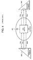
- Fig. 5 is a schematic block diagram of an ATM switch in the ATM network, showing the role of the ATM switch.
- transmitting terminals 502 equal in peak cell rate (PCR) to each other are connected to an ATM switch 504 to links 503, respectively, each having a linkage capacity which is same as the PCR of the transmitting terminals 501 and 502, they are multiplexed by an ATM switch 504, and connected to an ATM network 505 via another link 503.
- PCR peak cell rate
- one 501 will always send data at a full ACR as the actual transmission rate while the other 502 will send data initially at the full ACR, then at a rate extremely low (LCR) but at which the ACR is not initialized by the transmitting terminal itself, and at the full ACR again in a predetermined time after that.
- LCR rate extremely low
- Fig. 6 is a time chart showing the operations of the transmitting terminal 502 shown in Fig. 5.
- Fig. 6 shows values of an ER received by the transmitting terminal 502, and an ACR and an actual transmission rate, respectively, of the terminal 502.
- the actual transmission rate of the transmitting terminal 502 will be reduced to "LCR" at a time t0.
- the "LCR” is a very small value at which however the ACR will not be initialized.
- the ATM switch 504 will be applied with little load for the data transmission by the transmitting terminal 502. Therefore, the ATM 504 will calculate a new ER.
- the ER will be equal to "PCR” when calculated by the commonly used ER calculation method stated in "Explicit Rate Indication for Congestion Avoidance; ERICA)" in the aforementioned document "ATM forum Traffic Management Specification Version 4.0 R11".
- the ATM switch 504 will inform the new ER thus calculated thereby to the transmitting terminals 501 and 502.
- a propagation delay is caused by a distance between the transmitting terminal 502 and ATM switch 504.
- the transmitting terminal 501 has an actual transmission rate equal to "PCR” since the received new ER will lead to an ACR which takes a value "PCR".
- the actual transmission rate of the transmitting terminal 502 is very low being "LCR”, but the ACR will be maintained at “PCR” because the received ER has a value of "PCR".
- the transmitting terminals 501 and 502 will receive the ER of "PCR/2" and starts decreasing the ACR at a time t7 which is a predetermined time from the time t5 at which the congestion has first taken place. For a time period from the time t5 until t7, an extremely high possibility of cell loss will exist in the ATM switch 504.
- the conventional ATM network is disadvantageous in that if the actual transmission rate of a certain one of the transmitting terminals connected to the ATM network falls, the ACR has an higher ACR reflecting the reduced actual transmission rate, and if the transmitting terminal in question abruptly raises the actual transmission rate up to the full ACR, the ATM network will suddenly be applied with a large load so that a cell loss will take place with a result that the ATM network will incur a lower efficiency of data transmission.
- EP-A-0 548 995 describes a usage parameter control circuit for effecting a policing control in an ATM transmission network to restrict transmission of an arriving cell when the arriving cell is in violation of at least one of usage parameters declared by a subscriber (column 2, lines 20-26).
- This circuit comprises a time interval measuring unit (10) for measuring a time interval between a currently arrival time of a cell to be judged, and an arrival time of a cell which arrived a reference threshold number of cells before the currently arriving cell arrives; and a judging unit (20) for judging whether or not the measured time interval is shorter than a reference threshold time interval (T) (Abstract; Figure 2).
- the reference threshold number of cells and the reference threshold time interval are at least a part of the usage parameters declared by the subscriber and the currently arriving cell in the apparatus of [D1] being judged to be in violation of the usage parameters when the measured time interval is shorter than the predetermined time interval.
- the present invention has an object to overcome the above-mentioned drawbacks of the prior art by providing a packet switching apparatus destined for use in a packet transmission network and adapted to prevent the network from being suddenly applied with a high load without any rapid change of the actual transmission rate to a high value and avoid any cell loss even if the actual transmission rate of a certain one of transmitting terminals involved in an ABR service becomes lower and that transmitting terminal has a suddenly increased amount of data to send after the ACR of the transmitting terminal is initialized, and a method of controlling the transmission rate.
- the present invention has another object to provide a packet switching apparatus adapted to improve the safety of a network in which it is incorporated, by initializing the ACR of a transmitting terminal under control of the network, and a method of controlling the transmission rate.
- the present invention has a still another object to provide a packet switching apparatus adapted to judge the pause of transmission for each virtual path or virtual channel with no influence on the ACR of other virtual paths or virtual channels, and a method of controlling the transmission rate.
- the present invention have a yet another object to provide a packet switching apparatus in which a time of protection is set to judge whether a transmitting terminal is in pause of transmission to prevent the throughput from being reduced due to a frequent initialization of ACR, and a method of controlling the transmission rate.
- a packet switching apparatus adapted to determine and control an allowed transmission rate for a transmitting terminal connected in a packet switching network in which a band is controlled by a feedback control, comprises means for monitoring the interval of packet reception for each connection, and judging, based on the interval of packet reception, whether the transmitting terminal having sent the packet is in pause of transmission and determining a first allowed transmission rate for the transmitting terminal correspondingly to a result of the judgment, means for calculated a second allowed transmission rate based on a predetermined algorithm, and means for selecting a smaller one among the first allowed transmission rate determined by the rate discriminating means and the second allowed transmission rate calculated by the rate calculating means, and writing it into a packet returned to the transmitting terminal.
- the apparatus further comprises means for storing a threshold arbitrarily set for the interval of packet reception, the rate discriminating means judging, when the interval of packet reception is smaller than the threshold, the transmitting terminal having sent the packet to be in pause of transmission.
- the apparatus further comprises means for storing the arbitrarily set threshold for the interval of packet reception and an arbitrarily set protection time, the rate discriminating means judging, when the status in which the interval of packet reception is smaller than the threshold lasts for a time equivalent to the protection time, the transmitting terminal having sent the packet to be in pause of transmission.
- the rate discriminating means judges the transmitting terminal to be in pause of transmission, a preset value is taken for the first allowed transmission rate, when the transmitting terminal is not in pause of transmission, a maximum value allowed for a transmission in the network is taken for the first allowed transmission rate.
- the rate discriminating means judges the transmitting terminal to be in pause of transmission, a preset value which is approximately an initial transmission rate of the transmitting terminal is taken for the first allowed transmission rate, when the transmitting terminal is not in pause of transmission, a maximum value allowed for a transmission in the network is taken for the first allowed transmission rate.
- a packet switching apparatus adapted to determine and control an allowed transmission rate for a transmitting terminal connected in an ATM network being a packet switching network in which a band is controlled by a feedback control, and in which an ABR service is done in which a band control by a resource management cell is effected, comprises means for monitoring the interval of cell reception for each virtual path or channel of a reception cell, and judging, based on the interval of cell reception, whether the transmitting terminal having sent the cell is in pause of transmission and determining a first ER value for the transmitting terminal correspondingly to a result of the judgment, means for calculated a second ER value based on a predetermined algorithm, and means for selecting a smaller one among the first ER value determined by the rate discriminating means and the second ER value calculated by the rate calculating means, and writing it into a backward resource management cell returned to the transmitting terminal.
- the apparatus further comprises means for storing a threshold arbitrarily set for the interval of cell reception, the rate discriminating means judging, when the interval of cell reception is smaller than the threshold, the transmitting terminal having sent the cell to be in pause of transmission.
- the apparatus further comprises means for storing the arbitrarily set threshold for the interval of cell reception and an arbitrarily set protection time, the rate discriminating means judging, when the status in which the interval of cell reception is smaller than the threshold lasts for a time equivalent to the protection time, the transmitting terminal having sent the cell to be in pause of transmission.
- the rate discriminating means judges the transmitting terminal to be in pause of transmission, a preset value is taken for the first ER value, when the transmitting terminal is not in pause of transmission, a peak cell rate allowed for a transmission in the network is taken for the first ER value.
- the rate discriminating means judges the transmitting terminal to be in pause of transmission, a preset value which is approximately an initial cell rate of the transmitting terminal is taken for the first ER value, when the transmitting terminal is not in pause of transmission, a peak cell rate allowed for a transmission in the network is taken for the first ER value.
- a method of determining and controlling an allowed transmission rate for a transmitting terminal connected in a packet switching network in which a band is controlled by a feedback control comprising the steps of monitoring the interval of packet reception for each connection, judging, based on the interval of packet reception, whether the transmitting terminal having sent the packet is in pause of transmission and determining a first allowed transmission rate for the transmitting terminal correspondingly to a result of the judgment, calculating a second allowed transmission rate based on a predetermined algorithm, and selecting, a smaller one among the first allowed transmission rate and the second allowed transmission rate, and writing it into a packet returned to the transmitting terminal.
- the transmitting terminal having send the packet is judged to be in pause of transmission.
- the transmitting terminal having sent the packet is judged to be in pause of transmission.
- the step of determining the first allowed transmission rate further comprises the steps of taking a preset value for the first allowed transmission rate when the transmitting terminal is judged to be in pause of transmission, and taking, otherwise, for the first allowed transmission rate a maximum value allowed for a transmission in the network.
- the step of determining the first allowed transmission rate further comprises the steps of taking for the first allowed transmission rate a preset value which is approximately an initial transmission rate of the transmitting terminal when the transmitting terminal is judged to be in pause of transmission, and taking, otherwise, for the first allowed transmission rate a maximum value allowed for a transmission in the network.
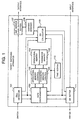
- Fig. 1 is a schematic block diagram showing the configuration of an embodiment of the packet switching apparatus according to the present invention.
- the packet switching apparatus according to this embodiment comprises a cell detector 101, a rate discriminator 102, an operational memory controller 103 and operational memory 104, a parameter memory controller 105 and parameter memory 106, an ABR service class output buffer 107, an address manager 108, an ER calculator 109, a timer keeper 110, and an ER setter 111.
- An ATM switch works in units of VP (virtual path) or in units of VC (virtual channel) as the case may be.
- the following description will refer to an ATM switch in which the packet switching apparatus according to the present invention is used works in units of VC (virtual channel).
- the embodiment of the present invention is applicable for an ATM switch which works in units of VP.
- the cell detector 101 receives a cell from a switch (not shown), sends a cell reception flag and VC value to the rate discriminator 102, and the cell reception flag, VC value and a cell class information to the ER calculator 109.
- the cell class information is an information indicating which the cell received from the switch is, a data cell or an RM cell.
- the rate discriminator 102 controls an arrival time of a cell for each VC.
- the operational memory controller 103 and operational memory 104 are used to calculate, based on a time at which a cell has been received, and keep in a same VC a time at which a next cell is to be received. Further, based on a time of cell interval thus calculated, a threshold rate (TCR) previously stored in the parameter memory 106 and a time of protection T TCR , an ER is determined and sent to the ER setter 111.
- TCR threshold rate
- TCR protection time TTCR
- the ER calculator 109 calculates an ER from the cell reception flag, VC value and cell class information received from the cell detector 101, and a queue length information received from the ABR service class output buffer 107 via the address manager 108.
- the ER calculation algorithm may be a conventional one.
- the time keeper 110 always counts a time and sends a current time to the rate discriminator 102 and ER calculator 109.
- the ER setter 111 Upon reception of a BRM cell from an input circuit interface (not shown), the ER setter 111 determines an ER value which is to be informed to a transmitting terminal on a VC to which the BRM belongs, writes it into the ER area of the BRM cell, and sends it to a switch (not shown).
- the ER value of the BRM cell is determined by selecting either of the ER values received from the rate discriminator 102 and ER calculator 109, whichever is smaller.
- the packet switching apparatus functions as will be discussed in detail with reference to Fig. 1:
- the cell detector 101 Upon arrival, through the switch, of a cell of a predetermined VC delivered from a predetermined transmitting terminal connected to the network, the cell detector 101 will send a flag indicating the reception of the cell and the value of the VC to the rate discriminator 102. Then the rate discriminator 102 will read a TCR and protection time T TCR from the parameter memory 106 by means of the parameter memory controller 105 to judge whether the transmitting terminal having sent the VC is substantially in pause of transmission. If the actual transmission rate of the received cell is lower than the TCR and the time for which the actual transmission rate lower than the TCR lasts reaches the protection time T TCR , the transmitting terminal is judged to be in pause of transmission.
- the actual transmission rate of the transmitting terminal is kept low for a certain length of time in some cases (the transmitting terminal is substantially in pause of transmission), while it is caused by a bursting traffic to temporarily be lower than the TCR in other cases. If it is assumed that the ACR is also initialized in case the rate is momentarily low, the initialization will be effected very frequently and the throughput become extremely low. To avoid this, a protection time T TCR is set for no ACR initialization to be done when a time period for which the actual transmission rate is lower than the TCR is shorter than the protection time T TCR . Since a TCR is set for initializing the ACR (a set value of TCR will be referred to as "TCR" herebelow), the TCR should desirably be same as the ICR of the transmitting terminal.
- the rate discriminator 102 When having judged the transmitting terminal not to be in pause of transmission, the rate discriminator 102 will set the ER value to be informed to the ER setter 111 to "PCR" of the transmitting terminal in consideration. This is intended for selecting, in selecting either an ER value determined by the rate discriminator 102 or a one calculated by the ER calculator 109, whichever is smaller, as an ER value of a BRM to be sent to the transmitting terminal in consideration, the ER value calculated by the ER calculator 109.
- the ER value to be sent to the ER setter 111 is set to "TCR".
- the ER calculator 109 Upon request from the ER setter 111, the ER calculator 109 will inform the ER setter 111 of a currently latest ER value.
- the ER calculator 109 calculates an ER from a VC value and cell class information received from the cell detector 101, a queue length information received from the address manager 108, and a time information received from the time keeper 110. Upon request from the ER setter 111, the ER calculator 109 will inform the ER setter 111 of a currently latest ER value.
- the ER setter 111 detects a BRM cell from among the cells received from an input circuit interface (not shown) and informs the rate discriminator 102 and ER calculator 109 of a VC of the detected BRM cell to request them for ER values for the VC. Upon reception of the ER values sent from the rate discriminator 102 and ER calculator 109, the ER setter 111 will compare the ER values with each other and selects a smaller one of them for writing into the BRM cell which will be sent to the switch (not shown).
- the ER value for sending to the transmitting terminal is normally a same one as in the prior art that indicates an ATM switch-allowable rate.
- the ER value will be changed over to a one intended for initialization of the ACR. If a congestion has caused the actual transmission rate to temporarily be lower, an ER value indicative of an ATM switch-allowable rate and smaller than the ER value intended for the ACR initialization, will be chosen.
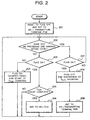
- the rate discriminator 102 in this embodiment functions as will be discussed in detail with reference to Fig. 2 being a flow chart of its operations.
- the rate discriminator 102 first resets a flag indicating that the rate of reception from the transmitting terminal is lower than TCR (the flag will be referred to as "status flag” hereinafter), and sets to PCR of the transmitting terminal an ER of which the ER setter 111 is to be informed (at step 201). Then, based on the cell reception flag and VC value received from the cell detector 101, the rate discriminator 102 will check whether after a cell of a predetermined VC value is received, a next cell of the same VC value is received within a time of "1/TCR" (at step 202).
- the transmitting terminal is judged not to be in pause of transmission. If the status flag is off, that is, if the transmission rate has already been higher than TCR before reception of the next cell, the operation returns to step 202 with no further operation (at step 207). On the other hand, if the status flag is on, it is turned off, the counting of the protection time T TCR is interrupted (at steps 207 and 208) and an ER value to be sent to the ER setter 111 is set to the PCR of the transmitting terminal on the VC in consideration (at step 209).
- the rate of reception from the transmitting terminal on the VC can be judged to be lower than "TCR".
- the status flag is off and the protection time T TCR is not yet counted, the status flag is turned on, the counter is reset, then the counting of the protection time T TCR is started (at steps 203 and 204), and it is judged again at step 202 whether the rate of cell reception is still lower than "TCR”.
- the rate of cell reception has already been less than "TCR" before the cell reception, namely, if the status flag is on (at step 203), it is judged whether the counting of the protection time T TCR is complete (at step 205).
- step 202 If the counting of the protection time T TCR is not yet complete, it is judged again at step 202 whether the rate of cell reception is lower than "TCR". If the counting of the protection time T TCR is complete, the rate of reception from the transmitting terminal on the VC becomes lower than "TCR” and the status has already lasted until the protection time T TCR , so that an ER value for sending to the ER setter 111 is set to "TCR" (at steps 205 and 206).
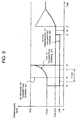
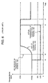
- Fig. 3 being a time chart of the operations of the transmitting terminal 502 in the network in Fig. 5 using the ATM switch in which the packet switching apparatus according to the present invention is incorporated.
- Fig. 3 shows values of ER, ACR and actual transmission rate received by the transmitting terminal 502.
- the transmitting terminals 502 equal in PCR to each other are connected to the ATM switch 504 to the links 503, respectively, each having a linkage capacity which is same as the PCR of the transmitting terminals 501 and 502, they are multiplexed by the ATM switch 504, and connected to the ATM network 505 by means of the single link 503.
- one 501 will always send data at a full ACR as the actual transmission rate while the other 502 will send data initially at the full ACR, then at a rate extremely low (LCR) but at which the ACR is not initialized by the transmitting terminal itself, and at the full ACR again in a predetermined time after that.
- LCR rate extremely low
- the ER value is "PCR/2" for no congestion of the ATM switch 504. Therefore, the ACR of the transmitting terminals 501 and 502 is also "PCR/2". Namely, the transmitting terminals 501 and 502 transmit data at the actual rate of "PCR/2".
- the actual transmission rate of the transmitting terminal 502 is reduced to "LCR" at a time t0. Since the distance between the transmitting terminal 502 and ATM switch 504 causes a propagation delay, the ATM switch 504 will receive the actual transmission rate "LCR" of the transmitting terminal 502 at the time t1 at which the ATM switch 504 will detect that the actual transmission rate is less than "TCR", and start counting the protection time T TCR .
- the ER value of which the transmitting terminal 502 is informed is a one calculated by the conventional ER calculator. Therefore, the load to the ATM switch 504 is halved because of the reduced actual transmission rate of the transmission terminal 502, so that the ER value increases up to "PCR". It is at a time t2 delayed a predetermined time caused by the propagation delay that the ER value arrives at the transmitting terminals 501 and 502.
- the ATM switch 504 will judge that the transmitting terminal 502 is substantially in pause of transmission and send an ER set to the value "TCR” to the transmitting terminal 502.
- the ER value sent to the transmitting terminal 501 remains as "PCR” with no change.
- an ER of the value "TCR” is received at a time t4 delayed a predetermined time from the time t3 because of the propagation delay, the value of ACR having increased toward "PCR” has to be decreased to "TCR” correspondingly to the received ER value.
- the ER value sent from the ATM switch 504 is not changed from “PCR” so long as the transmitting terminal 502 keeps transmitting data at a rate lower than "TCR".
- the actual transmission rate of the transmitting terminal 502 will be increased up to "TCR".
- the ATM switch 504 will detect the increased actual transmission rate, change the ER value from a one set to "TCR" to a one calculated by the conventional method of ER calculation, and send the ER value to the transmitting terminal 502.
- the transmitting terminal 502 will receive the new ER value, and increase the actual transmission rate little by little from "TCR” as the ACR value is increased.
- the present invention permits to prevent the actual transmission rate of the transmitting terminal from abruptly changing to a larger value.
- the present invention permits to effectively prevent a cell from being discarded when the network is suddenly applied with a large load.
- the present invention can assure a higher network safety than the prior art in which the increase or decrease of the actual data transmission rate is affected only by the operation of the transmitting terminal,
- ACR initialization is done by sending an ER value set nearly to ICR to a transmitting terminal judged to be in pause of transmission, any high ACR of the transmitting terminal will not be maintained. Therefore, even if the transmitting terminal has a suddenly increased amount of data to send, the actual transmission rate may be raised little by little.
Landscapes
- Engineering & Computer Science (AREA)
- Computer Networks & Wireless Communication (AREA)
- Signal Processing (AREA)
- Data Exchanges In Wide-Area Networks (AREA)
- Communication Control (AREA)
Claims (11)
- Paketvermittlungsvorrichtung, welche so ausgelegt ist, dass sie eine zulässige Übertragungsgeschwindigkeit für einen in einem Paketvermittlungsnetz angeschlossenen Sendeanschluss bestimmt und regelt, wobei in dem Paketvermittlungsnetz ein Band durch Closed-Loop Regelung geregelt wird, dadurch gekennzeichnet, dass die Vorrichtung Folgendes aufweist:eine Geschwindigkeits-Unterscheidungsvorrichtung (102) zum Überwachen des Zeitintervalls des Paketempfangs für jede Verbindung, und zum Beurteilen basierend auf dem Zeitintervall des Paketempfangs, ob der das Paket gesendete Sendeanschluss eine Übertragungspause macht, und zum Bestimmen eines ersten expliziten Geschwindigkeitswerts ER, bei dem es sich entsprechend einem Ergebnis der Beurteilung um eine für den Sendeanschluss zulässige maximale Übertragungsgeschwindigkeit handelt;eine Geschwindigkeits-Berechnungsvorrichtung (109) zum Berechnen eines zweiten ER-Werts basierend auf einem vorbestimmten Algorithmus; undeine Geschwindigkeits-Einstellvorrichtung (111) zum Wählen des kleineren ER-Werts aus dem von der Geschwindigkeits-Unterscheidungsvorrichtung (102) bestimmten ersten ER-Wert und dem von der Geschwindigkeits-Berechnungsvorrichtung (109) berechneten zweiten ER-Wert, und zum Schreiben des gewählten ER-Werts in ein Paket, das zurück an den Sendeanschluss gesendet wird.
- Vorrichtung nach Anspruch 1, welche weiter Folgendes aufweist:eine Vorrichtung (106) zum Speichern eines Schwellenwerts, der willkürlich für das Zeitintervall des Paketempfangs festgelegt wird;wobei die Geschwindigkeits-Unterscheidungsvorrichtung (102) beurteilt, wenn das Zeitintervall des Paketempfangs kleiner als ein vorbestimmter Schwellenwert ist, dass der Sendeanschluss, der das Paket gesendet hat, eine Übertragungspause macht.
- Vorrichtung nach Anspruch 1, welche weiter Folgendes aufweist:Vorrichtung (106) zum Speichern eines willkürlich für das Zeitintervall des Paketempfangs festgelegten Schwellenwerts und einer willkürlich festgelegten Schutzzeit;wobei die Geschwindigkeits-Unterscheidungsvorrichtung (102) beurteilt, dass, wenn der Zustand, in dem das Zeitintervall des Paketempfangs kleiner als der Schwellenwert ist, eine Zeit andauert, die identisch mit der Schutzzeit ist, der Sendeanschluss, der das Paket gesendet hat, eine Übertragungspause macht;
- Vorrichtung nach Anspruch 1, dadurch gekennzeichnet, dasswenn die Geschwindigkeits-Unterscheidungsvorrichtung (102) beurteilt, dass der Sendeanschluss eine Übertragungspause macht, ein im Voraus festgelegter Wert als erster ER-Wert genommen wird,wenn der Sendeanschluss keine Übertragungspause macht, ein für eine Übertragung im Netz zulässiger Maximalwert als erster ER-Wert genommen wird.
- Vorrichtung nach Anspruch 1, dadurch gekennzeichnet, dasswenn die Geschwindigkeits-Unterscheidungsvorrichtung (102) beurteilt, dass der Sendeanschluss eine Übertragungspause macht, ein im Voraus festgelegter Wert, der in etwa einer Anfangs-Übertragungsgeschwindigkeit des Sendeanschlusses entspricht, als erster ER-Wert genommen wird,wenn der Sendeanschluss keine Übertragungspause macht, ein für eine Übertragung im Netz zulässiger Maximalwert als erster ER-Wert genommen wird.
- Vorrichtung nach Anspruch 1, dadurch gekennzeichnet, dass das Paketvermittlungsnetz ein ATM-Netz (ATM = asynchrone Übermittlung) ist, in dem ein zur Verfügung stehender Bitgeschwindigkeits-Service ABR ausgeführt wird, in welchem eine Bandregelung mit Hilfe eines Betriebsmittel-Verwaltungspakets erfolgt, und dadurch gekennzeichnet, dassdie Geschwindigkeits-Unterscheidungsvorrichtung (102) so ausgelegt ist, dass sie das Zeitintervall eines Paketempfangs für jeden virtuellen Weg oder Kanal eines Empfangspakets überwacht, unddie Geschwindigkeits-Einstellvorrichtung (111) so ausgelegt ist, dass sie den gewählten ER-Wert in ein Rückwärts-Betriebsmittel-Verwaltungspaket schreibt, das zurück an den Sendeanschluss gesendet wird.
- Verfahren zur Bestimmung und Regelung einer zulässigen Übertragungsgeschwindigkeit für einen Sendeanschluss, der in einem Paketvermittlungsnetz angeschlossen ist, in dem ein Band durch Rückkopplung oder Regelung geregelt wird,
dadurch gekennzeichnet, dass das Verfahren folgende Schritte aufweist:Überwachung des Zeitintervalls des Paketempfangs für jede Verbindung;Beurteilung auf der Basis des Zeitintervalls des Paketempfangs, ob der Sendeanschluss, der das Paket gesendet hat, eine Übertragungspause macht, und Bestimmung eines ersten ER-Werts, bei dem es sich um eine maximal zulässige Übertragungsgeschwindigkeit für den Sendeanschluss entsprechend einem Ergebnis der Beurteilung handelt;Berechnen eines zweiten ER-Werts basierend auf einem vorbestimmten Algorithmus; undAuswählen des kleineren Werts aus dem ersten ER-Wert und dem zweiten ER-Wert, und Schreiben des ausgewählten ER-Werts in ein Paket, das dann zurück an den Sendeanschluss gesendet wird. - Verfahren nach Anspruch 7, dadurch gekennzeichnet, dassbeim Schritt der Bestimmung des ersten ER-Werts, wenn das Zeitintervall des Paketempfangs kleiner als ein vorbestimmter Schwellenwert ist, der das Paket gesendete Sendeanschluss so beurteilt wird, dass er eine Übertragungspause macht.
- Verfahren nach Anspruch 7, dadurch gekennzeichnet, dassbei dem Schritt der Bestimmung des ersten ER-Werts, wenn der Zustand, in dem das Zeitintervall des Paketempfangs kleiner als ein vorbestimmter Schwellenwert ist, eine Zeit andauert, die der Schutzzeit entspricht, der Sendeanschluss, der das Paket gesendet hat, so beurteilt wird, dass er eine Übertragungspause macht.
- Verfahren nach Anspruch 7, dadurch gekennzeichnet, dassder Schritt der Bestimmung des ersten ER-Werts weiter die folgenden Schritte aufweist:Annahme eines im Voraus festgelegten Werts als den ersten ER-Wert, wenn der Sendeanschluss so beurteilt wird, dass er eine Übertragungspause macht; undansonsten Annahme eines für eine Übertragung im Netz zulässigen Maximalwerts als den ersten ER-Wert.
- Verfahren nach Anspruch 7, dadurch gekennzeichnet, dassder Schritt der Bestimmung des ersten ER-Werts weiter die folgenden Schritte aufweist:Annahme eines im Voraus festgelegten Werts als den ersten ER-Wert, der in etwa einer anfänglichen Übertragungsgeschwindigkeit des Sendeanschlusses entspricht, wenn der Sendeanschluss so beurteilt wird, dass er eine Übertragungspause macht; undansonsten Annahme eines für eine Übertragung im Netz zulässigen Maximalwerts als ersten ER-Wert.
Applications Claiming Priority (3)
| Application Number | Priority Date | Filing Date | Title |
|---|---|---|---|
| JP17625097A JP3005501B2 (ja) | 1997-07-02 | 1997-07-02 | レート制御方式 |
| JP176250/97 | 1997-07-02 | ||
| JP17625097 | 1997-07-02 |
Publications (3)
| Publication Number | Publication Date |
|---|---|
| EP0889618A2 EP0889618A2 (de) | 1999-01-07 |
| EP0889618A3 EP0889618A3 (de) | 1999-07-28 |
| EP0889618B1 true EP0889618B1 (de) | 2005-06-29 |
Family
ID=16010288
Family Applications (1)
| Application Number | Title | Priority Date | Filing Date |
|---|---|---|---|
| EP19980112061 Expired - Lifetime EP0889618B1 (de) | 1997-07-02 | 1998-06-30 | Anlage und Verfahren zur Kontrolle zugelassener Übertragungsgeschwindigkeit in einem Paketvermittlungsnetz |
Country Status (5)
| Country | Link |
|---|---|
| US (1) | US6298042B1 (de) |
| EP (1) | EP0889618B1 (de) |
| JP (1) | JP3005501B2 (de) |
| CA (1) | CA2242216C (de) |
| DE (1) | DE69830688T2 (de) |
Families Citing this family (19)
| Publication number | Priority date | Publication date | Assignee | Title |
|---|---|---|---|---|
| JP3599557B2 (ja) * | 1998-02-27 | 2004-12-08 | 沖電気工業株式会社 | 処理レート監視装置 |
| US6633543B1 (en) * | 1998-08-27 | 2003-10-14 | Intel Corporation | Multicast flow control |
| US6400688B1 (en) * | 1998-09-23 | 2002-06-04 | Lucent Technologies Inc. | Method for consolidating backward resource management cells for ABR services in an ATM network |
| SE515837C2 (sv) * | 1999-01-22 | 2001-10-15 | Ericsson Telefon Ab L M | Adapterbar bandbredd |
| KR100364782B1 (ko) * | 2000-06-02 | 2002-12-16 | 엘지전자 주식회사 | 통신 시스템의 데이터 전송 방법 |
| DE60041059D1 (de) * | 2000-09-11 | 2009-01-22 | Lucent Technologies Inc | Verfahren und Vorrichtung um quellen spezifischen Datenfluss zu steuern |
| US20030031129A1 (en) * | 2001-06-12 | 2003-02-13 | Motorola, Inc. | Network packet flow admission control |
| JP3733943B2 (ja) * | 2002-10-16 | 2006-01-11 | 日本電気株式会社 | データ転送速度調停システム及びそれに用いるデータ転送速度調停方法 |
| US7664122B1 (en) | 2003-07-03 | 2010-02-16 | At&T Corp. | Call tracking using voice quality measurement probe |
| WO2005013033A2 (en) * | 2003-07-03 | 2005-02-10 | William Oakley | Array of cnt heads |
| WO2005067585A2 (en) * | 2003-07-03 | 2005-07-28 | William Oakley | Adaptive read and read-after-write for carbon nanotube recorders |
| US8019887B2 (en) * | 2003-09-04 | 2011-09-13 | Intel Corporation | Method, system, and program for managing a speed at which data is transmitted between network adaptors |
| US20050157646A1 (en) * | 2004-01-16 | 2005-07-21 | Nokia Corporation | System and method of network congestion control by UDP source throttling |
| JP2006094304A (ja) * | 2004-09-27 | 2006-04-06 | Nec Commun Syst Ltd | 伝送帯域制御方法及び伝送帯域制御システム |
| US7577097B2 (en) * | 2005-03-22 | 2009-08-18 | Microsoft Corporation | Compound transmission control protocol |
| KR101377841B1 (ko) * | 2007-01-17 | 2014-04-01 | 엘지전자 주식회사 | 네트워크 시스템의 통신 제어 방법 |
| JP4930148B2 (ja) * | 2007-03-29 | 2012-05-16 | ブラザー工業株式会社 | 情報処理装置、情報処理方法及び情報処理用プログラム |
| US20130159415A1 (en) * | 2010-06-07 | 2013-06-20 | Kansai University | Congestion control system, congestion control method, and communication unit |
| CN110531651B (zh) * | 2019-07-30 | 2022-07-29 | 中国人民解放军陆军工程大学 | 一种适用于以太网传输的速率控制装置 |
Family Cites Families (15)
| Publication number | Priority date | Publication date | Assignee | Title |
|---|---|---|---|---|
| EP0548995A2 (de) * | 1991-12-26 | 1993-06-30 | Fujitsu Limited | Steuerungsschaltung des Benutzungsparameters |
| GB2268372B (en) * | 1992-06-11 | 1995-11-01 | Roke Manor Research | Improvements in or relating to data transmission systems |
| JPH08204721A (ja) | 1995-01-27 | 1996-08-09 | Fujitsu Ltd | 非同期転送モード網における輻輳制御装置 |
| US5675576A (en) * | 1995-06-05 | 1997-10-07 | Lucent Technologies Inc. | Concestion control system and method for packet switched networks providing max-min fairness |
| JPH098814A (ja) | 1995-06-21 | 1997-01-10 | Fuji Xerox Co Ltd | データ伝送装置および伝送方法およびデータ通信システム |
| JP3087942B2 (ja) | 1995-09-18 | 2000-09-18 | 日本電信電話株式会社 | フロー制御装置 |
| JP2832591B2 (ja) | 1995-12-01 | 1998-12-09 | 株式会社超高速ネットワーク・コンピュータ技術研究所 | 一斉通知型輻輳制御方式 |
| JP3686493B2 (ja) * | 1996-03-07 | 2005-08-24 | 富士通株式会社 | Atm交換機におけるフィードバック制御方法および装置 |
| US5905711A (en) * | 1996-03-28 | 1999-05-18 | Lucent Technologies Inc. | Method and apparatus for controlling data transfer rates using marking threshold in asynchronous transfer mode networks |
| US5748901A (en) * | 1996-05-21 | 1998-05-05 | Ramot University Authority Ltd. | Flow control algorithm for high speed networks |
| US6038217A (en) * | 1996-06-27 | 2000-03-14 | Xerox Corporation | Rate shaping in per-flow output queued routing mechanisms for available bit rate (ABR) service in networks having segmented ABR control loops |
| US5805599A (en) * | 1996-12-04 | 1998-09-08 | At&T Corp. | Adaptive channel allocation system for communication network |
| JP3525656B2 (ja) | 1996-12-06 | 2004-05-10 | 株式会社日立製作所 | パケット交換機、および輻輳通知方式 |
| US5909443A (en) * | 1997-01-03 | 1999-06-01 | International Business Machines Corporation | ATM network congestion control system using explicit rate cell marking |
| US5987031A (en) * | 1997-05-22 | 1999-11-16 | Integrated Device Technology, Inc. | Method for fair dynamic scheduling of available bandwidth rate (ABR) service under asynchronous transfer mode (ATM) |
-
1997
- 1997-07-02 JP JP17625097A patent/JP3005501B2/ja not_active Expired - Fee Related
-
1998
- 1998-06-30 CA CA 2242216 patent/CA2242216C/en not_active Expired - Fee Related
- 1998-06-30 EP EP19980112061 patent/EP0889618B1/de not_active Expired - Lifetime
- 1998-06-30 DE DE1998630688 patent/DE69830688T2/de not_active Expired - Lifetime
- 1998-07-02 US US09/109,096 patent/US6298042B1/en not_active Expired - Lifetime
Also Published As
| Publication number | Publication date |
|---|---|
| JP3005501B2 (ja) | 2000-01-31 |
| CA2242216C (en) | 2002-12-10 |
| EP0889618A2 (de) | 1999-01-07 |
| DE69830688T2 (de) | 2006-04-27 |
| DE69830688D1 (de) | 2005-08-04 |
| US6298042B1 (en) | 2001-10-02 |
| JPH1127278A (ja) | 1999-01-29 |
| CA2242216A1 (en) | 1999-01-02 |
| EP0889618A3 (de) | 1999-07-28 |
Similar Documents
| Publication | Publication Date | Title |
|---|---|---|
| EP0889618B1 (de) | Anlage und Verfahren zur Kontrolle zugelassener Übertragungsgeschwindigkeit in einem Paketvermittlungsnetz | |
| EP0647081B1 (de) | Verfahren und Vorrichtung zur Überlastregelung in einem Kommunikationsnetzwerk | |
| EP0743803B1 (de) | Verfahren und System zur Regelung von Zellenübertragungsgeschwindigkeit in einem ATM-Netzwerk unter Verwendung einer Betriebsmittelverwaltungszelle | |
| US6259696B1 (en) | ATM switch and congestion control method | |
| EP0719012B1 (de) | Verkehrsverwaltung und Überlastregelung in einem paketbasierten Netz | |
| US6975630B1 (en) | System and method of avoiding cell disposal in buffer | |
| EP0688481B1 (de) | Vorrichtung und verfahren zur regulierung des zellflusses am ende eines atm systems | |
| EP0782302B1 (de) | Verfahren und Anlage zur Kontrolle von Übertragungsgeschwindigkeiten von Quellen in ATM-Netzwerken | |
| US7035211B1 (en) | Broadband switching network | |
| US6452905B1 (en) | Broadband switching system | |
| US6512743B1 (en) | Bandwidth allocation for ATM available bit rate service | |
| JPH05292114A (ja) | 通信パス設定装置及びその方法 | |
| US6388994B1 (en) | Traffic rate controller in a packet switching network | |
| JP3062041B2 (ja) | 非同期転送網における輻輳制御方式 | |
| JPH1023043A (ja) | データ流速度、待ち行列ネットワークノード、およびパケットスイッチングネットワークの制御方法 | |
| US6711133B1 (en) | Method for controlling congestion in ATM switching system | |
| JPH10224362A (ja) | セルレート制御装置 | |
| JP3079793B2 (ja) | 輻輳制御方法および呼受付制御方法 | |
| JP3835928B2 (ja) | コネクション受け付け制御装置 | |
| Kawahara et al. | Characteristics of ABR explicit rate control algorithms in WAN environment | |
| JP2757536B2 (ja) | 呼設定受付制御方法 | |
| Adams | A multiservice GFC protocol | |
| KR100299054B1 (ko) | 비동기전송모드 교환기에서 버퍼 관리를 이용한 가용 비트 속도 사용 파라미터 제어 방법 | |
| Zhang | A congestion control method for real-time applications in ATM networks | |
| JPH11243393A (ja) | 送信レート制御方法およびプログラム記録媒体 |
Legal Events
| Date | Code | Title | Description |
|---|---|---|---|
| PUAI | Public reference made under article 153(3) epc to a published international application that has entered the european phase |
Free format text: ORIGINAL CODE: 0009012 |
|
| AK | Designated contracting states |
Kind code of ref document: A2 Designated state(s): DE FR |
|
| AX | Request for extension of the european patent |
Free format text: AL;LT;LV;MK;RO;SI |
|
| PUAL | Search report despatched |
Free format text: ORIGINAL CODE: 0009013 |
|
| AK | Designated contracting states |
Kind code of ref document: A3 Designated state(s): AT BE CH CY DE DK ES FI FR GB GR IE IT LI LU MC NL PT SE |
|
| AX | Request for extension of the european patent |
Free format text: AL;LT;LV;MK;RO;SI |
|
| 17P | Request for examination filed |
Effective date: 19990618 |
|
| AKX | Designation fees paid |
Free format text: DE FR |
|
| 17Q | First examination report despatched |
Effective date: 20040527 |
|
| GRAP | Despatch of communication of intention to grant a patent |
Free format text: ORIGINAL CODE: EPIDOSNIGR1 |
|
| GRAS | Grant fee paid |
Free format text: ORIGINAL CODE: EPIDOSNIGR3 |
|
| GRAA | (expected) grant |
Free format text: ORIGINAL CODE: 0009210 |
|
| AK | Designated contracting states |
Kind code of ref document: B1 Designated state(s): DE FR |
|
| REF | Corresponds to: |
Ref document number: 69830688 Country of ref document: DE Date of ref document: 20050804 Kind code of ref document: P |
|
| ET | Fr: translation filed | ||
| PLBE | No opposition filed within time limit |
Free format text: ORIGINAL CODE: 0009261 |
|
| STAA | Information on the status of an ep patent application or granted ep patent |
Free format text: STATUS: NO OPPOSITION FILED WITHIN TIME LIMIT |
|
| 26N | No opposition filed |
Effective date: 20060330 |
|
| PGFP | Annual fee paid to national office [announced via postgrant information from national office to epo] |
Ref country code: FR Payment date: 20080617 Year of fee payment: 11 |
|
| REG | Reference to a national code |
Ref country code: FR Ref legal event code: ST Effective date: 20100226 |
|
| PG25 | Lapsed in a contracting state [announced via postgrant information from national office to epo] |
Ref country code: FR Free format text: LAPSE BECAUSE OF NON-PAYMENT OF DUE FEES Effective date: 20090630 |
|
| PGFP | Annual fee paid to national office [announced via postgrant information from national office to epo] |
Ref country code: DE Payment date: 20140625 Year of fee payment: 17 |
|
| REG | Reference to a national code |
Ref country code: DE Ref legal event code: R119 Ref document number: 69830688 Country of ref document: DE |
|
| PG25 | Lapsed in a contracting state [announced via postgrant information from national office to epo] |
Ref country code: DE Free format text: LAPSE BECAUSE OF NON-PAYMENT OF DUE FEES Effective date: 20160101 |