EP0889366B1 - Verfahren zur Erzeugung von Mikrostrukturen - Google Patents
Verfahren zur Erzeugung von Mikrostrukturen Download PDFInfo
- Publication number
- EP0889366B1 EP0889366B1 EP98111892A EP98111892A EP0889366B1 EP 0889366 B1 EP0889366 B1 EP 0889366B1 EP 98111892 A EP98111892 A EP 98111892A EP 98111892 A EP98111892 A EP 98111892A EP 0889366 B1 EP0889366 B1 EP 0889366B1
- Authority
- EP
- European Patent Office
- Prior art keywords
- inside surface
- coating
- photo
- cylinder liner
- microscopic
- Prior art date
- Legal status (The legal status is an assumption and is not a legal conclusion. Google has not performed a legal analysis and makes no representation as to the accuracy of the status listed.)
- Expired - Lifetime
Links
Images
Classifications
-
- G—PHYSICS
- G03—PHOTOGRAPHY; CINEMATOGRAPHY; ANALOGOUS TECHNIQUES USING WAVES OTHER THAN OPTICAL WAVES; ELECTROGRAPHY; HOLOGRAPHY
- G03F—PHOTOMECHANICAL PRODUCTION OF TEXTURED OR PATTERNED SURFACES, e.g. FOR PRINTING, FOR PROCESSING OF SEMICONDUCTOR DEVICES; MATERIALS THEREFOR; ORIGINALS THEREFOR; APPARATUS SPECIALLY ADAPTED THEREFOR
- G03F7/00—Photomechanical, e.g. photolithographic, production of textured or patterned surfaces, e.g. printing surfaces; Materials therefor, e.g. comprising photoresists; Apparatus specially adapted therefor
- G03F7/20—Exposure; Apparatus therefor
- G03F7/24—Curved surfaces
Definitions
- This invention relates to a method of providing the inside surface of a hollow object with at least one microscopic feature such as a valley or pit. More particularly but not exclusively the invention relates to a method of providing a microscopic feature for the retention of lubricant, in the inside surface of a cylinder lining in which a piston operates.
- Such features have been provided by a mechanical tool comprising a plurality of diamond or other cutting elements and the tool being rotated in the hollow of the liner to cut the features in the honed inside surface.
- diamond cutting tools are not expensive per boring operation, they usually require to be mounted on a machine head which is capable of movement about multiple axes, which is expensive.
- a method of providing the inside surface of a cylinder liner for an engine with at least one microscopic feature comprising the steps of coating at least a part of the inside surface with photo-sensitive material, directing light onto the material to photo-expose a selected portion of the material, removing the exposed selected portion or the unexposed material thereby to leave an opening through the coating, applying an etching substance to etch the inside surface through the opening to form a microscopic feature of a depth of between 3 ⁇ m & 15 ⁇ m in the inside surface, characterised in that the light which is directed onto the photo-sensitive material comprises a collimated beam and during exposure, the beam and the inside surface are relatively moved so that the beam impinges upon the selected portion of the photo-sensitive coating to be exposed.
- a method according to the invention it is possible to achieve consistently the provision of one or a pattern of microscopic features in the inside surface of a cylinder liner.
- an opening or openings may be provided in any desired position in the coating and to any desired pattern.
- the topography of the microscopic feature or features formed during etching can accurately be controlled. Because the microscopic features are written on to the photo-sensitive material directly by the light beam, there is no need to insert a mask in the hollow through which the photo-sensitive material needs to be exposed.
- the collimated beam is of laser light of a wavelength to which the photo-sensitive coating is sensitive, but unlike the prior art method described above which utilises a laser, the laser used to provide the light beam may be of low power.
- the low power laser light may itself remove selected portions of the photo-sensitive coating.
- the coating is chemically treated, e.g. by dipping the liner in a bath of the treating chemical, to remove the exposed portion of the coating or the unexposed coating, depending on the nature of the photo-sensitive coating.
- the photo-sensitive coating may be of the kind which is changed on exposure to light of a particular wavelength such that it may subsequently be chemically removed by developing, or the coating material may be of the kind which is changed on exposure to light of a particular wavelength such as to make it inert to a chemical which may be used to remove the unexposed photo-sensitive material.
- the beam of laser or other light may conveniently be manipulated, e.g. by means of one or more mirrors at least one of which may be located in the hollow, relative to the inside surface, and in tins way, the collimated beam may be directed to follow a predetermined path across the inside surface during exposure, thus to enable a predetermined pattern or patterns of openings to be provided through the photo-sensitive material, either when the exposed portions or unexposed material is removed, and hence so that a predetermined pattern or patterns of microscopic features may be provided in the inside surface during etching.
- the pattern of microscopic features may be varied over the inside surface so as to provide a greater density or different pattern of microscopic features over one region of the inside surface when compared with another region of the inside surface.
- a greater density or different design of microscopic features may be provided to enable greater lubrication at that position.
- the method of the invention may be performed in conjunction with a conventional honing technique whereby prior to coating the inside surface, the inside surface may be honed to a roughness of for example, less that 2 ⁇ m preferably of about 1 ⁇ m maximum peak to valley height.
- the coating of photo-sensitive material may be applied to the inside surface of the liner by any desired means. However most conveniently the inside surface is coated by dipping the liner in a bath of photo-sensitive material or by spraying.
- the etching substance may be applied by dipping the liner in a bath of etching substance from which the object is removed from after a predetermined time, and the etching substance may be removed or neutralised e.g. by washing after a predetermined period of time, so as to control the depth of the microscopic feature (or features) formed in the inside surface of the object.
- the etching substance may be applied by spraying the liner with etching substance for a predetermined time.
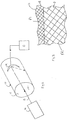
- a hollow object comprises a cylinder liner 10 which is generally cylindrical, and has a generally cylindrical inside surface 11.
- the method of the invention provides the inside surface 11 with at least one microscopic feature for retaining oil.
- examples of features P1 and P2 are indicated comprising a pattern of microscopic valleys or channels.
- the features P1 and P2 retain oil or other lubricant as a piston reciprocates in a hollow H of the cylinder liner 10.
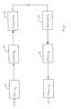
- the inside surface 11 of the liner 10 is honed at a honing station 12 using a conventional mechanical honing tool, which may have diamond cutting heads or the like.
- a conventional mechanical honing tool which may have diamond cutting heads or the like.
- the inside surface 11 is honed to a roughness preferably of about 1 ⁇ m to 2 ⁇ m maximum peak to valley height and thus the diamond or other abrasive particles used in the cutting head are themselves microscopic.
- the liner 10 is coated at a coating station 15 with photo-sensitive material.
- photo-sensitive material is a photo-resistive material comprising a solvent containing a suspension of polymeric particles, such as polyisoprene.
- commercially available such photo-resist material is sensitive to wavelengths of light within a generally narrow band of wavelengths and thus the material is preferably insensitive to ambient light in the manufacturing environment.
- the material is preferably a positive photo-resist which softens on exposure to light of the appropriate wavelength which facilitates removal of the exposed material during a subsequent chemical developing process.
- the coating is applied to a thickness of about 2 ⁇ m, but could be applied to a thickness of anywhere between 1 and 5 ⁇ m. Control of the thickness of the coating may be achieved by controlling the dwell time of the object 10 in the bath of the coating and/or the viscosity of the coating material.
- the cylinder liner 10 is positioned at an exposing station 16 where the coating is exposed to laser light in the wavelength to which the photo-sensitive material is sensitive.
- the direction of the beam B is manipulated by one or more mirrors M, at least one of which may be located within the hollow H of the liner 10. Movement of the minor M (or mirrors) may be controlled by a control means C (e.g. a computer control means) so that the beam B, where it impinges upon the coated inside surface 11 of the liner 10, is directed to follow a predetermined path across the inside surface 11 during exposure, thus to achieve a predetermined pattern or patterns of exposed portions of the photo-sensitive material.
- a control means C e.g. a computer control means
- the laser beam may be stationary and the component moved in a controlled manner so that the beam follows a predetermined path across the internal surface of the component.
- One suitable laser 14 is an ultra violet "HeCd" which produces a beam focused to between 5 and 8 ⁇ m diameter, although preferably a bigger beam, of between 15 and 25 ⁇ m is used, as it is desired to expose the photo-sensitive material to a width of between 20 and 40 ⁇ m. Essentially, lines are "written" into the photo-resistant material where it is desired to provide microscopic features P1, P2.
- the predetermined path of the beam B may comprise a single path which may cross over itself many times such that a single microscopic line is "written" into the photo-sensitive material.
- the beam B may not be continuous but may for example be intermittent, such that a plurality of individual microscopic features P1, P2 are provided.
- the mirror M may be mounted for example on a mobile arm and moved by means of one or more suitable actuators (not shown) under the control of the control means C.
- suitable actuators not shown
- relative movement between the beam B and the inside surface 11 of the liner 10 or other object may otherwise be achieved.
- the liner 10 may be rotated and/or traversed, so that the beam B impinges upon the inside surface 11 during exposure to enable one or more selected portions of the coating to be exposed.
- both the beam B and the object 10 could be moved if desired.
- the photo-sensitive coating is developed at a developing station 17.
- the softened photo-resist material is chemically removed to leave openings through the coating, corresponding to the positions where microscopic features P1, P2 are to be formed.
- the developer may be at an elevated temperature and the object 10 may be agitated in a bath of developer if necessary. Alternatively, the developer could be sprayed on.
- the object 10 may then be presented at an etching station 18 which may again be a bath, but of etching substance such as ferric chloride. It will be appreciated that during the developing stage 17, when the exposed portions of the coating are removed, the opening or openings in the coating will enable the etching substance to etch the inside surface 11 of the cylinder liner 10.
- the dwell time of the object 10 in the bath of etching substance may carefully be controlled so that the depth of the microscopic features P1, P2 formed, may carefully be controlled.
- the features are formed to a depth of between 3 and 15 ⁇ m.
- the etching effect may be stopped by removing the object 10 from the bath of etching substance and washing the object 10 e.g. by spraying water or a suitable neutralising chemical onto the object 10.
- the remaining photo-sensitive material is removed from the inside surface 11 of the cylinder liner 10, for example by using a higher power laser beam or more preferably, a solvent such as acetone, methylated spirit, or a concentrated hydroxide based developing solution.
- a solvent such as acetone, methylated spirit, or a concentrated hydroxide based developing solution.
- the chemical etching substance may be applied by spraying e.g. for a predetermined time.
- the pattern of microscopic features P1, P2 provided in the inside surface 11 of the object 10 may be determined by carefully controlling the predetermined path the laser or other beam B follows over the coating during the exposure process.
- region A is shown which is the so called "turn over" position i.e. the region of the cylinder liner 10 where the piston ring turns over as a piston operating in the cylinder liner 10 reverses its direction of reciprocation.
- this region A it is desirable for there to be greater lubrication and hence, by a method in accordance with the invention, a greater density of microscopic features P1 can conveniently be provided in that position.
- the most advantageous pattern or patterns of microscopic features for any particular application can be determined and by controlling the path of the laser or other light beam B during the exposure process, that pattern or patterns of microscopic features can be formed during the etching process.
- the photo-sensitive material is applied by dipping, and the material is developed by dipping, and the features are etched by dipping although in another arrangement, any of these materials/substances may be applied for example by spraying or by any other suitable means.
- the photo-sensitive material is a so called positive photo-resist which softens on exposure to a pre-determined wavelength of light.
- the coating may comprise a so called negative photo-resist material which hardens on exposure to light of a particularly pre-selected wavelength, such that during the developing or other chemical treating process 17, portions of the coating are removed which were unexposed during the exposure process 16.
- the laser or other light beam B would mark out on the coating on the inside surface 11 of the cylinder liner 10, not lines corresponding in position to the desired positions of the microscopic features, but the areas between the positions where it is desired to form microscopic features.
- ferric chloride has been described as a suitable etching substance, any other suitable etching substance, may instead be used.
- the invention has been described with reference to an object comprising a cylinder liner 10 in which the inside surface 11 is of cylindrical configuration, the invention is more generally applicable to providing one or more microscopic features in the inside surface 11 of any hollow object, but particularly, but not exclusively, a hollow object 10 made of metal, the inside surface 11 of which has been honed to a preselected roughness.
Landscapes
- Physics & Mathematics (AREA)
- General Physics & Mathematics (AREA)
- ing And Chemical Polishing (AREA)
- Pistons, Piston Rings, And Cylinders (AREA)
- Application Of Or Painting With Fluid Materials (AREA)
- Cylinder Crankcases Of Internal Combustion Engines (AREA)
- Exposure And Positioning Against Photoresist Photosensitive Materials (AREA)
Claims (13)
- Verfahren zum Versehen der Innenfläche (11) einer Zylinderlaufbuchse (10) eines Motors mit zumindest einer Mikrostruktur (P1, P2), umfassend die Schritte des Beschichtens von zumindest einem Teil der Innenfläche (11) mit einem lichtempfindlichen Material, des Richtens von Licht (B) auf das Material, um einen ausgewählten Bereich des Materials zu belichten, des Entfernens des belichteten Bereiches oder des nicht-belichteten Materials, wodurch eine Öffnung in der Beschichtung entsteht, des Aufbringens eines Ätzmiflels, um die Innenfläche (11) durch die Öffnung hindurch zu ätzen, um eine Mikrostruktur mit einer Tiefe von zwischen 3 µm und 15 µm in der Innenfläche (11) zu bilden,
dadurch gekennzeichnet, daß das Licht, welches auf das lichtempfindliche Material gerichtet wird, einen kollimierten Strahl (B) umfaßt und daß während der Belichtung der Strahl (B) und die Innenfläche (11) zueinander verschoben werden, so daß der Strahl (B) auf dem ausgewählten Bereich der zu belichtenden lichtempfindlichen Beschichtung auftrifft. - Verfahren nach Anspruch 1,
dadurch gekennzeichnet,
däß der kollimierte Strahl (B) aus Laserlicht einer Wellenlänge besteht, gegenüber welcher die lichtempfindliche Beschichtung empfindlich ist. - Verfahren nach Anspruch 1 oder Anspruch 2,
dadurch gekennzeichnet, daß die Beschichtung nach der Belichtung chemisch behandelt wird, um den belichteten Bereich der Beschichtung oder die nicht-belichtete Beschichtung zu entfernen. - Verfahren nach Anspruch 3,
dadurch gekennzeichnet, daß die Beschichtung chemisch behandelt wird, indem das Objekt in ein Bad der behandelnden Chemikalie eingetaucht oder die Zylinderlaufbuchse (10) mit der behandelnden Chemikalie besprüht wird. - Verfahren nach einem der vorhergehenden Ansprüche,
dadurch gekennzeichnet, daß der Strahl (B) während der Belichtung in Bezug auf die Innenfläche (11) so manipuliert wird, daß der kollimierte Strahl (B) geführt wird, um einem vorbestimmten Weg über die Innenfläche (11) während der Belichtung zu folgen. - Verfahren nach Anspruch 5,
dadurch gekennzeichnet, daß der Strahl (B) mit Hilfe eines oder mehrerer Spiegel (M) manipuliert wird, von denen zumindest einer im Hohlraum (H) der Zylinderlaufbuchse (10) vorgesehen ist. - Verfahren nach Anspruch 5 oder Anspruch 6,
dadurch gekennzeichnet, daß die Innenfläche (11) während der Belichtung mit einem vorbestimmten Muster von Mikrostrukturen versehen wird. - Verfahren nach Anspruch 7,
dadurch gekennzeichnet, daß das Muster von Mikrostrukturen (P1, P2) über die Innenfläche variiert wird, um eine größere Dichte und/oder unterschiedliche Muster von Mikrostrukturen (P1, P2) in einem Bezirk (A) der Innenfläche (11) im Vergleich zu einem anderen Bezirk (D) der Innenfläche (11) zu erzeugen. - Verfahren nach einem der vorhergehenden Ansprüche,
dadurch gekennzeichnet, daß vor der Beschichtung der Innenfläche (11) die Innenfläche (11) auf eine maximale Rauhtiefe von weniger als 2 µm gehont wird. - Verfahren nach einem der vorhergehenden Ansprüche,
dadurch gekennzeichnet, daß die Innenfläche (11) durch Eintauchen der Zylinderlaufbuchse (10) in ein Bad aus lichtempfindlichem Material beschichtet wird. - Verfahren nach einem der vorhergehenden Ansprüche,
dadurch gekennzeichnet, daß das Ätzmittel nach einer vorbestimmten Zeitspanne entfernt oder neutralisiert wird, um die Tiefe der in der Innenfläche (11) der Zylinderlaufbuchse (10) gebildeten Mikrostrukturen (P1, P2) zu kontrollieren. - Verfahren nach Anspruch 11,
dadurch gekennzeichnet, daß das Ätzmittel durch Eintauchen der Zylinderlaufbuchse (10) in ein Ätzmittelbad aufgebracht wird, aus dem das Objekt (10) nach einer vorbestimmten Zeit entfernt wird, wobei das Ätzmittel durch Abwaschen entfernt oder neutralisiert wird. - Verfahren nach Anspruch 11,
dadurch gekennzeichnet, daß das Ätzmittel durch Besprühen der Zylinderlaufbuchse (10) mit dem Ätzmittel für eine bestimmte Zeit aufgebracht wird.
Applications Claiming Priority (2)
| Application Number | Priority Date | Filing Date | Title |
|---|---|---|---|
| GB9714043A GB2326952B (en) | 1997-07-03 | 1997-07-03 | Method of providing microscopic features |
| GB9714043 | 1997-07-03 |
Publications (2)
| Publication Number | Publication Date |
|---|---|
| EP0889366A1 EP0889366A1 (de) | 1999-01-07 |
| EP0889366B1 true EP0889366B1 (de) | 2003-05-07 |
Family
ID=10815313
Family Applications (1)
| Application Number | Title | Priority Date | Filing Date |
|---|---|---|---|
| EP98111892A Expired - Lifetime EP0889366B1 (de) | 1997-07-03 | 1998-06-26 | Verfahren zur Erzeugung von Mikrostrukturen |
Country Status (5)
| Country | Link |
|---|---|
| US (1) | US6309806B1 (de) |
| EP (1) | EP0889366B1 (de) |
| JP (1) | JPH1171687A (de) |
| DE (1) | DE69814246T2 (de) |
| GB (1) | GB2326952B (de) |
Families Citing this family (12)
| Publication number | Priority date | Publication date | Assignee | Title |
|---|---|---|---|---|
| DE19956425A1 (de) * | 1999-11-24 | 2001-05-31 | Mahle Gmbh | Kolben für Verbrennungsmotoren |
| DE10302107A1 (de) * | 2003-01-21 | 2004-07-29 | Fuchs Technology Ag | Zylinderoberfläche |
| DE10339606B4 (de) * | 2003-08-28 | 2007-07-19 | Joachim Kieselbach | Vorrichtung zum Belichten der Innenwand einer Zylinderhülse zur Erzeugung von Rillenstrukturen auf zylindrischen Gleitflächen |
| US9307648B2 (en) | 2004-01-21 | 2016-04-05 | Microcontinuum, Inc. | Roll-to-roll patterning of transparent and metallic layers |
| US7833389B1 (en) | 2005-01-21 | 2010-11-16 | Microcontinuum, Inc. | Replication tools and related fabrication methods and apparatus |
| GB2410313B (en) * | 2004-01-22 | 2007-08-08 | Ford Global Tech Llc | An engine and a method of making same |
| EP1849181A4 (de) * | 2005-01-21 | 2009-03-18 | Microcontinuum Inc | Duplikationswerkzeuge und diesbezügliche herstellungsverfahren und -vorrichtungen |
| WO2013178246A1 (de) * | 2012-05-29 | 2013-12-05 | Hilti Aktiengesellschaft | Brennkraftbetriebenes setzgerät |
| KR101507107B1 (ko) * | 2012-07-17 | 2015-04-01 | (주)화백엔지니어링 | 곡면의 내주면 상에 미세 형상의 오일 포켓을 형성하는 장치 및 방법 |
| US9387567B2 (en) * | 2012-09-13 | 2016-07-12 | Electro-Motive Diesel, Inc. | Cylinder liner having three-tiered surface finish |
| US9589797B2 (en) | 2013-05-17 | 2017-03-07 | Microcontinuum, Inc. | Tools and methods for producing nanoantenna electronic devices |
| JP2015021185A (ja) * | 2013-07-16 | 2015-02-02 | 和百エンジニアリング株式会社 | 曲面状の内周面上に微細形状の凹部を形成する装置及びその方法 |
Family Cites Families (13)
| Publication number | Priority date | Publication date | Assignee | Title |
|---|---|---|---|---|
| US2968555A (en) | 1958-01-13 | 1961-01-17 | Gen Motors Corp | Treatment of metal surfaces |
| US3645178A (en) * | 1969-03-27 | 1972-02-29 | Ibm | Apparatus for exposing photoresist in cylinders |
| US3889696A (en) * | 1974-04-29 | 1975-06-17 | Allied Chem | Etching machine |
| US4049413A (en) | 1976-06-21 | 1977-09-20 | Bell Telephone Laboratories, Incorporated | Method for making optical fibers with variations in core diameter |
| JPS6047846A (ja) * | 1983-08-26 | 1985-03-15 | Mazda Motor Corp | エンジンのシリンダの製造方法 |
| DE3601319A1 (de) * | 1985-01-18 | 1986-07-24 | Mazda Motor Corp., Hiroshima | Verfahren zum ausbilden einer abriebfesten gleitflaeche |
| IL80241A (en) | 1986-10-07 | 1991-03-10 | Scitex Corp Ltd | Internal drum plotter |
| NL8802928A (nl) * | 1988-11-28 | 1990-06-18 | Stork Screens Bv | Werkwijze en inrichting voor het vormen van een weerstandspatroon op een cylindrisch voorwerp alsmede een onder toepassing van een dergelijk weerstandspatroon verkregen geetste metalen cylinder. |
| JP3239188B2 (ja) * | 1992-02-28 | 2001-12-17 | コニカ株式会社 | 光ビーム走査装置 |
| US5395718A (en) * | 1992-11-18 | 1995-03-07 | The Boeing Company | Conformal photolithographic method and mask for manufacturing parts with patterned curved surfaces |
| DE4316012C2 (de) * | 1993-05-13 | 1998-09-24 | Gehring Gmbh & Co Maschf | Verfahren zur Feinbearbeitung von Werkstück-Oberflächen |
| JPH0821297A (ja) * | 1994-06-30 | 1996-01-23 | Yamaha Motor Co Ltd | 内燃機関の摺接部構造 |
| GB9516771D0 (en) | 1995-08-16 | 1995-10-18 | Crosfield Electronics Ltd | Output scanner |
-
1997
- 1997-07-03 GB GB9714043A patent/GB2326952B/en not_active Expired - Fee Related
-
1998
- 1998-06-26 EP EP98111892A patent/EP0889366B1/de not_active Expired - Lifetime
- 1998-06-26 US US09/105,418 patent/US6309806B1/en not_active Expired - Fee Related
- 1998-06-26 DE DE69814246T patent/DE69814246T2/de not_active Expired - Fee Related
- 1998-07-03 JP JP10189000A patent/JPH1171687A/ja active Pending
Also Published As
| Publication number | Publication date |
|---|---|
| DE69814246T2 (de) | 2004-04-08 |
| DE69814246D1 (de) | 2003-06-12 |
| GB9714043D0 (en) | 1997-09-10 |
| GB2326952B (en) | 2002-06-12 |
| JPH1171687A (ja) | 1999-03-16 |
| EP0889366A1 (de) | 1999-01-07 |
| US6309806B1 (en) | 2001-10-30 |
| GB2326952A (en) | 1999-01-06 |
Similar Documents
| Publication | Publication Date | Title |
|---|---|---|
| US6309806B1 (en) | Method of providing microscopic features | |
| US5800285A (en) | Method of fabricating golf club parts carrying artwork etched after fabrication and parts with such artwork | |
| JP2683502B2 (ja) | 工作物の表面を精密加工するための方法 | |
| US6033721A (en) | Image-based three-axis positioner for laser direct write microchemical reaction | |
| US5853959A (en) | Method of fabricating a contoured slider surface feature with a single mask | |
| WO2001061870A3 (en) | Cylindrical processing of optical media | |
| EP0488402B1 (de) | Verfahren zum Schneiden von Rillen in ein hydrodynamisches Lager aus keramischem Werkstoff | |
| JP4058448B2 (ja) | レーザピーニング処理方法及びレーザ吸収粉体層シート | |
| JP2004510199A (ja) | 増加した涙流のための有孔レンズ及びそのレンズの製造方法 | |
| EP1004391B1 (de) | Verfahren und Vorrichtung zum Bearbeiten und Härten mittels Laser von Matrizenwalzen | |
| JPH02229687A (ja) | 物品の抵抗を減少する方法およびその方法によつて処理された物品 | |
| US6769962B2 (en) | Scraping method | |
| CN102666684A (zh) | 橡胶表面的加工方法及密封构件 | |
| EP1860499A2 (de) | Verfahren zum Herstellen einer Druckform | |
| JP4019533B2 (ja) | シリンダボア加工装置およびこれを用いた加工方法 | |
| KR102510082B1 (ko) | 레이저 커팅 방법 | |
| EP0631837A1 (de) | Herstellung einer Prägewalze | |
| US5200593A (en) | Method of controlling the length of metal chips | |
| JPS6171133A (ja) | マスタ−シリンダ補償孔パンチ加工方法及び装置 | |
| Piccolo et al. | Surface Micro-/Nano-Texturing of Plastics Manufacturing Tools | |
| JPS62218587A (ja) | レ−ザを利用した選択的エツチング方法 | |
| KR102510081B1 (ko) | 레이저 커팅 장치 | |
| RU2142874C1 (ru) | Способ шлифования отверстия в цилиндрической детали | |
| JP2003205380A (ja) | 摺動面加工方法及び摺動装置 | |
| KR20010022516A (ko) | 웨이퍼 마킹 방법 |
Legal Events
| Date | Code | Title | Description |
|---|---|---|---|
| PUAI | Public reference made under article 153(3) epc to a published international application that has entered the european phase |
Free format text: ORIGINAL CODE: 0009012 |
|
| AK | Designated contracting states |
Kind code of ref document: A1 Designated state(s): DE ES FR GB IT NL SE |
|
| AX | Request for extension of the european patent |
Free format text: AL;LT;LV;MK;RO;SI |
|
| 17P | Request for examination filed |
Effective date: 19990705 |
|
| AKX | Designation fees paid |
Free format text: DE ES FR GB IT NL SE |
|
| 17Q | First examination report despatched |
Effective date: 20001130 |
|
| GRAH | Despatch of communication of intention to grant a patent |
Free format text: ORIGINAL CODE: EPIDOS IGRA |
|
| RIC1 | Information provided on ipc code assigned before grant |
Free format text: 7G 03F 7/24 A, 7F 16J 10/04 B |
|
| RIC1 | Information provided on ipc code assigned before grant |
Free format text: 7G 03F 7/24 A, 7F 16J 10/04 B |
|
| GRAH | Despatch of communication of intention to grant a patent |
Free format text: ORIGINAL CODE: EPIDOS IGRA |
|
| GRAA | (expected) grant |
Free format text: ORIGINAL CODE: 0009210 |
|
| RBV | Designated contracting states (corrected) |
Designated state(s): DE ES FR IT NL SE |
|
| AK | Designated contracting states |
Designated state(s): DE ES FR IT NL SE |
|
| PG25 | Lapsed in a contracting state [announced via postgrant information from national office to epo] |
Ref country code: NL Free format text: LAPSE BECAUSE OF FAILURE TO SUBMIT A TRANSLATION OF THE DESCRIPTION OR TO PAY THE FEE WITHIN THE PRESCRIBED TIME-LIMIT Effective date: 20030507 Ref country code: IT Free format text: LAPSE BECAUSE OF FAILURE TO SUBMIT A TRANSLATION OF THE DESCRIPTION OR TO PAY THE FEE WITHIN THE PRESCRIBED TIME-LIMIT;WARNING: LAPSES OF ITALIAN PATENTS WITH EFFECTIVE DATE BEFORE 2007 MAY HAVE OCCURRED AT ANY TIME BEFORE 2007. THE CORRECT EFFECTIVE DATE MAY BE DIFFERENT FROM THE ONE RECORDED. Effective date: 20030507 |
|
| REF | Corresponds to: |
Ref document number: 69814246 Country of ref document: DE Date of ref document: 20030612 Kind code of ref document: P |
|
| PGFP | Annual fee paid to national office [announced via postgrant information from national office to epo] |
Ref country code: ES Payment date: 20030619 Year of fee payment: 6 |
|
| PG25 | Lapsed in a contracting state [announced via postgrant information from national office to epo] |
Ref country code: SE Free format text: LAPSE BECAUSE OF FAILURE TO SUBMIT A TRANSLATION OF THE DESCRIPTION OR TO PAY THE FEE WITHIN THE PRESCRIBED TIME-LIMIT Effective date: 20030807 |
|
| PG25 | Lapsed in a contracting state [announced via postgrant information from national office to epo] |
Ref country code: ES Free format text: LAPSE BECAUSE OF FAILURE TO SUBMIT A TRANSLATION OF THE DESCRIPTION OR TO PAY THE FEE WITHIN THE PRESCRIBED TIME-LIMIT Effective date: 20030818 |
|
| NLV1 | Nl: lapsed or annulled due to failure to fulfill the requirements of art. 29p and 29m of the patents act | ||
| PLBE | No opposition filed within time limit |
Free format text: ORIGINAL CODE: 0009261 |
|
| STAA | Information on the status of an ep patent application or granted ep patent |
Free format text: STATUS: NO OPPOSITION FILED WITHIN TIME LIMIT |
|
| ET | Fr: translation filed | ||
| 26N | No opposition filed |
Effective date: 20040210 |
|
| PGFP | Annual fee paid to national office [announced via postgrant information from national office to epo] |
Ref country code: FR Payment date: 20060608 Year of fee payment: 9 |
|
| PGFP | Annual fee paid to national office [announced via postgrant information from national office to epo] |
Ref country code: DE Payment date: 20060622 Year of fee payment: 9 |
|
| REG | Reference to a national code |
Ref country code: FR Ref legal event code: ST Effective date: 20080229 |
|
| PG25 | Lapsed in a contracting state [announced via postgrant information from national office to epo] |
Ref country code: DE Free format text: LAPSE BECAUSE OF NON-PAYMENT OF DUE FEES Effective date: 20080101 |
|
| PG25 | Lapsed in a contracting state [announced via postgrant information from national office to epo] |
Ref country code: FR Free format text: LAPSE BECAUSE OF NON-PAYMENT OF DUE FEES Effective date: 20070702 |