EP0889138B1 - Verfahren und Vorrichtung zur Erzeugung von hochchromhaltigen Stählen und/oder Ferrolegierungen in einem Elektro-Lichtbogen-Konverter - Google Patents
Verfahren und Vorrichtung zur Erzeugung von hochchromhaltigen Stählen und/oder Ferrolegierungen in einem Elektro-Lichtbogen-Konverter Download PDFInfo
- Publication number
- EP0889138B1 EP0889138B1 EP98111571A EP98111571A EP0889138B1 EP 0889138 B1 EP0889138 B1 EP 0889138B1 EP 98111571 A EP98111571 A EP 98111571A EP 98111571 A EP98111571 A EP 98111571A EP 0889138 B1 EP0889138 B1 EP 0889138B1
- Authority
- EP
- European Patent Office
- Prior art keywords
- vessel
- melt
- converter
- reduced
- nozzles
- Prior art date
- Legal status (The legal status is an assumption and is not a legal conclusion. Google has not performed a legal analysis and makes no representation as to the accuracy of the status listed.)
- Expired - Lifetime
Links
Images



Classifications
-
- C—CHEMISTRY; METALLURGY
- C21—METALLURGY OF IRON
- C21C—PROCESSING OF PIG-IRON, e.g. REFINING, MANUFACTURE OF WROUGHT-IRON OR STEEL; TREATMENT IN MOLTEN STATE OF FERROUS ALLOYS
- C21C7/00—Treating molten ferrous alloys, e.g. steel, not covered by groups C21C1/00 - C21C5/00
- C21C7/04—Removing impurities by adding a treating agent
- C21C7/068—Decarburising
- C21C7/0685—Decarburising of stainless steel
-
- C—CHEMISTRY; METALLURGY
- C21—METALLURGY OF IRON
- C21C—PROCESSING OF PIG-IRON, e.g. REFINING, MANUFACTURE OF WROUGHT-IRON OR STEEL; TREATMENT IN MOLTEN STATE OF FERROUS ALLOYS
- C21C5/00—Manufacture of carbon-steel, e.g. plain mild steel, medium carbon steel or cast steel or stainless steel
- C21C5/005—Manufacture of stainless steel
-
- C—CHEMISTRY; METALLURGY
- C21—METALLURGY OF IRON
- C21C—PROCESSING OF PIG-IRON, e.g. REFINING, MANUFACTURE OF WROUGHT-IRON OR STEEL; TREATMENT IN MOLTEN STATE OF FERROUS ALLOYS
- C21C5/00—Manufacture of carbon-steel, e.g. plain mild steel, medium carbon steel or cast steel or stainless steel
- C21C5/52—Manufacture of steel in electric furnaces
- C21C5/5264—Manufacture of alloyed steels including ferro-alloys
-
- Y—GENERAL TAGGING OF NEW TECHNOLOGICAL DEVELOPMENTS; GENERAL TAGGING OF CROSS-SECTIONAL TECHNOLOGIES SPANNING OVER SEVERAL SECTIONS OF THE IPC; TECHNICAL SUBJECTS COVERED BY FORMER USPC CROSS-REFERENCE ART COLLECTIONS [XRACs] AND DIGESTS
- Y02—TECHNOLOGIES OR APPLICATIONS FOR MITIGATION OR ADAPTATION AGAINST CLIMATE CHANGE
- Y02P—CLIMATE CHANGE MITIGATION TECHNOLOGIES IN THE PRODUCTION OR PROCESSING OF GOODS
- Y02P10/00—Technologies related to metal processing
- Y02P10/20—Recycling
Definitions
- the invention relates to a method and device for the production of steels with predominantly high Cr content and / or ferro alloys, the metallic insert melted in a melting vessel, alloyed, freshened and reduced, and where Process gases are simultaneously fed through floor nozzles become.
- the best known is the melting in the arc furnace or melting in the arc furnace with downstream freshening up in a converter Use of mixed gases or under vacuum.
- Stainless steels preferably with high Cr and Ni levels have changed from the system design the so-called “duplex method” - use of a Electric arc furnace with downstream converter - and the so-called “triplex process” - use of an arc furnace with a downstream converter and downstream vacuum system - enforced.
- the arc furnace is used in both system designs each as a pre-melting unit.
- the actual Fine-tuning process to produce the desired steel quality with high alloy proportions and low Carbon contents are also in a converter lateral under bath jets, in a converter with Floor nozzles or in a converter with both Nozzle arrangements, - on the side and in the bottom -.
- the AOD (argon, oxygen, decarburization) and the improved AOD (argon, oxygen, decarburization) (lance) method with a converter with a specific volume of 0.45-0.60 m 3 / are known. t steel.
- the original procedure works with only one or multiple floor jets while the improved process via a lance through the vessel opening blowing oxygen in at the top.
- the CLU- (L) is also known (Creusot Loire Uddeholm) process in which a Part of the inert gas to reduce the CO partial pressure is replaced by superheated steam.
- a converter with a specific reaction space between 0.45 and 0.8 Nm 3 / t steel is used and the process gas supply during the converter treatment is regulated in the range from 0.5 to 2.0 Nm 3 / t ⁇ min.
- the process gas is supplied in the converter through injection openings in the ground or near the ground, while during the converter mouth temporarily during the deoxidation phase is reduced and during the tapping on the steel a slag containing a deoxidizing substance is abandoned.
- DE 195 09 285 C1 is a melting vessel system with one or two arranged side by side Converter vessels known, the melting vessel with by circumferentially arranged support elements on the inside Race rings is releasably attached and where each of the inner races using roller segments in one outer race, which is in a track groove on running rails rolls, is stored.
- EP 0 630 977 A1 describes a converter for Manufacture of steel from solid and / or liquid Feedstocks such as pig iron and / or scrap and / or Sponge iron is known to be a fireproof lined Fresh vessel, an oxygen or an oxygen-containing one Gas supplying fresh device and a heating device having.
- the heating device points to the production of the steel at least one self-consuming graphite electrode and the freshening device is independent of the heating device either from an oxygen blowing lance formed or points below the melt pool level horizontal oxygen-blowing floor and / or side jets on.
- the method is characterized in that in one the first step is a major fresh ironing and optionally a subset of scrap and / or Sponge iron is carried out and then in a second step additionally introduced Scrap and / or sponge iron melted and if necessary simultaneously or in a third process step is freshened, the first process step only the freshener is active and in further process steps, both the freshening device as well as at least one graphite electrode are activated, in the case of inflation of Alternating oxygen and in case of blowing in Oxygen from below the melt pool level alternating or simultaneously.
- the object of the invention is a steelmaking process and a corresponding device to create the temperature - or energy - as well Output or metal losses, especially the Chromium losses in the production of stainless steels further reduced, which lowers plant and operating costs and the economy of manufacturing high and highest alloyed stainless steels, especially of RHS qualities improved overall.
- the task is solved in the manner in which Claim 1 and claim 8 is specified.
- the requirements 2 - 7 relate to an advantageous implementation of the Method, claims 9-12 an advantageous Design of the device.
- a melting unit is created the characteristics of an electric arc furnace and of a converter combined, whereby when used of solid metallic feedstocks in the form of commercial stainless steel scrap and alloying agents the energy to melt and make one Premelt over the electrical energy of the Arc occurs.
- reaction, cooling and inert gases are supplied via nozzles installed in the bottom of the converter or laterally above the bottom, the specific blowing rates in a range from 0.1 to 3.0 Nm 3 / t steel lie.
- O 2 , CO 2 , N 2 , Ar are used as process gases, and CH 2 , N 2 , Ar, air as cooling gases.
- the melting pot for performing the process is with a bulbous bearing rotatably mounted in a support ring Vessel middle and lower part equipped and with provided with an interchangeable floor, in the floor nozzles are arranged.
- the vessel can be swung out Top part or vessel lid are covered, whereby the vessel opening is kept as small as possible in order to Penetration of false air during the process Prevent vessel.
- the support ring is semicircular, and the vessel side opposite the support ring in the upper Part is designed as a vertical vessel wall.
- Electrodes inserted into the melting vessel.
- the in Bottom arranged nozzles are known as Annular gap or jacket nozzles formed. Furthermore, in bulbous middle part of a tap is arranged his.
- the melting vessel according to the invention result in the system design compared to the Duplex processes a number of savings. So can used a single-aisle hall, for example a ladle transport vehicle that is between two Halls wrong, the required ones can be omitted Crane systems, bunker systems with dosing and Feeding devices for alloying agents and Aggregates that become dedusting plants reduced.
- the consumption values can Tap-to-tap time reduced compared to the duplex method become.
- the ff consumption can in the inventive system in be significantly reduced.
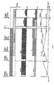
- Fig. 1 shows the schematic course of treatment of a 100 t melt in the converter vessel according to the invention, the feed of electrical energy from a 95 MVA transformer.
- the final carbon content of 0.3% is calculated reached after 61.0 minutes. After that, the melt is in emptied a ladle and for further treatment transported in a vacuum system. In the vacuum system we you. a. a decarbon content of 0.005% reached.
- Fig. 2 shows the schematic course of treatment of a 100 t melt in the converter vessel according to the invention, the feed of electrical energy from a 95 MVA transformer.
- a carbon content of 0.3% is calculated here reached after 56.0 minutes. Through another treatment time of approx. The target is 20 minutes C content of 0.02 - 0.05% reached.
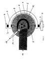
- FIG 3 shows a top view of the melting vessel (1), that in a semicircular support ring (2) in pivot bearings (4) with one-sided drive (3).
- the vessel (1) is in a curved vessel part (5) and a cylindrical vessel part (6) divided, whereby from Construction and symmetry reasons the transition in Area of the axis of rotation (7) is arranged.
- the electrodes (8) are through the upper part of the vessel (12) lowered into the vessel (1), the flue gases are suctioned off via a suction hood (11) and one dedusting system, not shown.
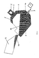
- Fig. 4 shows a side view of the in a support ring (2) stored converter vessel (1) in charging position, whereby solid, metallic feedstocks (14) with a charging trough (13) on the cylindrical vessel part (6) be charged into the converter vessel (1).
- the Charging is air or nitrogen through the blown in the floor (10) arranged floor nozzles (9).
- the flue gases are extracted through a suction hood (11).
- alloys or additives (18) are added via a feed (17), the treatment of the melt is carried out to a reduced extent by electrical energy via the electrodes (8) and by the reaction gases - O 2 / CO 2 , N 2 , Ar - via the floor nozzles (9) arranged in the floor (10).
Landscapes
- Chemical & Material Sciences (AREA)
- Engineering & Computer Science (AREA)
- Materials Engineering (AREA)
- Metallurgy (AREA)
- Organic Chemistry (AREA)
- Manufacturing & Machinery (AREA)
- Treatment Of Steel In Its Molten State (AREA)
- Refinement Of Pig-Iron, Manufacture Of Cast Iron, And Steel Manufacture Other Than In Revolving Furnaces (AREA)
- Carbon Steel Or Casting Steel Manufacturing (AREA)
Description
Dadurch werden Metalle, vor allem Chrom aus der Schlacke, reduziert, Kalk wird zugegeben, um SiO2 in der Schlacke abzubinden.
- Fig. 1
- Behandlungsverlauf einer 100-t-Schmelze bis zu einem Endkohlenstoffgehalt von 0,3 % mit anschließender Weiterbehandlung in einer Vakuumanlage,
- Fig. 2
- Behandlungsverlauf einerk 100-t-Schmelze bis zu einem Endkohlenstoffgehalt von 0,02 - 0,05 % ohne Weiterbehandlung in einer Vakuumanlage,
- Fig. 3
- eine Draufsicht auf das Schmelzgefäß,
- Fig. 4
- eine Seitenansicht des Schmelzgefäßes in Chargier-Position,
- Fig. 5
- eine Seitenansicht des Schmelzgefäßes in Einschmelz-Position,
- Fig. 6
- eine Seitenansicht des Schmelzgefäßes in der Feinungsperiode.
- Schmelzen, Entkohlung und Reduktion von Chrom,
- Elektrischer Energieverbrauch durch die Elektroden in MW,
- Zugabe von Kühl- und Reaktionsgasen wie N2/CH4 sowie von O2 und Ar,
- Temperaturverlauf der Schmelze mit Darstellung des Entkohlungsverlaufes.
In diesem Zeitwegdiagramm sind Verfahrensschritte zur Erzeugung eines RHS-Stahles in Abhängigkeit von der Zugabe von metallischen, festen Einsatzmaterialien, Zuschlägen, Legierungs- und Reduktionsmitteln wie folgt dargestellt:
- Schmelzen, Entkohlung und Reduktion von Chrom,
- Elektrischer Energieverbrauch durch die Elektroden in MW,
- Zugabe von Kühl- und Reaktionsgasen wie N2/CH4 sowie von O2 und Ar,
- Temperaturverlauf der Schmelze mit Darstellung des Entkohlungsverlaufes.
- 1
- Konvertergefäß
- 2
- Tragring
- 3
- Antrieb
- 4
- Lager
- 5
- Gewölbter Gefäßteil
- 6
- Zylindrischer Gefäßteil
- 7
- Drehache
- 8
- Elektroden
- 9
- Bodendüsen
- 10
- Konverterboden
- 11
- Absaughaube für Rauchgase
- 12
- Gefäßoberteil
- 13
- Chargiermulde
- 14
- Festes Einsatzmaterial
- 15
- Schmelze
- 16
- Schlacke
- 17
- Zuführung Zuschlagstoffe
- 18
- Legierungs- und Zuschlagstoffe
Claims (12)
- Verfahren zur Herstellung von Stählen mit überwiegend hohem Cr-Gehalt, wobei der metallische Einsatz in einem Schmelzgefäß geschmolzen, legiert, gefrischt und reduziert wird, und wobei durch Bodendüsen Prozeßgase zugeführt werden,
dadurch gekennzeichnet, daß ein Schmelzgefäß mit einem spezifischen Reaktionsvolumen von 0,4 bis 1,5 m3/t benutzt und die Einblasraten der Prozeßgase im Bereich von 0,1 bis 3,0 Nm3/t/min geregelt werden,
daß das feste Einsatzmaterial mittels Lichtbogen geschmolzen, wobei gleichzeitig mit Luft/Stickstoff geblasen und nach Bildung eines flüssigen Sumpfes mit einem Gasgemisch aus Sauerstoff und Inertgas geblasen wird,
daß nach Zugabe von Schlackenbildnern und
Legierungsmitteln der Sauerstoffdurchfluß erhöht und die Lichtbogenleistung entsprechend reduziert wird,
daß während des Frischens der Sauerstoffdurchfluß im Verhältnis zum Inertgas reduziert wird und die Entkohlung durch Verstärkung des Elektrolichtbogens mit geringer Chromverschlackung erfolgt,
daß während der Reduktion der Schmelze mit geeigneten Reduktionsmitteln vor allem Chrom aus der Schlacke reduziert und Silizium durch Schlackenbildner abgebunden wird. - Verfahren nach Anspruch 1,
dadurch gekennzeichnet, daß ein Schmelzgefäß mit einem spezifischen Reaktionsvolumen von 0,45 - 0,75 m3/t Stahl benutzt wird. - Verfahren nach Anspruch 1 und 2,
dadurch gekennzeichnet, daß flüssige Metalle, Roheisen oder FeCr, dem Schmelzgefäß zugegeben werden. - Verfahren nach Anspruch 1 - 3,
dadurch gekennzeichnet, daß Legierungsmittel, Schlackenbildner, Eisenschwamm u. a. Stoffe kontinuierlich dem Schmelzgefäß zugegeben werden. - Verfahren nach Anspruch 1 - 4,
dadurch gekennzeichnet, daß für eine Tiefentschwefelung Schlackenbildner und spezielle Entschwefelungsmittel bei eingeschaltetem Elektrolichtbogen und Einleiten eines Gasgemisches zugegeben werden. - Verfahren nach Anspruch 1 - 5,
dadurch gekennzeichnet, daß die Schmelze aus dem Schmelzgefäß in ein Vakuumgefäß überführt und einer sekundärmetallurgischen Nachbehandlung unterzogen wird. - Verfahren nach Anspruch 1 - 4,
dadurch gekennzeichnet, daß der Anteil des festen Einsatzmaterials bzw. der Anteil der flüssigen Metalle unter den Anteil der Ferrolegierungen reduziert wird. - Schmelzgefäß zur Durchführung des Verfahrens nach den Ansprüchen 1 - 7, mit einem in einem Tragring drehbar gelagerten Gefäß, mit in einem auswechselbaren Boden angeordneten Düsen und mit einem abschwenkbaren Gefäßoberteil,
dadurch gekennzeichnet, daß der Tragring (2) halbkreisförmig ausgeführt ist,
daß der dem Tragring (2) gegenüberliegende zylindrische Gefäßteil (6) im oberen und mittleren Teil des Konvertergefäßes (1) als vertikale, gebogte Gefäßwand ausgebildet ist,
und daß der Übergang vom gewölbten Gefäßteil (5) in den zylindrischen Gefäßteil (6) im Bereich der Drehachse (7) angeordnet ist. - Schmelzgefäß nach Anspruch 8,
dadurch gekennzeichnet, daß durch Öffnungen des abschwenkbaren Gefäßoberteiles (12) Elektroden (8) in das Schmelzgefäß (1) eingefahren werden. - Schmelzgefäß nach Anspruch 8,
dadurch gekennzeichnet, daß an einer weiteren Öffnung des abschwenkbaren Gefäßoberteiles (12) eine Absaughaube (11) für Rauchgase angeordnet ist. - Schmelzgefäß nach den Ansprüchen 8 - 10,
dadurch gekennzeichnet, daß die im Konverterboden (10) angeordneten Bodendüsen (9) in bekannter Weise als Ringspaltoder Manteldüsen ausgebildet sind. - Schmelzgefäß nach den Ansprüchen 8 - 11,
dadurch gekennzeichnet, daß im oberen Bereich des gewölbten Gefäßteiles (5) ein Abstichstutzen angeordnet ist.
Applications Claiming Priority (2)
| Application Number | Priority Date | Filing Date | Title |
|---|---|---|---|
| DE19728102 | 1997-07-02 | ||
| DE19728102A DE19728102C2 (de) | 1997-07-02 | 1997-07-02 | Verfahren und Vorrichtung zur Herstellung von Stählen mit hohem Cr-Gehalt und/oder Ferrolegierungen |
Publications (2)
| Publication Number | Publication Date |
|---|---|
| EP0889138A1 EP0889138A1 (de) | 1999-01-07 |
| EP0889138B1 true EP0889138B1 (de) | 2003-03-26 |
Family
ID=7834333
Family Applications (1)
| Application Number | Title | Priority Date | Filing Date |
|---|---|---|---|
| EP98111571A Expired - Lifetime EP0889138B1 (de) | 1997-07-02 | 1998-06-24 | Verfahren und Vorrichtung zur Erzeugung von hochchromhaltigen Stählen und/oder Ferrolegierungen in einem Elektro-Lichtbogen-Konverter |
Country Status (9)
| Country | Link |
|---|---|
| US (2) | US6068676A (de) |
| EP (1) | EP0889138B1 (de) |
| AT (1) | ATE235566T1 (de) |
| BR (1) | BR9802302A (de) |
| CA (1) | CA2242251A1 (de) |
| CZ (1) | CZ208998A3 (de) |
| DE (2) | DE19728102C2 (de) |
| PL (1) | PL184546B1 (de) |
| ZA (1) | ZA985644B (de) |
Cited By (1)
| Publication number | Priority date | Publication date | Assignee | Title |
|---|---|---|---|---|
| DE102011087065A1 (de) | 2011-11-24 | 2013-05-29 | Sms Siemag Ag | Elektrolichtbogenofen und Verfahren zu seinem Betrieb |
Families Citing this family (10)
| Publication number | Priority date | Publication date | Assignee | Title |
|---|---|---|---|---|
| DE19728102C2 (de) * | 1997-07-02 | 1999-08-05 | Schloemann Siemag Ag | Verfahren und Vorrichtung zur Herstellung von Stählen mit hohem Cr-Gehalt und/oder Ferrolegierungen |
| DE10009812A1 (de) * | 2000-03-01 | 2001-09-06 | Sms Demag Ag | Anlage zur Herstellung von Stahl |
| ES2218450T3 (es) * | 2000-10-18 | 2004-11-16 | Sms Demag Aktiengesellschaft | Procedimiento para la produccion de aceros inoxidables, especialmente aceros finos que contienen cromo y cromo-niquel. |
| DE10323507A1 (de) * | 2003-05-24 | 2004-12-09 | Sms Demag Ag | Verfahren zur Rückgewinnung von metallischen Elementen, insbesondere metallischem Chrom, aus metalloxidhaltigen Schlacken im Elektrolichtbogenofen |
| DE102004040494C5 (de) * | 2004-08-20 | 2012-10-11 | Siemens Ag | Verfahren und Vorrichtung zum Betrieb eines Elektrolichtbogenofens |
| US20100044002A1 (en) * | 2008-08-21 | 2010-02-25 | Urschel Laboratories, Inc. | Induction furnace with gas diffuser and crucible and method therefor |
| PL235191B1 (pl) * | 2017-08-28 | 2020-06-01 | Inst Metalurgii Zelaza Im Stanislawa Staszica | Sposób odwęglania stali |
| PL422668A1 (pl) * | 2017-08-28 | 2019-03-11 | Instytut Metalurgii Żelaza im. Stanisława Staszica | Sposób odwęglania stali |
| CN110863076A (zh) * | 2019-10-21 | 2020-03-06 | 河钢乐亭钢铁有限公司 | 一种转炉底吹风口维护的方法 |
| CN113699306B (zh) * | 2021-08-25 | 2022-04-12 | 中冶赛迪工程技术股份有限公司 | 一种用于直流电弧炉底电极复合底吹多元介质系统及方法 |
Family Cites Families (19)
| Publication number | Priority date | Publication date | Assignee | Title |
|---|---|---|---|---|
| DE1946246C3 (de) * | 1968-10-08 | 1985-06-20 | Voest-Alpine Ag, Wien | Konverter mit einseitig offenem oder teilbarem Tragrahmen |
| US3850617A (en) * | 1970-04-14 | 1974-11-26 | J Umowski | Refining of stainless steel |
| GB1384259A (en) * | 1972-02-01 | 1975-02-19 | Finkl & Sons Co | Method and apparatus for desulphurizing steel |
| FR2347443A1 (fr) * | 1976-04-07 | 1977-11-04 | Creusot Loire | Procede d'elaboration d'aciers au four a arcs, avec chargement continu |
| FR2357648A1 (fr) * | 1976-07-09 | 1978-02-03 | Creusot Loire | Convertisseur rotatif a chauffage et soufflage simultanes |
| DE3347718C2 (de) * | 1983-09-02 | 1986-05-28 | Ulrich Dipl.-Ing. 5905 Freudenberg Glasmeyer | Verfahren zur Herstellung von Stählen mit hohem Reinheitsgrad und geringen Gasgehalten in Stahlwerken und Stahlgießereien |
| JPS6115912A (ja) * | 1984-06-29 | 1986-01-24 | Sanyo Tokushu Seikou Kk | ステンレス鋼精錬におけるスラグ還元方法 |
| CA1311787C (en) * | 1986-06-24 | 1992-12-22 | Masahisa Tate | Method of bottom blowing operation of a steel making electric furnace |
| US5177763A (en) * | 1990-03-28 | 1993-01-05 | Kawasaki Steel Corporation | Furnace bottom structure of direct current electric furnace |
| US5112387A (en) * | 1991-08-21 | 1992-05-12 | Instituto Mexicano De Investigaciones Siderurgicas | Producing stainless steels in electric arc furnaces without secondary processing |
| DE4130397A1 (de) * | 1991-09-12 | 1993-03-18 | Kortec Ag | Gleichstromofen mit einer herdelektrode, herdelektrode und elektrodenblock sowie betriebsverfahren fuer diesen ofen |
| DE4240667C2 (de) * | 1992-11-24 | 1996-05-09 | Mannesmann Ag | Stahlwerksanlage mit einem an einem ringförmigen Tragelement befestigten metallurgischen Gefäß |
| AT398486B (de) * | 1992-12-09 | 1994-12-27 | Voest Alpine Ind Anlagen | Stahlwerks-elektroofen |
| ATA121393A (de) * | 1993-06-21 | 1998-07-15 | Voest Alpine Ind Anlagen | Konverter und verfahren zur herstellung von stahl |
| EP0655508B1 (de) * | 1993-11-30 | 1998-08-19 | ACCIAI SPECIALI TERNI S.p.a. | Verfahren unter Verwendung von Schaumschlacke bei der Herstellung von rostfreiem Stahl im Elektro-lichtbogenofen |
| DE19509285C2 (de) * | 1995-03-15 | 1997-03-20 | Gutehoffnungshuette Man | Schmelzgefäßanlage |
| DE19526704C1 (de) * | 1995-07-24 | 1997-05-07 | Asea Brown Boveri | Einschmelzaggregat |
| DE19621143A1 (de) * | 1996-01-31 | 1997-08-07 | Mannesmann Ag | Verfahren zur Erzeugung nichtrostender Stähle |
| DE19728102C2 (de) * | 1997-07-02 | 1999-08-05 | Schloemann Siemag Ag | Verfahren und Vorrichtung zur Herstellung von Stählen mit hohem Cr-Gehalt und/oder Ferrolegierungen |
-
1997
- 1997-07-02 DE DE19728102A patent/DE19728102C2/de not_active Expired - Fee Related
-
1998
- 1998-06-24 AT AT98111571T patent/ATE235566T1/de not_active IP Right Cessation
- 1998-06-24 EP EP98111571A patent/EP0889138B1/de not_active Expired - Lifetime
- 1998-06-24 DE DE59807613T patent/DE59807613D1/de not_active Expired - Lifetime
- 1998-06-25 US US09/104,320 patent/US6068676A/en not_active Expired - Fee Related
- 1998-06-26 BR BR9802302-0A patent/BR9802302A/pt not_active IP Right Cessation
- 1998-06-29 ZA ZA985644A patent/ZA985644B/xx unknown
- 1998-06-30 CZ CZ982089A patent/CZ208998A3/cs unknown
- 1998-06-30 CA CA002242251A patent/CA2242251A1/en not_active Abandoned
- 1998-07-02 PL PL98327160A patent/PL184546B1/pl unknown
-
2000
- 2000-05-30 US US09/583,043 patent/US6544471B1/en not_active Expired - Fee Related
Cited By (2)
| Publication number | Priority date | Publication date | Assignee | Title |
|---|---|---|---|---|
| DE102011087065A1 (de) | 2011-11-24 | 2013-05-29 | Sms Siemag Ag | Elektrolichtbogenofen und Verfahren zu seinem Betrieb |
| WO2013075999A1 (de) | 2011-11-24 | 2013-05-30 | Sms Siemag Ag | Elektrolichtbogenofen und verfahren zu seinem betrieb |
Also Published As
| Publication number | Publication date |
|---|---|
| PL327160A1 (en) | 1999-01-04 |
| BR9802302A (pt) | 1999-10-19 |
| PL184546B1 (pl) | 2002-11-29 |
| DE19728102A1 (de) | 1999-01-07 |
| US6068676A (en) | 2000-05-30 |
| EP0889138A1 (de) | 1999-01-07 |
| US6544471B1 (en) | 2003-04-08 |
| CZ208998A3 (cs) | 1999-01-13 |
| CA2242251A1 (en) | 1998-12-30 |
| DE59807613D1 (de) | 2003-04-30 |
| ATE235566T1 (de) | 2003-04-15 |
| DE19728102C2 (de) | 1999-08-05 |
| ZA985644B (en) | 1998-10-08 |
Similar Documents
| Publication | Publication Date | Title |
|---|---|---|
| AT404942B (de) | Anlage und verfahren zum herstellen von metallschmelzen | |
| US6238453B1 (en) | Producing stainless steels in parallel operated vessels | |
| EP0721990B1 (de) | Verfahren zum Herstellen von legierten Stählen und Elektroofenanlage mit verstellbaren Frischlanzen dafür | |
| EP0717115A1 (de) | Verfahren und Vorrichtung zum Betreiben eines Doppelgefäss-Lichtbogenofens | |
| EP4196617A1 (de) | Verfahren zur herstellung von rohstahl und aggregat zu dessen herstellung | |
| DE19728102C2 (de) | Verfahren und Vorrichtung zur Herstellung von Stählen mit hohem Cr-Gehalt und/oder Ferrolegierungen | |
| RU2254380C1 (ru) | Способ получения рельсовой стали | |
| EP0087405A1 (de) | Verfahren und Einrichtung zur Reduktion von oxidhältigen feinteiligen Erzen | |
| WO2007062680A1 (de) | Verfahren und schmelzanlage zum herstellen von stahl mit hohem mangan- und niedrigem kohlenstoffgehalt | |
| EP1332232B1 (de) | Verfahren zur erzeugung nichtrostender stähle, insbesondere chrom- und chromnickelhaltiger edelstähle | |
| DE10215828B4 (de) | Verfahren und Einrichtung zum Erzeugen von nichtrostendem Stahl, insbesondere von chrom- oder chromnickelhaltigem Edelstahl | |
| RU2233339C1 (ru) | Способ производства стали | |
| DE2559188C2 (de) | Verfahren zur Entschwefelung von Stahlschmelzen | |
| DE19545831C2 (de) | Verfahren zum Betreiben einer Doppelgefäß-Lichtbogenofen-Anlage sowie Doppelgefäß-Lichtbogenofen | |
| RU2148659C1 (ru) | Способ производства трубной стали | |
| DE4404313C2 (de) | Verfahren zum Aufschmelzen und Behandeln von Metallen und Anlage zur Durchführung des Verfahrens | |
| US4726033A (en) | Process to improve electric arc furnace steelmaking by bottom gas injection | |
| RU2285050C1 (ru) | Способ и технологическая линия получения стали | |
| RU2186125C2 (ru) | Способ выплавки низкоуглеродистой ванадийсодержащей стали повышенной прочности и хладостойкости | |
| US3800630A (en) | Procedure and installation for continuous steel making | |
| EP1490522B1 (de) | Verfahren zur behandlung von legierten kohlenstoffhaltigen eisenschmelzen zur herstellung von stahl | |
| RU2052508C1 (ru) | Способ выплавки коррозионно-стойких сталей | |
| DE102004055206B4 (de) | Verfahren zum Herstellen von Stahl mit hohem Mangan- und niedrigem Kohlenstoffgehalt | |
| RU2278169C2 (ru) | Способ производства хромомарганцевой нержавеющей стали | |
| SU1726531A1 (ru) | Способ выплавки стали в мартеновской печи |
Legal Events
| Date | Code | Title | Description |
|---|---|---|---|
| PUAI | Public reference made under article 153(3) epc to a published international application that has entered the european phase |
Free format text: ORIGINAL CODE: 0009012 |
|
| 17P | Request for examination filed |
Effective date: 19980624 |
|
| AK | Designated contracting states |
Kind code of ref document: A1 Designated state(s): AT BE DE ES FI FR GB IE IT LU NL SE |
|
| AX | Request for extension of the european patent |
Free format text: AL;LT;LV;MK;RO;SI |
|
| AKX | Designation fees paid |
Free format text: AT BE DE ES FI FR GB IE IT LU NL SE |
|
| RAP1 | Party data changed (applicant data changed or rights of an application transferred) |
Owner name: SMS DEMAG AG |
|
| GRAH | Despatch of communication of intention to grant a patent |
Free format text: ORIGINAL CODE: EPIDOS IGRA |
|
| RTI1 | Title (correction) |
Free format text: PROCESS AND INSTALLATION FOR PRODUCTION OF HIGH-CHROMIUM CONTAINING STEELS AND/ OR ALLOYS IN AN ELECTRIC-ARC-CONVERTER |
|
| GRAH | Despatch of communication of intention to grant a patent |
Free format text: ORIGINAL CODE: EPIDOS IGRA |
|
| GRAA | (expected) grant |
Free format text: ORIGINAL CODE: 0009210 |
|
| AK | Designated contracting states |
Designated state(s): AT BE DE ES FI FR GB IE IT LU NL SE |
|
| PG25 | Lapsed in a contracting state [announced via postgrant information from national office to epo] |
Ref country code: NL Free format text: LAPSE BECAUSE OF FAILURE TO SUBMIT A TRANSLATION OF THE DESCRIPTION OR TO PAY THE FEE WITHIN THE PRESCRIBED TIME-LIMIT Effective date: 20030326 Ref country code: IT Free format text: LAPSE BECAUSE OF FAILURE TO SUBMIT A TRANSLATION OF THE DESCRIPTION OR TO PAY THE FEE WITHIN THE PRE;WARNING: LAPSES OF ITALIAN PATENTS WITH EFFECTIVE DATE BEFORE 2007 MAY HAVE OCCURRED AT ANY TIME BEFORE 2007. THE CORRECT EFFECTIVE DATE MAY BE DIFFERENT FROM THE ONE RECORDED.SCRIBED TIME-LIMIT Effective date: 20030326 Ref country code: IE Free format text: LAPSE BECAUSE OF NON-PAYMENT OF DUE FEES Effective date: 20030326 Ref country code: GB Free format text: LAPSE BECAUSE OF FAILURE TO SUBMIT A TRANSLATION OF THE DESCRIPTION OR TO PAY THE FEE WITHIN THE PRESCRIBED TIME-LIMIT Effective date: 20030326 Ref country code: FI Free format text: LAPSE BECAUSE OF FAILURE TO SUBMIT A TRANSLATION OF THE DESCRIPTION OR TO PAY THE FEE WITHIN THE PRESCRIBED TIME-LIMIT Effective date: 20030326 |
|
| REG | Reference to a national code |
Ref country code: GB Ref legal event code: FG4D Free format text: NOT ENGLISH |
|
| REG | Reference to a national code |
Ref country code: SE Ref legal event code: TRGR |
|
| REF | Corresponds to: |
Ref document number: 59807613 Country of ref document: DE Date of ref document: 20030430 Kind code of ref document: P |
|
| REG | Reference to a national code |
Ref country code: IE Ref legal event code: FG4D Free format text: GERMAN |
|
| PG25 | Lapsed in a contracting state [announced via postgrant information from national office to epo] |
Ref country code: LU Free format text: LAPSE BECAUSE OF NON-PAYMENT OF DUE FEES Effective date: 20030624 Ref country code: AT Free format text: LAPSE BECAUSE OF NON-PAYMENT OF DUE FEES Effective date: 20030624 |
|
| PG25 | Lapsed in a contracting state [announced via postgrant information from national office to epo] |
Ref country code: SE Free format text: LAPSE BECAUSE OF NON-PAYMENT OF DUE FEES Effective date: 20030625 |
|
| PG25 | Lapsed in a contracting state [announced via postgrant information from national office to epo] |
Ref country code: BE Free format text: LAPSE BECAUSE OF NON-PAYMENT OF DUE FEES Effective date: 20030630 |
|
| NLV1 | Nl: lapsed or annulled due to failure to fulfill the requirements of art. 29p and 29m of the patents act | ||
| GBV | Gb: ep patent (uk) treated as always having been void in accordance with gb section 77(7)/1977 [no translation filed] |
Effective date: 20030326 |
|
| PG25 | Lapsed in a contracting state [announced via postgrant information from national office to epo] |
Ref country code: ES Free format text: LAPSE BECAUSE OF FAILURE TO SUBMIT A TRANSLATION OF THE DESCRIPTION OR TO PAY THE FEE WITHIN THE PRESCRIBED TIME-LIMIT Effective date: 20030930 |
|
| ET | Fr: translation filed | ||
| REG | Reference to a national code |
Ref country code: IE Ref legal event code: FD4D Ref document number: 0889138E Country of ref document: IE |
|
| BERE | Be: lapsed |
Owner name: *SMS DEMAG A.G. Effective date: 20030630 |
|
| PLBE | No opposition filed within time limit |
Free format text: ORIGINAL CODE: 0009261 |
|
| STAA | Information on the status of an ep patent application or granted ep patent |
Free format text: STATUS: NO OPPOSITION FILED WITHIN TIME LIMIT |
|
| EUG | Se: european patent has lapsed | ||
| 26N | No opposition filed |
Effective date: 20031230 |
|
| PG25 | Lapsed in a contracting state [announced via postgrant information from national office to epo] |
Ref country code: FR Free format text: LAPSE BECAUSE OF NON-PAYMENT OF DUE FEES Effective date: 20030630 |
|
| PGFP | Annual fee paid to national office [announced via postgrant information from national office to epo] |
Ref country code: DE Payment date: 20130620 Year of fee payment: 16 |
|
| REG | Reference to a national code |
Ref country code: DE Ref legal event code: R119 Ref document number: 59807613 Country of ref document: DE |
|
| REG | Reference to a national code |
Ref country code: DE Ref legal event code: R119 Ref document number: 59807613 Country of ref document: DE Effective date: 20150101 |
|
| PG25 | Lapsed in a contracting state [announced via postgrant information from national office to epo] |
Ref country code: DE Free format text: LAPSE BECAUSE OF NON-PAYMENT OF DUE FEES Effective date: 20150101 |