EP0887787A2 - Integriertes aktives Lärmkontrollesystem für Luftbehandlungseinheit - Google Patents
Integriertes aktives Lärmkontrollesystem für Luftbehandlungseinheit Download PDFInfo
- Publication number
- EP0887787A2 EP0887787A2 EP98630026A EP98630026A EP0887787A2 EP 0887787 A2 EP0887787 A2 EP 0887787A2 EP 98630026 A EP98630026 A EP 98630026A EP 98630026 A EP98630026 A EP 98630026A EP 0887787 A2 EP0887787 A2 EP 0887787A2
- Authority
- EP
- European Patent Office
- Prior art keywords
- elbow
- leg
- control system
- noise control
- outlet
- Prior art date
- Legal status (The legal status is an assumption and is not a legal conclusion. Google has not performed a legal analysis and makes no representation as to the accuracy of the status listed.)
- Withdrawn
Links
- 238000007599 discharging Methods 0.000 abstract description 2
- 238000013461 design Methods 0.000 description 5
- 238000013459 approach Methods 0.000 description 3
- 230000001143 conditioned effect Effects 0.000 description 2
- 230000010354 integration Effects 0.000 description 2
- 238000012937 correction Methods 0.000 description 1
- 238000010348 incorporation Methods 0.000 description 1
- 238000009434 installation Methods 0.000 description 1
- 238000005259 measurement Methods 0.000 description 1
- 239000000203 mixture Substances 0.000 description 1
- 238000011084 recovery Methods 0.000 description 1
- 238000009420 retrofitting Methods 0.000 description 1
- 230000007704 transition Effects 0.000 description 1
Images

Classifications
-
- F—MECHANICAL ENGINEERING; LIGHTING; HEATING; WEAPONS; BLASTING
- F24—HEATING; RANGES; VENTILATING
- F24F—AIR-CONDITIONING; AIR-HUMIDIFICATION; VENTILATION; USE OF AIR CURRENTS FOR SCREENING
- F24F13/00—Details common to, or for air-conditioning, air-humidification, ventilation or use of air currents for screening
- F24F13/24—Means for preventing or suppressing noise
-
- F—MECHANICAL ENGINEERING; LIGHTING; HEATING; WEAPONS; BLASTING
- F24—HEATING; RANGES; VENTILATING
- F24F—AIR-CONDITIONING; AIR-HUMIDIFICATION; VENTILATION; USE OF AIR CURRENTS FOR SCREENING
- F24F13/00—Details common to, or for air-conditioning, air-humidification, ventilation or use of air currents for screening
- F24F13/02—Ducting arrangements
- F24F13/0227—Ducting arrangements using parts of the building, e.g. air ducts inside the floor, walls or ceiling of a building
-
- F—MECHANICAL ENGINEERING; LIGHTING; HEATING; WEAPONS; BLASTING
- F24—HEATING; RANGES; VENTILATING
- F24F—AIR-CONDITIONING; AIR-HUMIDIFICATION; VENTILATION; USE OF AIR CURRENTS FOR SCREENING
- F24F13/00—Details common to, or for air-conditioning, air-humidification, ventilation or use of air currents for screening
- F24F13/08—Air-flow control members, e.g. louvres, grilles, flaps or guide plates
- F24F13/081—Air-flow control members, e.g. louvres, grilles, flaps or guide plates for guiding air around a curve
-
- G—PHYSICS
- G10—MUSICAL INSTRUMENTS; ACOUSTICS
- G10K—SOUND-PRODUCING DEVICES; METHODS OR DEVICES FOR PROTECTING AGAINST, OR FOR DAMPING, NOISE OR OTHER ACOUSTIC WAVES IN GENERAL; ACOUSTICS NOT OTHERWISE PROVIDED FOR
- G10K11/00—Methods or devices for transmitting, conducting or directing sound in general; Methods or devices for protecting against, or for damping, noise or other acoustic waves in general
- G10K11/16—Methods or devices for protecting against, or for damping, noise or other acoustic waves in general
- G10K11/175—Methods or devices for protecting against, or for damping, noise or other acoustic waves in general using interference effects; Masking sound
- G10K11/178—Methods or devices for protecting against, or for damping, noise or other acoustic waves in general using interference effects; Masking sound by electro-acoustically regenerating the original acoustic waves in anti-phase
- G10K11/1785—Methods, e.g. algorithms; Devices
- G10K11/17857—Geometric disposition, e.g. placement of microphones
-
- G—PHYSICS
- G10—MUSICAL INSTRUMENTS; ACOUSTICS
- G10K—SOUND-PRODUCING DEVICES; METHODS OR DEVICES FOR PROTECTING AGAINST, OR FOR DAMPING, NOISE OR OTHER ACOUSTIC WAVES IN GENERAL; ACOUSTICS NOT OTHERWISE PROVIDED FOR
- G10K11/00—Methods or devices for transmitting, conducting or directing sound in general; Methods or devices for protecting against, or for damping, noise or other acoustic waves in general
- G10K11/16—Methods or devices for protecting against, or for damping, noise or other acoustic waves in general
- G10K11/175—Methods or devices for protecting against, or for damping, noise or other acoustic waves in general using interference effects; Masking sound
- G10K11/178—Methods or devices for protecting against, or for damping, noise or other acoustic waves in general using interference effects; Masking sound by electro-acoustically regenerating the original acoustic waves in anti-phase
- G10K11/1787—General system configurations
- G10K11/17879—General system configurations using both a reference signal and an error signal
- G10K11/17881—General system configurations using both a reference signal and an error signal the reference signal being an acoustic signal, e.g. recorded with a microphone
-
- F—MECHANICAL ENGINEERING; LIGHTING; HEATING; WEAPONS; BLASTING
- F24—HEATING; RANGES; VENTILATING
- F24F—AIR-CONDITIONING; AIR-HUMIDIFICATION; VENTILATION; USE OF AIR CURRENTS FOR SCREENING
- F24F13/00—Details common to, or for air-conditioning, air-humidification, ventilation or use of air currents for screening
- F24F13/24—Means for preventing or suppressing noise
- F24F2013/247—Active noise-suppression
-
- G—PHYSICS
- G10—MUSICAL INSTRUMENTS; ACOUSTICS
- G10K—SOUND-PRODUCING DEVICES; METHODS OR DEVICES FOR PROTECTING AGAINST, OR FOR DAMPING, NOISE OR OTHER ACOUSTIC WAVES IN GENERAL; ACOUSTICS NOT OTHERWISE PROVIDED FOR
- G10K2210/00—Details of active noise control [ANC] covered by G10K11/178 but not provided for in any of its subgroups
- G10K2210/10—Applications
- G10K2210/104—Aircos
-
- G—PHYSICS
- G10—MUSICAL INSTRUMENTS; ACOUSTICS
- G10K—SOUND-PRODUCING DEVICES; METHODS OR DEVICES FOR PROTECTING AGAINST, OR FOR DAMPING, NOISE OR OTHER ACOUSTIC WAVES IN GENERAL; ACOUSTICS NOT OTHERWISE PROVIDED FOR
- G10K2210/00—Details of active noise control [ANC] covered by G10K11/178 but not provided for in any of its subgroups
- G10K2210/10—Applications
- G10K2210/109—Compressors, e.g. fans
-
- G—PHYSICS
- G10—MUSICAL INSTRUMENTS; ACOUSTICS
- G10K—SOUND-PRODUCING DEVICES; METHODS OR DEVICES FOR PROTECTING AGAINST, OR FOR DAMPING, NOISE OR OTHER ACOUSTIC WAVES IN GENERAL; ACOUSTICS NOT OTHERWISE PROVIDED FOR
- G10K2210/00—Details of active noise control [ANC] covered by G10K11/178 but not provided for in any of its subgroups
- G10K2210/10—Applications
- G10K2210/112—Ducts
-
- G—PHYSICS
- G10—MUSICAL INSTRUMENTS; ACOUSTICS
- G10K—SOUND-PRODUCING DEVICES; METHODS OR DEVICES FOR PROTECTING AGAINST, OR FOR DAMPING, NOISE OR OTHER ACOUSTIC WAVES IN GENERAL; ACOUSTICS NOT OTHERWISE PROVIDED FOR
- G10K2210/00—Details of active noise control [ANC] covered by G10K11/178 but not provided for in any of its subgroups
- G10K2210/30—Means
- G10K2210/301—Computational
- G10K2210/3026—Feedback
-
- G—PHYSICS
- G10—MUSICAL INSTRUMENTS; ACOUSTICS
- G10K—SOUND-PRODUCING DEVICES; METHODS OR DEVICES FOR PROTECTING AGAINST, OR FOR DAMPING, NOISE OR OTHER ACOUSTIC WAVES IN GENERAL; ACOUSTICS NOT OTHERWISE PROVIDED FOR
- G10K2210/00—Details of active noise control [ANC] covered by G10K11/178 but not provided for in any of its subgroups
- G10K2210/30—Means
- G10K2210/301—Computational
- G10K2210/3027—Feedforward
-
- G—PHYSICS
- G10—MUSICAL INSTRUMENTS; ACOUSTICS
- G10K—SOUND-PRODUCING DEVICES; METHODS OR DEVICES FOR PROTECTING AGAINST, OR FOR DAMPING, NOISE OR OTHER ACOUSTIC WAVES IN GENERAL; ACOUSTICS NOT OTHERWISE PROVIDED FOR
- G10K2210/00—Details of active noise control [ANC] covered by G10K11/178 but not provided for in any of its subgroups
- G10K2210/30—Means
- G10K2210/321—Physical
- G10K2210/3219—Geometry of the configuration
Definitions
- a machinery room In multi-story buildings such as office buildings, hotels, apartment buildings, etc. a machinery room is normally located on each floor. Since the space occupied by the machinery room represents space unavailable for renting, it is desirable to minimize such space. Because the machinery room usually backs on the elevators, the space required by the elevators can dictate one of the dimensions of the machinery room and the space between floors dictates a second dimension.
- the air handling unit (AHU) for circulating conditioned air throughout a floor is located in the machinery room on that floor. The noise from the air handling unit, particularly at low frequency, has become a major concern for building occupants in recent years due to its impact on room sound quality.
- duct active noise control (ANC) systems are starting to be employed in air distribution systems.
- An ANC system basically requires the sensing of the noise associated with the fan for distributing the air, producing a noise canceling signal and determining the results of the canceling signal so as to provide a correction signal to the loudspeaker.
- Additional space is required between the loudspeaker and the error sensor which also equates to a distance in the system.
- the space limitations in existing buildings severely limits the retrofitting or replacement of existing equipment with equipment using conventional ANC approaches. In new buildings the extra space required by conventional ANC approaches comes at a high price in the reduced rentable space would result on each floor.
- a 90° elbow is located at the outlet of the scroll of a blower defined by the cutoff.
- the elbow is made up of a bend portion located between two leg portions and has an inlet corresponding to the outlet defined at the cutoff and defines a portion of the air distribution duct. Since the cross sectional area of the discharge flow path is reduced, as compared to convention designs, a tighter elbow is possible which contributes to a more compact design. To ensure that a proper acoustic path is followed by sound from the blower, the cross sectional area is further reduced in the bend which permits an even tighter elbow and an even more compact design. A conventional expansion of the flow takes place downstream of the bend in the elbow, in the downstream leg, which follows a diverging shape. Additionally, the ANC structure is incorporated into the inlet of the bend in the elbow and down stream diffuser end. As a result, the ANC structure can be made integral with the air handler unit, AHU, which incorporates the fan or blower.
- the internal fan or blower arrangement of an AHU is reconfigured by discharging directly from the scroll of the blower into a 90° elbow with velocity pressure recovery and expansion taking place in the downstream leg of the elbow. Additionally, the ANC structure is located in the elbow thereby allowing inclusion of the ANC bearing duct within the AHU.
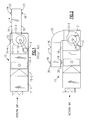
- the numeral 10 generally designates a conventional AHU with conventional duct ANC structure located in duct 14 which is connected to the discharge of fan 12.
- the AHU 10 is typically made up of a plurality of sections and/or subassemblies including mixing box 10-1, filter 10-2, coil 10-3 and fan housing 10-4.
- Fan 12 has a cutoff 12-2 which defines the actual outlet from scroll 12-1 but, as is conventional, the outlet defined at the cutoff discharges into the larger duct 14.
- expansion of the flow is allowed to take place in the duct 14 for a distance equal to three times the diameter of blower 12-3. In that distance the turbulence associated with the fan discharge diminishes along with the associated difficulties with locating sensing microphones 16 in a region where considerable flow generated noise is present.
- a typical duct ANC system can require a ten foot spacing to accommodate the input noise sensing microphones(s) 16, the noise canceling speaker(s) 18 and the error sensing microphone(s) 20.
- blower 12-3 is driven by motor 13 thereby drawing return and makeup air into the AHU, through a heat exchanger defined by coil 10-3 to heat or cool the air and delivering the resultant conditioned air from scroll 12-1 into duct 14.
- the fan noises are sensed by microphone(s) 16 and through circuitry (not illustrated) speaker(s) 18 is driven to produce a signal to cancel the fan noise.
- Microphone(s) 20 sense the result of the noise cancellation by speaker(s) 18 and through circuitry (not illustrated) the output of speaker(s) 18 is corrected.
- the duct ANC system adds ten feet, or so, to the Figure 1 device.
- fan 12 of the Figure 1 device is repositioned to provide a top discharge and 90° elbow 22 is located between blower 12 and duct 14 which employs a conventional ANC system.
- the Figure 2 embodiment eliminates the length added by duct 14 but requires an additional height clearance to accommodate elbow 22 and the duct 14 above AHU 10. Otherwise, the Figure 2 device would operate the same as the Figure 1 device.
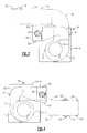
- the present invention reduces the additional space requirements by using the blower discharge at the cutoff 12-2 to define the cross sectional size of the inlet leg of 90° elbow 42. Since the inlet leg of elbow 42 is smaller in cross section than the inlet of elbow 22, the resultant bend is smaller. Additionally, the present invention reduces the cross section in the bend of elbow 42 leading to the downstream leg of the elbow 42 before expanding it at least to the cross section of the entrance of inlet leg and usually expanding it further.
- the present invention also incorporates the ANC system into elbow 42 which requires that the downstream leg of elbow 42 be longer than the inlet leg since the inlet leg is kept as short as possible to minimize the added length/height to the AHU 10.
- elbow 42 which is connected to blower 12 at the outlet defined by cutoff 12-2 provides a significant space saving over the use of elbow 22 and conventional ANC containing duct 14.
- blower 12 reoriented to provide a vertical discharge into ANC elbow 42, it will be seen that a horizontal discharge results but requires much less space than ANC containing duct 14.
- ANC elbow 42 The locating of the ANC structure into elbow 42 depends upon locating the sensing microphone(s) 16 at or near the blower outlet where flow noises due to turbulence normally preclude the placement of the sensing microphone(s) 16.
- the placement of sensing microphone(s) 16 in the region of the blower outlet is possible through the use of the turbulence shields which are the subject of commonly assigned U.S. Patent Application Serial No. 699,674 filed August 30, 1996 and U.S. Patent Application Serial No. 871,020 filed June 6, 1997. Accordingly, ANC elbow 42 can be integrated into AHU 10 / fan 12.
- blower 12 located in fan housing 10-4 which is located at one end of the AHU 10
- fan housing 10-4 which is located at one end of the AHU 10
- the blower 12 is, conventionally, appropriately oriented for the desired discharge.
- the ANC elbow 42 can be located within the fan housing portion 10-4 of AHU 10 with blower 12, or may be external to the fan housing portion 10-4 of AHU 10 and only secured thereto at the blower outlet defined by cutoff 12-2.
- the ANC elbow 42 changes the fan outlet direction by 90° and blower 12 would be repositioned accordingly when ANC elbow 42 is employed.
- FIG 5 illustrates a blower 12 having a bottom horizontal discharge.
- blower 12 has a cutoff 12-2 which defines the actual outlet 12-4 of scroll 12-1.
- the outlet of fan 12 is considered to include portion 12-5 which, together with outlet 12-4, constitutes a cross section corresponding to the cross sectional area of the duct 14 of Figures 1-4.
- the inlet 42-1 of elbow 42 corresponds to outlet 12-4.
- Inlet leg 42-2 of elbow 42 is very short and blends into 90° bend 42-3.
- the 90° bend 42-3 converges in the downstream direction to a throat 42-4 having a cross sectional area less than that of inlet 42-1.
- leg 42-5 diverges so that the outlet 42-6 of elbow 42 is at least as large as inlet 42-1, and usually larger .
- Outlet 42-6 will, upon installation, be connected to a duct which expands in cross section to that corresponding to duct 14 of Figures 1-4.
- input noise sensing microphone(s) 16, speaker(s) 18 and error sensing microphone(s) 20 are connected to controller 60 which, responsive to the fan noise sensed by microphone(s) 16 causes speaker 18 to be driven to produce a noise canceling signal.
- Error sensing microphone(s) 20 sense the result of the noise canceling achieved by speaker 18 and controller 60 corrects the driving of speaker 18 responsive thereto.
- sensing microphone 16 is located proximate inlet 42-1 pursuant to the teachings of Application Serial Number 699,674 and 871,020, which are hereby incorporated by reference, and essentially avoids the turbulence flow associated noise.
- Noise canceling loudspeaker 18 is located in leg 42-5, usually in the full cross sectional area downstream of throat 42-4. However, if the leg 42-5 is long enough, the loudspeaker 18 may be located in the expanding section.
- Error microphone(s) 20 are located near, and preferably opposite or a little downstream of loudspeaker 18.
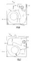
- Figure 6 is identical to Figure 5 except that fan 12 is illustrated within fan housing 10-4 of AHU 10 and the motor 13, controller 60 and circuitry have been omitted.
- ANC elbow 42 is illustrated as located inside of fan housing 10-4 of AHU 10, but it may be located wholly or partially outside of AHU 10 if necessary or desired.
- Figure 7 shows the fan 12 and ANC elbow 42 repositioned relative to the Figure 6 position so as to provide a horizontal rather than a vertical discharge otherwise the structure and operation would be the same.
- elbow 42 is illustrated as a single member, one or more of the legs may be made separate from the bend portion.
- fan and ANC elbow are indicated as part of the AHU, they may be separately made, sold and/or used. It is therefore intended that the scope of the present invention is to be limited only by the scope of the appended claims.
Landscapes
- Engineering & Computer Science (AREA)
- Chemical & Material Sciences (AREA)
- Combustion & Propulsion (AREA)
- Mechanical Engineering (AREA)
- General Engineering & Computer Science (AREA)
- Physics & Mathematics (AREA)
- Acoustics & Sound (AREA)
- Multimedia (AREA)
- Civil Engineering (AREA)
- Soundproofing, Sound Blocking, And Sound Damping (AREA)
- Structures Of Non-Positive Displacement Pumps (AREA)
- Duct Arrangements (AREA)
- Air Conditioning Control Device (AREA)
- Motor Or Generator Cooling System (AREA)
- Exhaust Silencers (AREA)
Applications Claiming Priority (2)
| Application Number | Priority Date | Filing Date | Title |
|---|---|---|---|
| US884231 | 1986-07-10 | ||
| US08/884,231 US6049615A (en) | 1997-06-27 | 1997-06-27 | Intergrated active noise control system for air handling unit |
Publications (2)
| Publication Number | Publication Date |
|---|---|
| EP0887787A2 true EP0887787A2 (de) | 1998-12-30 |
| EP0887787A3 EP0887787A3 (de) | 2001-09-12 |
Family
ID=25384225
Family Applications (1)
| Application Number | Title | Priority Date | Filing Date |
|---|---|---|---|
| EP98630026A Withdrawn EP0887787A3 (de) | 1997-06-27 | 1998-06-12 | Integriertes aktives Lärmkontrollesystem für Luftbehandlungseinheit |
Country Status (9)
| Country | Link |
|---|---|
| US (1) | US6049615A (de) |
| EP (1) | EP0887787A3 (de) |
| JP (1) | JP3086799B2 (de) |
| KR (1) | KR100296569B1 (de) |
| CN (1) | CN1096056C (de) |
| AU (1) | AU739198B2 (de) |
| BR (1) | BR9802298A (de) |
| MY (1) | MY116756A (de) |
| SG (1) | SG71806A1 (de) |
Cited By (3)
| Publication number | Priority date | Publication date | Assignee | Title |
|---|---|---|---|---|
| DE102005057399A1 (de) * | 2005-11-30 | 2007-06-06 | Siemens Ag | Gasströmungserzeuger mit einem Gasauslass und mit einem Stör-schallreduzierer und Verfahren |
| US10371171B2 (en) | 2014-09-22 | 2019-08-06 | Regal Beloit America, Inc. | System and methods for reducing noise in an air moving system |
| EP4246506A1 (de) * | 2022-03-15 | 2023-09-20 | L & T Technology Services Limited | Verfahren und system zur rauschunterdrückung |
Families Citing this family (18)
| Publication number | Priority date | Publication date | Assignee | Title |
|---|---|---|---|---|
| US6850252B1 (en) | 1999-10-05 | 2005-02-01 | Steven M. Hoffberg | Intelligent electronic appliance system and method |
| US6537490B2 (en) * | 2001-05-30 | 2003-03-25 | M & I Heat Transfer Products Ltd. | Air inlet and outlet silencer structures for turbine |
| US6802690B2 (en) | 2001-05-30 | 2004-10-12 | M & I Heat Transfer Products, Ltd. | Outlet silencer structures for turbine |
| TW200826062A (en) * | 2008-01-15 | 2008-06-16 | Asia Vital Components Co Ltd | System of inhibiting broadband noise of communication equipment room |
| US8331577B2 (en) * | 2008-07-03 | 2012-12-11 | Hewlett-Packard Development Company, L.P. | Electronic device having active noise control with an external sensor |
| US9380382B2 (en) | 2010-04-15 | 2016-06-28 | Nortek Air Solutions, Llc | Methods and systems for active sound attenuation in a fan unit |
| WO2011129934A2 (en) * | 2010-04-15 | 2011-10-20 | Huntair, Inc. | Methods and systems for active sound attenuation in an air handling unit |
| US8596050B2 (en) | 2011-08-19 | 2013-12-03 | United Technologies Corporation | Sound attenuating heat exchanger for an internal combustion engine |
| US9841210B2 (en) | 2014-04-22 | 2017-12-12 | Trane International Inc. | Sound level control in an HVAC system |
| US10372092B2 (en) * | 2014-04-22 | 2019-08-06 | Trane International Inc. | System and method for controlling HVAC equipment so as to obtain a desired range of a sound pressure level and/or sound power level |
| JP6722013B2 (ja) * | 2016-03-22 | 2020-07-15 | 株式会社日本クライメイトシステムズ | 車両空調用送風装置 |
| WO2018056711A1 (ko) * | 2016-09-21 | 2018-03-29 | 한온시스템 주식회사 | 차량용 공조장치 |
| KR102309585B1 (ko) * | 2017-04-25 | 2021-10-07 | 한온시스템 주식회사 | 차량용 공조장치 |
| US11164558B2 (en) | 2016-09-21 | 2021-11-02 | Hanon Systems | Vehicular air conditioning system |
| CN110439860B (zh) * | 2018-05-04 | 2025-04-15 | 宁波方太厨具有限公司 | 一种离心风机的蜗壳结构 |
| CN110843831A (zh) * | 2019-11-18 | 2020-02-28 | 中科振声(苏州)电子科技有限公司 | 一种降噪分配箱、空调管路系统及空调 |
| IT202100027719A1 (it) * | 2021-10-28 | 2023-04-28 | Ask Ind Spa | Apparato per la riduzione del rumore generato da dispositivi di movimentazione o condizionamento d’aria, e veicolo comprendente un tale apparato |
| US12025338B2 (en) * | 2022-06-08 | 2024-07-02 | Hewlett-Packard Development Company, L.P. | Noise cancellation based on airflow generator operational speed |
Family Cites Families (6)
| Publication number | Priority date | Publication date | Assignee | Title |
|---|---|---|---|---|
| JPH0261450A (ja) * | 1988-08-24 | 1990-03-01 | Matsushita Electric Ind Co Ltd | 空気調和機の消音装置 |
| JPH03188798A (ja) * | 1989-12-19 | 1991-08-16 | Hitachi Plant Eng & Constr Co Ltd | 電子消音システム |
| WO1993002445A1 (en) * | 1991-07-16 | 1993-02-04 | Noise Cancellation Technologies, Inc. | High efficiency fan with adaptive noise cancellation |
| JPH06242787A (ja) * | 1993-02-17 | 1994-09-02 | Fujitsu Ltd | 回り込み音制御式能動騒音消去装置 |
| JP2750084B2 (ja) * | 1993-05-19 | 1998-05-13 | 三星電子株式会社 | 真空掃除機の騒音制御装置 |
| DE4408278A1 (de) * | 1994-03-11 | 1995-09-14 | Gaggenau Werke | Dunstabzugshaube mit wenigstens teilweiser Auslöschung des Lüftergeräusches |
-
1997
- 1997-06-27 US US08/884,231 patent/US6049615A/en not_active Expired - Fee Related
-
1998
- 1998-06-12 EP EP98630026A patent/EP0887787A3/de not_active Withdrawn
- 1998-06-18 SG SG1998001465A patent/SG71806A1/en unknown
- 1998-06-18 CN CN98115008A patent/CN1096056C/zh not_active Expired - Fee Related
- 1998-06-26 KR KR1019980024370A patent/KR100296569B1/ko not_active Expired - Fee Related
- 1998-06-26 BR BR9802298-9A patent/BR9802298A/pt not_active Application Discontinuation
- 1998-06-26 AU AU73244/98A patent/AU739198B2/en not_active Ceased
- 1998-06-26 MY MYPI98002917A patent/MY116756A/en unknown
- 1998-06-29 JP JP10181724A patent/JP3086799B2/ja not_active Expired - Fee Related
Cited By (5)
| Publication number | Priority date | Publication date | Assignee | Title |
|---|---|---|---|---|
| DE102005057399A1 (de) * | 2005-11-30 | 2007-06-06 | Siemens Ag | Gasströmungserzeuger mit einem Gasauslass und mit einem Stör-schallreduzierer und Verfahren |
| WO2007062889A3 (de) * | 2005-11-30 | 2007-07-26 | Siemens Ag | Gasströmungserzeuger mit einem gasauslass und mit einem störschallreduzierer und verfahren zur störschallreduzierung |
| DE102005057399B4 (de) * | 2005-11-30 | 2015-12-24 | Siemens Aktiengesellschaft | Gasströmungserzeuger mit einem Gasauslass und mit einem Stör-schallreduzierer und Verfahren |
| US10371171B2 (en) | 2014-09-22 | 2019-08-06 | Regal Beloit America, Inc. | System and methods for reducing noise in an air moving system |
| EP4246506A1 (de) * | 2022-03-15 | 2023-09-20 | L & T Technology Services Limited | Verfahren und system zur rauschunterdrückung |
Also Published As
| Publication number | Publication date |
|---|---|
| BR9802298A (pt) | 1999-11-09 |
| KR100296569B1 (ko) | 2001-09-22 |
| JP3086799B2 (ja) | 2000-09-11 |
| AU7324498A (en) | 1999-01-07 |
| JPH11101492A (ja) | 1999-04-13 |
| EP0887787A3 (de) | 2001-09-12 |
| KR19990007384A (ko) | 1999-01-25 |
| CN1096056C (zh) | 2002-12-11 |
| CN1204017A (zh) | 1999-01-06 |
| US6049615A (en) | 2000-04-11 |
| MY116756A (en) | 2004-03-31 |
| SG71806A1 (en) | 2000-04-18 |
| AU739198B2 (en) | 2001-10-04 |
Similar Documents
| Publication | Publication Date | Title |
|---|---|---|
| US6049615A (en) | Intergrated active noise control system for air handling unit | |
| US6342005B1 (en) | Active noise control for plug fan installations | |
| US6142732A (en) | Fan scroll | |
| US9458860B2 (en) | Fan with sound-muffling box | |
| CN106091106A (zh) | 顶棚埋入型空气调节器 | |
| JP5147508B2 (ja) | 換気送風機 | |
| US4877106A (en) | Sound-attenuating discharge apparatus for a packaged terminal air conditioner | |
| US20020168933A1 (en) | Low noise duct system | |
| CN101680666A (zh) | 模块化通风系统 | |
| JPH07190415A (ja) | 空気調和機 | |
| EP0600031A1 (de) | Aussenseitiges teilgehäuse für geteiltes klimagerät. | |
| EP0961087B1 (de) | Spirale für Gebläse | |
| JP4779554B2 (ja) | ダクトファン | |
| JP4670273B2 (ja) | ダクトファン | |
| HK1016678A (en) | Integrated active noise control system for air handling unit | |
| CN210187230U (zh) | 一种碾米机消音结构及其碾米机 | |
| WO2023181528A1 (ja) | 個室ブース | |
| JP3590411B2 (ja) | 天吊カセット形空気調和機 | |
| JPH06307691A (ja) | 床下空調対応送風機 | |
| JPH09170786A (ja) | 空気調和機の室外機 | |
| JP3199931B2 (ja) | 空調機の室外機 | |
| JP7583982B2 (ja) | 空調ユニット | |
| CN1232214C (zh) | 吸尘器 | |
| JP2753186B2 (ja) | 換気装置 | |
| JPH07190469A (ja) | セントラル空調用ダクト構造 |
Legal Events
| Date | Code | Title | Description |
|---|---|---|---|
| PUAI | Public reference made under article 153(3) epc to a published international application that has entered the european phase |
Free format text: ORIGINAL CODE: 0009012 |
|
| AK | Designated contracting states |
Kind code of ref document: A2 Designated state(s): AT BE CH CY DE DK ES FI FR GB GR IE IT LI LU MC NL PT SE Kind code of ref document: A2 Designated state(s): DE ES FR GB IT |
|
| AX | Request for extension of the european patent |
Free format text: AL;LT;LV;MK;RO;SI |
|
| PUAL | Search report despatched |
Free format text: ORIGINAL CODE: 0009013 |
|
| AK | Designated contracting states |
Kind code of ref document: A3 Designated state(s): AT BE CH CY DE DK ES FI FR GB GR IE IT LI LU MC NL PT SE |
|
| AX | Request for extension of the european patent |
Free format text: AL;LT;LV;MK;RO;SI |
|
| 17P | Request for examination filed |
Effective date: 20020214 |
|
| AKX | Designation fees paid |
Free format text: DE ES FR GB IT |
|
| 17Q | First examination report despatched |
Effective date: 20031217 |
|
| RAP1 | Party data changed (applicant data changed or rights of an application transferred) |
Owner name: CARRIER CORPORATION |
|
| GRAP | Despatch of communication of intention to grant a patent |
Free format text: ORIGINAL CODE: EPIDOSNIGR1 |
|
| GRAP | Despatch of communication of intention to grant a patent |
Free format text: ORIGINAL CODE: EPIDOSNIGR1 |
|
| STAA | Information on the status of an ep patent application or granted ep patent |
Free format text: STATUS: THE APPLICATION IS DEEMED TO BE WITHDRAWN |
|
| 18D | Application deemed to be withdrawn |
Effective date: 20090324 |