EP0887546B1 - Zündvorrichtung für Brennkraftmaschine - Google Patents
Zündvorrichtung für Brennkraftmaschine Download PDFInfo
- Publication number
- EP0887546B1 EP0887546B1 EP98111520A EP98111520A EP0887546B1 EP 0887546 B1 EP0887546 B1 EP 0887546B1 EP 98111520 A EP98111520 A EP 98111520A EP 98111520 A EP98111520 A EP 98111520A EP 0887546 B1 EP0887546 B1 EP 0887546B1
- Authority
- EP
- European Patent Office
- Prior art keywords
- voltage
- ignition
- zener diode
- ignition coil
- diode
- Prior art date
- Legal status (The legal status is an assumption and is not a legal conclusion. Google has not performed a legal analysis and makes no representation as to the accuracy of the status listed.)
- Expired - Lifetime
Links
Images


Classifications
-
- F—MECHANICAL ENGINEERING; LIGHTING; HEATING; WEAPONS; BLASTING
- F02—COMBUSTION ENGINES; HOT-GAS OR COMBUSTION-PRODUCT ENGINE PLANTS
- F02P—IGNITION, OTHER THAN COMPRESSION IGNITION, FOR INTERNAL-COMBUSTION ENGINES; TESTING OF IGNITION TIMING IN COMPRESSION-IGNITION ENGINES
- F02P3/00—Other installations
- F02P3/02—Other installations having inductive energy storage, e.g. arrangements of induction coils
- F02P3/04—Layout of circuits
- F02P3/05—Layout of circuits for control of the magnitude of the current in the ignition coil
- F02P3/051—Opening or closing the primary coil circuit with semiconductor devices
Definitions
- the present invention relates to an ignition device for an internal combustion engine.
- Conventional methods for suppressing an induced voltage generated at a lower-voltage end of a secondary winding of an ignition coil at a primary current supply timing include a method using a high-voltage diode connected to a higher-voltage end of the secondary winding as described in Japanese Patent Laid-open No. 55-66659 and a method using a Zener diode connected to a lower-voltage end of the secondary winding, the Zener diode coming into conduction at a reverse voltage higher than the induced voltage generated at the lower-voltage end of the secondary winding as described in Japanese Patent Publication No. 6-94864.
- US 4 653 460 A which is considered to represent the closest prior art, an ignition system for an internal combustion engine is described, wherein a Zener diode is used with a Zener voltage higher than the voltage induced at the low voltage side of a secondary winding to prevent the occurence of plug firing due to the secondary induced high voltage.
- the diode used has a breakdown voltage higher than the induced voltage generated at the lower-voltage end of the secondary winding at the primary current supply timing. Accordingly, the diode is configured by using an element having a high withstand voltage.
- the use of the diode. having a breakdown voltage higher than the induced voltage generated at the lower-voltage end of the secondary winding at the primary current supply timing requires an element having a high withstand voltage.
- a diode having a high withstand voltage is expensive and bulky, causing a disadvantage in view of cost and space.
- the diode is used for the purpose of preventing sparking of a spark plug by the induced voltage generated at the lower-voltage end of the secondary winding at the primary current supply timing. That is, the breakdown voltage of the diode is not necessarily set to a level higher than the induced voltage generated at the primary current supply timing, but the object can be achieved by using a Zener diode to offset the induced voltage to such a level that no spark discharge occurs even at a voltage lower than the induced voltage, thereby reducing a voltage between electrodes of a spark plug.
- the object of the present invention can be achieved by using a relatively low-voltage Zener diode that is inexpensive and less bulky.
- a Zener diode is connected to the lower-voltage end of the secondary winding of an ignition coil.
- the Zener diode comes into conduction at a reverse voltage lower than the induced voltage generated at the lower-voltage end of the secondary winding at the primary current supply timing, and has a Zener voltage necessary and enough to prevent misignition in a spark plug. Accordingly, even when an induced voltage is generated at the primary current supply timing, the generation of a spark in the spark plug can be prevented.
- a discharge voltage between electrodes of the spark plug is about 300 V or higher according to the theory of Paschen or about 1 kV or higher according to the practice in an automotive internal combustion engine. Accordingly, the Zener voltage is set on the basis of these voltage values to prevent the misignition.
- the Zener diode Since the Zener diode is connected to the lower-voltage end of the secondary winding, the induced voltage at the primary current supply timing is offset by the Zener voltage, and the reverse voltage in the secondary winding is divided between the Zener diode and a discharge gap of the spark plug, thereby suppressing the discharge voltage in the spark plug. Further, since the Zener diode is connected to the lower-voltage end of the secondary winding, the Zener diode is not affected by a capacitive discharge current sparking through a secondary capacitance to the spark plug upon ignition at the primary current cutoff timing, thereby preventing the Zener diode from undergoing high voltage.
- FIG. 1 shows a typical configuration of an ignition system having no reverse voltage blocking diode.
- the ignition system shown in FIG. 1 includes a battery 1, an ECU 2, an ignition coil 3, a spark plug 4, and a power transistor 5.
- the ECU 2 outputs from its output stage HIGH and LOW pulses to the base of the power transistor 5 at a proper ignition timing, thereby switching the power transistor 5 on and off to generate a high voltage on the secondary side of the ignition coil 3.
- the ignition coil 3 includes a primary winding 6 having one end connected to the positive electrode of the battery 1 and the other end connected to the collector of the power transistor 5, and a secondary winding 7 having a higher-voltage end connected to one end of the spark plug 4 and the other lower-voltage end connected to the ground or to the positive electrode of the battery 1.
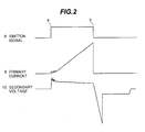
- FIG. 2 shows waveforms of operation of the ignition system shown in FIG. 1.
- Reference numeral 8 denotes an ignition signal output from the ECU 2;
- reference numeral 9 denotes a primary current flowing in the primary winding 6 of the ignition coil 3;
- reference numeral 10 denotes a secondary voltage generated-in the secondary winding 7 of the ignition coil 3 and applied to the spark plug 4.
- the ignition signal 8 becomes HIGH at a proper ignition timing computed by the ECU 2, and simultaneously the primary current 9 starts flowing with a delay corresponding to the time constant for the inductance and resistance of the primary winding 6.
- the ignition signal 8 becomes LOW at a proper ignition timing b, and the primary current 9 is cut off to generate a high voltage at the higher-voltage end of the secondary winding 7 of the ignition coil 3.
- spark discharge required for ignition occurs at a negative secondary voltage generated at the current cutoff timing b
- a positive reverse voltage of about 1000 to 2000 V is also induced at the higher-voltage end of the secondary winding 7 at the current supply timing a.
- FIG. 3 shows a typical configuration of an ignition coil 11 having a reverse voltage blocking diode embedded at the higher-voltage end.
- the ignition coil 11 has a primary winding 12 and a secondary winding 13 magnetically coupled together through an iron core.
- the secondary winding 13 has a higher-voltage end connected through a high-voltage diode 15 to one end of a spark plug 14 and the other lower-voltage end connected to the ground or to the positive electrode of a battery.
- the diode 15 always undergoes a breakover voltage and an arc voltage upon ignition and a high induced voltage at the primary current supply timing. Further, a capacitive discharge current due to secondary capacitance in the ignition coil 11 flows in the diode 15. Accordingly, the diode 15 is in a greatly harsh environment.
- FIG. 4 shows the configuration of an ignition system according to a preferred embodiment of the present invention.
- the ignition system shown in FIG. 4 includes a battery 16, an ECU 17, an ignition coil 18, a spark plug 19, a power transistor 20, and a Zener diode 23.
- the ignition coil 18 includes a primary winding 21 having one end connected to the positive electrode of the battery 16 and the other end connected to the collector of the power transistor 20 and a secondary winding 22 having a higher-voltage end connected to one end of the spark plug 19 and a lower-voltage end connected to the anode of the Zener diode 23.
- the cathode of the Zener diode 23 is connected to the ground or to the one end of the primary winding 21 (the positive electrode of the battery 16).
- the present invention is characterized in that the Zener voltage of the Zener diode 23 is set to a value slightly lower than an induced voltage generated at a primary current supply timing.
- FIG. 5 shows an example of differences in induced voltage according to the Zener voltage of the Zener diode 23.
- Reference numeral 24 denotes an ignition signal output from the ECU 17;
- reference numeral 25 denotes a primary current;
- reference numeral 26 denotes a secondary voltage waveform in the case that the secondary lower-voltage end of the ignition coil 18 is connected directly to the ground;
- reference numeral 27 denotes a secondary voltage waveform in the case that the secondary lower-voltage end of the ignition coil 18 is connected to the Zener diode 23 having a Zener voltage of 400 V;
- reference numeral 28 denotes a secondary voltage waveform in the case that the secondary lower-voltage end of the ignition coil 18 is connected to the Zener diode 23 having a Zener voltage of 800 V; and
- reference numeral 29 denotes a secondary voltage waveform in the case that the secondary lower-voltage end of the ignition coil 18 is connected to the Zener diode 23 having a Zener voltage of 2000 V.
- the induced voltage depends on the specifications of the ignition coil, the induced voltage can be changed by selecting the Zener voltage. Accordingly, misignition by a reverse spark possibly generated in the spark plug can be prevented by using the Zener diode having a withstand voltage lower than the induced voltage. For example, in the case that the battery voltage is 14 V and the ratio of turns in the coil is 100, the secondary voltage becomes 1400 V. Assuming that the sparking voltage is 1000 V or higher according to the theory of Paschen and the practice in an automotive internal combustion engine, it is sufficient to select a Zener diode having a Zener voltage of 400 V or higher. Further, assuming that the sparking voltage is 300 V or higher, it is sufficient to select a Zener diode having a Zener voltage of 1100 V or higher.
- the diode is not affected by a capacitive discharge current.
- the high-voltage diode is affected by load and heat due to a capacitive discharge current.
- the Zener diode 23 in this preferred embodiment is hardly affected.
- the high-voltage diode In the case that a high-voltage diode is embedded at the higher-voltage end of the ignition coil, the high-voltage diode always undergoes a breakover voltage and an arc voltage upon sparking and an induced voltage at a primary current supply timing.
- the Zener diode in this preferred embodiment undergoes only an induced voltage at a primary current supply timing, thus taking an advantage in view of deterioration.
- the high-voltage diode is essential to block an induced voltage at a primary current supply timing and withstand a spark. plug open voltage.
- the Zener diode is connected to the secondary lower-voltage end of the ignition coil in this preferred embodiment, such a high-voltage diode is not especially required because the Zener diode comes into conduction at a voltage beyond the Zener voltage.
- the misignition of the spark plug can be prevented by setting a proper value of the Zener voltage lower than the induced voltage. Accordingly, a diode having a lower withstand voltage can be used, thereby allowing provision of an ignition device advantageous in view of cost and space.
- the Zener diode provided on the secondary lower-voltage side of the ignition coil according to the present invention may be embedded in the ignition coil or may be mounted in the ignition system.
- the present invention is effective especially in an independent ignition system such that a single spark plug and a single ignition coil are provided for each cylinder.
- the lower-voltage ends of the secondary windings of all the ignition coils may be commonly connected through the above-mentioned Zener diode to the ground or to one end of each primary winding (the positive electrode of the battery), thereby allowing a reduction in parts count and cost.
- an induced voltage generated at a primary current supply timing can be suppressed to a level lower than that in the case of not providing a reverse voltage blocking diode, thereby preventing the misignition of a spark plug due to the induced voltage. Further, by using a low-voltage Zener diode, it is possible to provide an ignition device advantageous in view of cost and space.
Claims (5)
- Zündvorrichtung für eine Brennkraftmaschine zur Erzeugung einer Hochspannung in einer Sekundärwicklung (22) einer Zündspule (18) durch Ein- und Ausschalten eines Schaltelements gemäß einem Zündsteuersignal ausgegeben von einer elektronischen Steuereinheit (ECU) für die Brennkraftmaschine, zur Ein/Aus-Steuerung eines durch eine Primärwicklung (21) fließenden Primärstroms der Zündspule (18) mit,
einer Zenerdiode (23), die mit einem niederspannungsseitigen Ende der Sekundärwicklung (22) der Zündspule (18) in Sperrrichtung zu der während des Beginns der Primärstromzuführung induzierten Spannung verbunden ist, die induzierte Spannung ist als Produkt der Spannungsänderung zwischen den gegenüberliegenden Enden der Primärwicklung und einem Wicklungsverhältnis der Zündspule (18) definiert,
dadurch gekennzeichnet, dass
die Zenerdiode (23) bei einer kleineren Spannung als die induzierte Spannung leitend wird. - Zündvorrichtung gemäß Anspruch 1, dadurch gekennzeichnet, dass die Zenerdiode (23) bei einer Spannung, größer als die Spannungsdifferenz zwischen der Funkenspannung und der während des Beginns der Primärstromzuführung auf der Niederspannungsseite der Sekundärwicklung der Zündspule (18) induzierten Spannung, leitend wird.
- Zündvorrichtung gemäß Anspruch 1, dadurch gekennzeichnet, dass die Zenerspannung der Zenerdiode (23) auf ein Niveau unterhalb der während der Zeiten der Primärstromzuführung induzierten Spannung gesetzt wird und Fehlzündungen in der Zündkerze (19) verhindert werden.
- Zündvorrichtung gemäß Anspruch 1, dadurch gekennzeichnet, dass die Zenerspannung der Zenerdiode (23) entsprechend dem Wichtungsverhältnis der Zündspule (18) zwischen 300 V und 1000 V eingestellt wird.
- Zündvorrichtung gemäß Anspruch 3, dadurch gekennzeichnet, dass die Werte des Niveaus auf Paschens Gesetz basieren.
Applications Claiming Priority (3)
| Application Number | Priority Date | Filing Date | Title |
|---|---|---|---|
| JP170497/97 | 1997-06-26 | ||
| JP17049797A JP3533313B2 (ja) | 1997-06-26 | 1997-06-26 | 内燃機関用点火装置 |
| JP17049797 | 1997-06-26 |
Publications (3)
| Publication Number | Publication Date |
|---|---|
| EP0887546A2 EP0887546A2 (de) | 1998-12-30 |
| EP0887546A3 EP0887546A3 (de) | 2000-10-11 |
| EP0887546B1 true EP0887546B1 (de) | 2003-05-02 |
Family
ID=15906067
Family Applications (1)
| Application Number | Title | Priority Date | Filing Date |
|---|---|---|---|
| EP98111520A Expired - Lifetime EP0887546B1 (de) | 1997-06-26 | 1998-06-23 | Zündvorrichtung für Brennkraftmaschine |
Country Status (4)
| Country | Link |
|---|---|
| US (1) | US6082344A (de) |
| EP (1) | EP0887546B1 (de) |
| JP (1) | JP3533313B2 (de) |
| DE (1) | DE69813953T2 (de) |
Families Citing this family (5)
| Publication number | Priority date | Publication date | Assignee | Title |
|---|---|---|---|---|
| US6666196B2 (en) * | 2002-01-10 | 2003-12-23 | Delphi Technologies, Inc. | Ignition system having improved spark-on-make blocking diode implementation |
| DE10260321B4 (de) * | 2002-12-20 | 2016-10-20 | Volkswagen Ag | Schaltungsanordnung zur Funkentstörung einer Kraftfahrzeugzündanlage |
| US20080257324A1 (en) * | 2006-12-22 | 2008-10-23 | Brp Us Inc. | Inductive ignition system for internal combustion engine |
| JP5516895B2 (ja) * | 2008-02-07 | 2014-06-11 | セム アクティエボラグ | Cdiシステムにおけるエネルギ支援のためのシステム |
| US8286617B2 (en) | 2010-12-23 | 2012-10-16 | Grady John K | Dual coil ignition |
Family Cites Families (7)
| Publication number | Priority date | Publication date | Assignee | Title |
|---|---|---|---|---|
| GB1510556A (en) * | 1975-11-28 | 1978-05-10 | Hitachi Ltd | Ignition system for an internal combustion engine |
| JPS5566659A (en) * | 1978-09-05 | 1980-05-20 | Nippon Denso Co Ltd | Ignition device for internal combustion engine |
| JPS6040866Y2 (ja) * | 1979-11-06 | 1985-12-10 | 株式会社デンソー | 内燃機関用点火装置 |
| JPS56124671A (en) * | 1980-03-07 | 1981-09-30 | Hitachi Ltd | Igniting apparatus |
| JPH0694864B2 (ja) * | 1984-07-26 | 1994-11-24 | 日本電装株式会社 | 内燃機関用点火装置 |
| JPH0694864A (ja) * | 1992-09-11 | 1994-04-08 | Japan Atom Energy Res Inst | 核融合装置用真空容器のポート開口部構造 |
| JPH10176647A (ja) * | 1996-12-19 | 1998-06-30 | Denso Corp | 点火コイル |
-
1997
- 1997-06-26 JP JP17049797A patent/JP3533313B2/ja not_active Expired - Lifetime
-
1998
- 1998-06-23 EP EP98111520A patent/EP0887546B1/de not_active Expired - Lifetime
- 1998-06-23 DE DE69813953T patent/DE69813953T2/de not_active Expired - Lifetime
- 1998-06-26 US US09/105,273 patent/US6082344A/en not_active Expired - Lifetime
Also Published As
| Publication number | Publication date |
|---|---|
| DE69813953D1 (de) | 2003-06-05 |
| EP0887546A2 (de) | 1998-12-30 |
| JPH1113614A (ja) | 1999-01-19 |
| DE69813953T2 (de) | 2004-05-13 |
| US6082344A (en) | 2000-07-04 |
| EP0887546A3 (de) | 2000-10-11 |
| JP3533313B2 (ja) | 2004-05-31 |
Similar Documents
| Publication | Publication Date | Title |
|---|---|---|
| EP0457383B1 (de) | Zündungssystem mit Zündkerze | |
| GB2085076A (en) | Plasma ignition system | |
| GB2085523A (en) | Plasma ignition system | |
| US7005855B2 (en) | Device to provide a regulated power supply for in-cylinder ionization detection by using the ignition coil fly back energy and two-stage regulation | |
| EP0228840A2 (de) | Impuls-Erzeuger-Schaltung für Zündsysteme | |
| EP3374626B1 (de) | Verfahren und vorrichtung zur steuerung eines zündsystems | |
| EP3374627B1 (de) | Verfahren und vorrichtung zur steuerung eines zündsystems | |
| US20120055456A1 (en) | Method for generating corona discharges in two combustion chambers of a combustion engine | |
| EP0183223B1 (de) | Elektronische Zündanlage für Brennkraftmaschine | |
| EP0887546B1 (de) | Zündvorrichtung für Brennkraftmaschine | |
| JP5253144B2 (ja) | 内燃機関用点火装置 | |
| US4177782A (en) | Ignition system providing sparks for two ignition plugs in each cylinder from a single ignition coil | |
| JPH0694864B2 (ja) | 内燃機関用点火装置 | |
| EP0663526B1 (de) | Zündsystem einer inneren Brennkraftmaschine | |
| US6684866B2 (en) | Ignition system for an internal combustion engine | |
| EP0370301B1 (de) | Zündanlage mit induktive Ausladung bei Brennkraftmaschinen | |
| JPH11153079A (ja) | 点火装置 | |
| US11560869B2 (en) | Electronic circuit and capacitor discharge system comprising electronic circuit | |
| US11898528B2 (en) | Ignition device | |
| JP2927128B2 (ja) | コンデンサ放電式多気筒内燃機関用点火装置 | |
| US6899092B2 (en) | System and method for increasing spark current to spark plugs | |
| JPS62210262A (ja) | パルス発生回路とそれを用いた点火装置 | |
| SU848731A1 (ru) | Система электронного зажигани | |
| RU2123132C1 (ru) | Катушка зажигания | |
| JPS61272467A (ja) | 内燃機関用無接点点火装置 |
Legal Events
| Date | Code | Title | Description |
|---|---|---|---|
| PUAI | Public reference made under article 153(3) epc to a published international application that has entered the european phase |
Free format text: ORIGINAL CODE: 0009012 |
|
| AK | Designated contracting states |
Kind code of ref document: A2 Designated state(s): DE FR GB IT |
|
| AX | Request for extension of the european patent |
Free format text: AL;LT;LV;MK;RO;SI |
|
| PUAL | Search report despatched |
Free format text: ORIGINAL CODE: 0009013 |
|
| AK | Designated contracting states |
Kind code of ref document: A3 Designated state(s): AT BE CH CY DE DK ES FI FR GB GR IE IT LI LU MC NL PT SE |
|
| AX | Request for extension of the european patent |
Free format text: AL;LT;LV;MK;RO;SI |
|
| 17P | Request for examination filed |
Effective date: 20010205 |
|
| AKX | Designation fees paid |
Free format text: DE FR GB IT |
|
| 17Q | First examination report despatched |
Effective date: 20011002 |
|
| GRAH | Despatch of communication of intention to grant a patent |
Free format text: ORIGINAL CODE: EPIDOS IGRA |
|
| GRAH | Despatch of communication of intention to grant a patent |
Free format text: ORIGINAL CODE: EPIDOS IGRA |
|
| GRAA | (expected) grant |
Free format text: ORIGINAL CODE: 0009210 |
|
| AK | Designated contracting states |
Designated state(s): DE FR GB IT |
|
| REG | Reference to a national code |
Ref country code: GB Ref legal event code: FG4D |
|
| REF | Corresponds to: |
Ref document number: 69813953 Country of ref document: DE Date of ref document: 20030605 Kind code of ref document: P |
|
| ET | Fr: translation filed | ||
| PLBE | No opposition filed within time limit |
Free format text: ORIGINAL CODE: 0009261 |
|
| STAA | Information on the status of an ep patent application or granted ep patent |
Free format text: STATUS: NO OPPOSITION FILED WITHIN TIME LIMIT |
|
| 26N | No opposition filed |
Effective date: 20040203 |
|
| PGFP | Annual fee paid to national office [announced via postgrant information from national office to epo] |
Ref country code: IT Payment date: 20080423 Year of fee payment: 11 |
|
| PGFP | Annual fee paid to national office [announced via postgrant information from national office to epo] |
Ref country code: FR Payment date: 20080523 Year of fee payment: 11 |
|
| PGFP | Annual fee paid to national office [announced via postgrant information from national office to epo] |
Ref country code: GB Payment date: 20080528 Year of fee payment: 11 |
|
| GBPC | Gb: european patent ceased through non-payment of renewal fee |
Effective date: 20090623 |
|
| REG | Reference to a national code |
Ref country code: FR Ref legal event code: ST Effective date: 20100226 |
|
| PG25 | Lapsed in a contracting state [announced via postgrant information from national office to epo] |
Ref country code: FR Free format text: LAPSE BECAUSE OF NON-PAYMENT OF DUE FEES Effective date: 20090630 |
|
| PG25 | Lapsed in a contracting state [announced via postgrant information from national office to epo] |
Ref country code: GB Free format text: LAPSE BECAUSE OF NON-PAYMENT OF DUE FEES Effective date: 20090623 |
|
| PG25 | Lapsed in a contracting state [announced via postgrant information from national office to epo] |
Ref country code: IT Free format text: LAPSE BECAUSE OF NON-PAYMENT OF DUE FEES Effective date: 20090623 |
|
| PGFP | Annual fee paid to national office [announced via postgrant information from national office to epo] |
Ref country code: DE Payment date: 20170621 Year of fee payment: 20 |
|
| REG | Reference to a national code |
Ref country code: DE Ref legal event code: R071 Ref document number: 69813953 Country of ref document: DE |