EP0887508B1 - Venetian blind with lowerable head assembly - Google Patents
Venetian blind with lowerable head assembly Download PDFInfo
- Publication number
- EP0887508B1 EP0887508B1 EP98111686A EP98111686A EP0887508B1 EP 0887508 B1 EP0887508 B1 EP 0887508B1 EP 98111686 A EP98111686 A EP 98111686A EP 98111686 A EP98111686 A EP 98111686A EP 0887508 B1 EP0887508 B1 EP 0887508B1
- Authority
- EP
- European Patent Office
- Prior art keywords
- motor
- sunshade device
- rail
- tilting
- bar
- Prior art date
- Legal status (The legal status is an assumption and is not a legal conclusion. Google has not performed a legal analysis and makes no representation as to the accuracy of the status listed.)
- Expired - Lifetime
Links
Images


Classifications
-
- E—FIXED CONSTRUCTIONS
- E06—DOORS, WINDOWS, SHUTTERS, OR ROLLER BLINDS IN GENERAL; LADDERS
- E06B—FIXED OR MOVABLE CLOSURES FOR OPENINGS IN BUILDINGS, VEHICLES, FENCES OR LIKE ENCLOSURES IN GENERAL, e.g. DOORS, WINDOWS, BLINDS, GATES
- E06B9/00—Screening or protective devices for wall or similar openings, with or without operating or securing mechanisms; Closures of similar construction
- E06B9/24—Screens or other constructions affording protection against light, especially against sunshine; Similar screens for privacy or appearance; Slat blinds
- E06B9/26—Lamellar or like blinds, e.g. venetian blinds
- E06B9/28—Lamellar or like blinds, e.g. venetian blinds with horizontal lamellae, e.g. non-liftable
- E06B9/30—Lamellar or like blinds, e.g. venetian blinds with horizontal lamellae, e.g. non-liftable liftable
- E06B9/32—Operating, guiding, or securing devices therefor
- E06B9/327—Guides for raisable lamellar blinds with horizontal lamellae
Definitions
- the invention relates to a sun protection system when retracted into a package gathered horizontal Slats on a turning device to adjust their inclination hanging on one with the help of elevator elements movable reversible rail is mounted.
- Sun protection systems with horizontal slats - also venetian blinds called - usually work according to the same system.
- the slats are on both sides by a kind of ladder forming support elements, usually cords, or one Loop cord held over which the slat curtain attaches a turning device often integrated in a housing hangs.
- a bottom rail is used to retract the curtain pulled up by elevator elements, with the slats one after the other on this lower rail to form a package stack.
- a venetian blind is already known from US Pat. No. 5,443,108, its turning rail together with a turning device mounted on it can be moved by elevator elements. Disadvantageous with this construction is that the manual drive the turning device only installation on one Inside of the window allowed and no automatic setting the slat inclination, such as for the Use in office buildings is essential to be realized can. This allows the advantage of a movable reversing rail, that in reducing the space required is above the window area, only very limited deploy.
- the object of the invention is a sun protection system to create that has a movable reversible rail and is universally applicable.
- the task is performed by a sun protection system of the type described above, in which in an electric motor is provided on the turning rail, which at least drives the turning device and the one to a supply source in the reversing rail or over free hanging or windable supply lines or via sliding contacts, that run on side tracks, to one external supply source is connected.
- the arrangement of the drive motor in the reversing rail allows a remote control for the control of the slat inclination for example from the interior of the room, so that the sun protection system easily mounted on the outside of windows can be.
- the problem of powering an electric motor according to the invention in the movable turning rail solved by one of the proposed variants.
- a motor drives in the turning rail on the elevator elements.
- a housing for the window area to be shaded that receives the drive motor for the elevator elements.
- the lowest slat is usually above support elements connected with a bottom rail. This can be below the surface to be shaded or fixed Help from catch-up elements mounted on the reversing rail be windable with a motor.
- the slat curtain below the window area to be shaded In the variant with fixed assembled bottom rail is gathered together the slat curtain below the window area to be shaded.
- the second variant with regardless of the Reversible lower rail can be the shirring of the Package at any desired location in the travel area of the two rails. This variant enables very variable shading of the window surface, so that e.g. also a cutout in the middle of the window area can be shaded.
- a single motor drives the turning device, the elevator elements and / or the catch-up elements accomplished.
- the distribution of the drive torque the motor to the individual elements can be switched Couplings, slip clutches, freewheels or the like.
- it is easily possible instead of one Motor in the reversing rail for driving the elevator elements or catch-up elements usual constructions with fixed built-in elevator motors or manual elevator devices with the motor-driven according to the invention Turning mechanism in the movable turning rail combine.
- the control of the at least one electric motor in the Reversible rail is preferably a cordless Signal receiver from the supply source of the motor is fed with.
- the wireless control of the electric motors avoids additional control cables and offers different ones Possibilities of manual or automatic Control.
- the drive of the turning bearings of the turning device and the Elevator rolls of the elevator elements are of a kind and Way, as from the usual combined turning and pull-out drives for sun protection systems with overhead Slat package is known.
- the drive motor takes the turning bearings and thus the Support elements on which the slats are suspended, only over a certain angle of rotation up to a stop.
- a slip clutch ensures for the fact that the elevator rollers, despite the blocked
- the turning bearing can continue to rotate, so that the lamella curtain can be retracted or extended.
- the catch-up elements to the drive motor be coupled in the turning rail, for example the drive torque of the motor optionally on the elevator elements or the catch-up elements works.
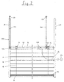
- Fig. 1 shows a first embodiment of a sun protection system 10. A cross section of this sun protection system is in Fig. 5 shown.
- the sun protection system 10 has a turning rail 12 with Spiral bearings 14, which carry supporting elements 16 guided over them.
- the actual curtain of the sun protection system 10 is formed by lamellae 18, each over their support elements 16 running past both longitudinal sides in a certain Hang the distance to the adjacent slats 18.
- the turning rail 12 has lateral guide bolts 20, with the help of which they are in lateral guide rails 22 is guided flexibly.
- the slats 18 have alternately Guide bolts 24 on their left and right sides. Alternatively for this it would be conceivable not to have all the lamellae 18 Guide bolts 24, some with guide bolts on both sides 24 to be provided.
- the turning rail 12 is suspended from elevator elements 26, e.g. on the guide pin 20 (see left half of Fig. 1) or in a central attachment point 28 (see Fig. 5) can be attached to the housing 30 of the turning rail 12.
- the elevator elements 26 are above by deflecting rollers 32 deflected the travel range of the turning rail 12 and are connected to elevator rollers 34 below the slats 18.
- the two elevator rollers 34 are driven by a drive shaft 36 driven by a motor 38.
- the elevator elements 26 can be tapes made of textiles, perforated plastic or metal, but also chains.
- the turning rail 12 also takes one Reversible motor 40, the reversible bearing via a drive shaft 42 14 drives a supply source 44 for the Power supply to the turning motor 40 and a signal receiving unit 46 on, with the aid of which the turning motor 40 is controlled can be.
- the supply source 44 can, for example be an accumulator connected via contacts (not shown) the reversible rail 12 is rechargeable, which is completely after below driven reversing rail 12 with live stationary contacts (not shown) are in contact.
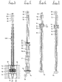
- the turning bearings 14 can a certain angle of rotation between two stop positions can be rotated (see Fig. 5 to 7).
- Fig. 5 shows in cross section a horizontal position of the Slats 18, in which the turning bearing 14 in one middle position between the two stop positions are located and the support members 16 on both long sides of the Slats 18 of the same length omitted from the reversing rail 12 are.
- Fig. 7 shows the reversible bearing 14 in its opposite Stop position in which the support elements in comparison omitted to the position of FIG. 6 in the reverse manner or caught up. Even with this position of the turning bearings 14 results in a closed curtain position of the slats 18, but with the inverted position of the individual slats 18.
- Fig. 7 also shows an alternative location of the Drive motor 38 above the guide rails 22.
- the deflection rollers 32 can be dispensed with at the same time, however, the space requirement increases because of the 22 between the two guide rails transverse drive shaft. This is usually common integrated with the motor 38 in a top rail, so that the space requirement in the upper area of the sun protection system 10 increases.
- the drive of the reversible bearing 14 could be shown in FIG. 1 Embodiment instead of a separate turning motor 40 also with the help of a drive shaft 42 seated gear (not shown) take place with a Rack cooperates in the side guide rail 22.
- the driving shaft 14 is carried along by the drive shaft 42 takes place when the turning rail 12 moves up or down then via a slip clutch or the like Change the direction of movement of the turning rail 12 that Takes the turning bearing up to its stop and thereby the Slats adjusted in their inclination. Will the turning rail 12 move further in this direction, the drive shaft 42 thanks to the slip clutch relative to the turning bearing 14 turn.
- the reversible bearings 14 via a slip clutch or the like acting elements coupled to the drive shaft 42.
- the drive shaft 42 continues to drive elevator rollers 134, to which elevator elements 126 when the reversing rail is raised 12 can be wound up. Hold the elevator elements 126 the turning rail 12 in its current position and are in relation to when moving the turning rail 12 are not moved onto the side guide rails 22, at attachment points 50 above the sun protection system 110 attached.
- the power supply of the combined drive and reversing motor 140 does not have one in the reversing rail 12 housed supply source but about a supply line 56 connected to a voltage source 54 connected.
- the signal receiver 46 can at such control of the motor 140 is eliminated.
- the supply line 56 can hang freely, resiliently or be designed to be windable on a winding roll.
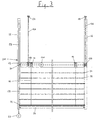
- FIG. 3 shows a further possibility of the engine 140 to supply with electricity.
- the rest of the structure corresponds the sun protection system 210 shown in FIG. 3 from Fig. 2.
- the Power supply via 22 extending in the side guide rails Busbars 58 (see also FIGS. 4 and 8) that connected at its lower end to a voltage source 60 are.
- the turning and elevator motor 140 is via supply lines 256 connected to sliding contacts 62, which with contact the busbars 58.
- the Sliding contacts 62 via spring elements 64, which they against the Press busbars 58.
- FIG. 1 represents two variants of the arrangement of the elevator elements.
- FIG. 8 shows the cross-sectional shape of the guide rail 22 evident. In cross section, it has three longitudinal chambers 68, 70 accessible from the outside through narrow slots 66 are, the middle chamber 68 the guide pin 20th of the reversing rail and the two outer chambers 70 each take up a busbar 58 and as a guideway serve for the sliding contacts 62. To only one if possible needing simple insulation of the busbars 58 works the reversible and elevator motor 140 preferably with low voltages.
- FIG. 4 shows - as an example - the sun protection system 210 in FIG fully retracted condition.
- the slats 18 rest a package 22 gathered on a lower rail 74 that on Mounting bracket 76 rests or over this the inner walls a shaft 78 is attached.
- the shaft 78 is closed by a cover 80 in the retracted state, attached to the top of the turning rail 12 is.
- the cover 80 in a shoulder 82 on the top of the shaft 78.
- the shaft 78 forms together with the Cover 80 a protection against the ingress of water and Dirt, which is particularly because of the arranged in the shaft 78 electrical components is particularly important, however also counteracts premature contamination of the slats 18.
- the turning rail 12 is in the half-extended Position shown, in which only a part of the slats 18 folded as a package rests on the lower rail 74.
- the illustration of shaft 78 was shown in this figure waived.
- FIGS. 6 and 7 show the turning rail 12 in the maximum extended position Position. All slats are in this position 18 lifted off the lower rail 74 and form one hanging curtain. The lowest slat 18 is on the lower rail 74, e.g. B. fixed on the support elements to the Stabilize the curtain additionally. Also an immediate one Attachment of the lowest slat 18 on the shaft 78 or the Building wall is conceivable.
- FIG. 9 is a modification of that shown in Fig. 3 Sun protection system 210 shown.
- This sun protection system 310 differs from that shown in FIG. 3 Sun protection system 210 in that the lower rail 374 not rigidly attached below the area to be shaded but movable in the side guide rails 22 is performed.
- To the bottom rail 374 regardless of the The sun protection system has the ability to move the reversing rail 12 310 via combined elevator / turning bracket 314, which is a raising of the curtain with the help of the motor 140 enable.
- the elevator rollers 134 with the help of which the Reversible rail is movable, correspond in their design the embodiment shown in Fig.
- the coupling to the motor 140 is preferably carried out via a switchable coupling to either the reversing rail 12 or move the lower rail 374 in the guide rails 22 to be able to.
- the power supply to the motor 140 corresponds the embodiment shown in FIG. 3.
- Fig. 9 allows a flexible Shading of the window surface because the curtain is gathered 72 at any desired point in the travel range can.
- the limit switch for each for opening and closing the reversible rail 12 responsible motor 38, 140 can by Switch sensors attached to the motor or separately positioned Limit switches are made directly by the turning rail 12 are started and triggered. Basically are all previously known variants of a limit switch also to the sun protection systems 10 described here, 110, 210 transferable.
- the control of the motors can be done in the presence a signal receiver 46 by wireless infrared or Radio signal transmitters take place, or, in the case of fixed supply lines or busbars, via ordinary switches.
- sun protection systems all have the advantage that unlike usual Sun protection systems above the window area to be shaded little or no installation space required is.
Landscapes
- Engineering & Computer Science (AREA)
- Structural Engineering (AREA)
- Architecture (AREA)
- Civil Engineering (AREA)
- Operating, Guiding And Securing Of Roll- Type Closing Members (AREA)
- Blinds (AREA)
- Power-Operated Mechanisms For Wings (AREA)
- Types And Forms Of Lifts (AREA)
Abstract
Description
Die Erfindung befaßt sich mit einer Sonnenschutzanlage mit in eingefahrenem Zustand zu einem Paket gerafften, horizontalen Lamellen, die an einer Wendeeinrichtung zu ihrer Neigungsverstellung hängen, die an einer mit Hilfe von Aufzugselementen verfahrbaren Wendeschiene montiert ist.The invention relates to a sun protection system when retracted into a package gathered horizontal Slats on a turning device to adjust their inclination hanging on one with the help of elevator elements movable reversible rail is mounted.
Sonnenschutzanlagen mit horizontalen Lamellen - auch Raffstore genannt - arbeiten meist nach dem gleichen System. Die Lamellen sind beidseitig durch gemeinsam eine Art Leiter bildende Tragelemente, normalerweise Schnüre, oder eine Schlaufenkordel gehalten, über die der Lamellenbehang an einer häufig in einem Gehäuse integrierten Wendeeinrichtung hängt. Zum Einfahren des Behangs wird eine Unterschiene durch Aufzugselemente nach oben gezogen, wobei sich die Lamellen nacheinander auf dieser Unterschiene zu einem Paket stapeln.Sun protection systems with horizontal slats - also venetian blinds called - usually work according to the same system. The slats are on both sides by a kind of ladder forming support elements, usually cords, or one Loop cord held over which the slat curtain attaches a turning device often integrated in a housing hangs. A bottom rail is used to retract the curtain pulled up by elevator elements, with the slats one after the other on this lower rail to form a package stack.
Aus der US-PS 5,443,108 ist bereits ein Raffstore bekannt, dessen Wendeschiene mitsamt einer an ihr montierten Wendeeinrichtung durch Aufzugselemente verfahrbar ist. Nachteilig bei dieser Konstruktion ist, daß der manuelle Antrieb der Wendeeinrichtung lediglich den Einbau auf einer Fensterinnenseite erlaubt und keine automatische Einstellung der Lamellenneigung, wie sie beispielsweise für den Einsatz in Bürogebäuden unerläßlich ist, realisiert werden kann. Damit läßt sich der Vorteil einer verfahrbaren Wendeschiene, der in der Reduzierung des erforderlichen Platzes oberhalb der Fensterfläche liegt, nur sehr begrenzt einsetzen. A venetian blind is already known from US Pat. No. 5,443,108, its turning rail together with a turning device mounted on it can be moved by elevator elements. Disadvantageous with this construction is that the manual drive the turning device only installation on one Inside of the window allowed and no automatic setting the slat inclination, such as for the Use in office buildings is essential to be realized can. This allows the advantage of a movable reversing rail, that in reducing the space required is above the window area, only very limited deploy.
Die Aufgabe der Erfindung besteht darin, eine Sonnenschutzanlage zu schaffen, die eine verfahrbare Wendeschiene aufweist und universell einsetzbar ist.The object of the invention is a sun protection system to create that has a movable reversible rail and is universally applicable.
Erfindungsgemäß wird die Aufgabe durch eine Sonnenschutzanlage der eingangs beschriebenen Art gelöst, bei welcher in der Wendeschiene ein Elektromotor vorgesehen ist, der wenigstens die Wendeeinrichtung antreibt und der an eine Versorgungsquelle in der Wendeschiene oder über frei hängende oder aufwickelbare Versorgungsleitungen oder über Schleifkontakte, die auf seitlichen Stromschienen laufen, an eine externe Versorgungsquelle angeschlossen ist.According to the invention, the task is performed by a sun protection system of the type described above, in which in an electric motor is provided on the turning rail, which at least drives the turning device and the one to a supply source in the reversing rail or over free hanging or windable supply lines or via sliding contacts, that run on side tracks, to one external supply source is connected.
Die Anordnung des Antriebsmotors in der Wendeschiene erlaubt eine Fernbedienung der Steuerung der Lamellenneigung beispielsweise vom Rauminneren, so daß die Sonnenschutzanlage problemlos auf den Außenseiten von Fenstern montiert werden kann. Das Problem der Stromversorgung eines Elektromotors in der verfahrbaren Wendeschiene wird erfindungsgemäß durch eine der vorgeschlagenen Varianten gelöst.The arrangement of the drive motor in the reversing rail allows a remote control for the control of the slat inclination for example from the interior of the room, so that the sun protection system easily mounted on the outside of windows can be. The problem of powering an electric motor according to the invention in the movable turning rail solved by one of the proposed variants.
In bevorzugter Ausführungsform der Erfindung treibt ein Motor in der Wendeschiene die Aufzugselemente an. Bei dieser Variante ist es nicht notwendig, oberhalb oder unterhalb der zu verschattenden Fensterfläche ein Gehäuse vorzusehen, das den Antriebsmotor für die Aufzugselemente aufnimmt. Damit läßt sich der Platzbedarf der Sonnenschutzanlage insbesondere oberhalb der zu verschattenden Fensterfläche weiter reduzieren.In a preferred embodiment of the invention, a motor drives in the turning rail on the elevator elements. At this Variant it is not necessary above or below to provide a housing for the window area to be shaded, that receives the drive motor for the elevator elements. In order to the space requirement of the sun protection system in particular above the window area to be shaded to reduce.
Überlicherweise ist die unterste Lamelle über Tragelemente mit einer Unterschiene verbunden. Diese kann unterhalb der zu verschattenden Fläche feststehend angeordnet oder mit Hilfe von an der Wendeschiene montierten Aufholelementen mit einem Motor aufziehbar sein. Bei der Variante mit feststehend montierter Unterschiene erfolgt das Zusammenraffen des Lamellenbehangs unterhalb der zu verschattenden Fensterfläche. Bei der zweiten Variante mit unabhängig von der Wendeschiene verfahrbarer Unterschiene kann das Raffen des Paketes grundsätzlich an jeder gewünschten Stelle im Verfahrbereich der beiden Schienen erfolgen. Diese Variante ermöglicht eine sehr variable Verschattung der Fensterfläche, so daß z.B. auch ein Ausschnitt in der Mitte der Fensterfläche verschattet werden kann.The lowest slat is usually above support elements connected with a bottom rail. This can be below the surface to be shaded or fixed Help from catch-up elements mounted on the reversing rail be windable with a motor. In the variant with fixed assembled bottom rail is gathered together the slat curtain below the window area to be shaded. In the second variant with regardless of the Reversible lower rail can be the shirring of the Package at any desired location in the travel area of the two rails. This variant enables very variable shading of the window surface, so that e.g. also a cutout in the middle of the window area can be shaded.
Um das Gewicht der Wendeschiene und ihren Bauraum gering zu halten, ist in bevorzugter Ausführungsform der Erfindung vorgesehen, daß ein einziger Motor den Antrieb der Wendeeinrichtung, der Aufzugselemente und/oder der Aufholelemente bewerkstelligt. Die Verteilung des Antriebsmoments des Motors zu den einzelnen Elementen kann über schaltbare Kupplungen, Rutschkupplungen, Freiläufe oder dgl. erfolgen. Selbstverständlich ist es ohne weiteres möglich, statt eines Motors in der Wendeschiene zum Antrieb der Aufzugselemente bzw. Aufholelemente übliche Konstruktionen mit ortsfest eingebauten Aufzugsmotoren oder manuellen Aufzugsvorrichtungen mit dem erfindungsgemäßen motorisch angetriebenen Wendemechanismus in der verfahrbaren Wendeschiene zu kombinieren.To keep the weight of the reversible rail and its installation space low hold is in a preferred embodiment of the invention provided that a single motor drives the turning device, the elevator elements and / or the catch-up elements accomplished. The distribution of the drive torque the motor to the individual elements can be switched Couplings, slip clutches, freewheels or the like. Of course it is easily possible instead of one Motor in the reversing rail for driving the elevator elements or catch-up elements usual constructions with fixed built-in elevator motors or manual elevator devices with the motor-driven according to the invention Turning mechanism in the movable turning rail combine.
Die Ansteuerung des wenigstens einen Elektromotors in der Wendeschiene erfolgt vorzugsweise über einen schnurlosen Signalempfänger, der von der Versorgungsquelle des Motors mit gespeist ist. Die schnurlose Ansteuerung der Elektromotoren vermeidet zusätzliche Steuerkabel und bietet verschiedene Möglichkeiten der manuellen oder automatischen Ansteuerung. The control of the at least one electric motor in the Reversible rail is preferably a cordless Signal receiver from the supply source of the motor is fed with. The wireless control of the electric motors avoids additional control cables and offers different ones Possibilities of manual or automatic Control.
Bei einer in der Wendeschiene integrierten Versorgungsquelle des Elektromotors besteht diese vorzugsweise aus einem Akkumulator, der über Kontrakte an der Wendeschiene aufladbar ist, die im eingefahrenen Zustand der Anlage mit einer Spannungsquelle in Verbindung stehen. Der Vorteil dieser Variante liegt darin, daß keine stromführenden Teile einer Bewegung ausgesetzt sind und daher nicht mit Kontaktproblemen, Kabelbrüchen oder dgl. gerechnet werden muß.With a supply source integrated in the reversing rail of the electric motor, this preferably consists of a Accumulator that contracts on the reversing rail is rechargeable with the system retracted connected to a voltage source. The advantage this variant is that no live parts are exposed to movement and therefore not with contact problems, Cable breaks or the like must be expected.
Bei einer Versorgungsspannung im Niedervoltbereich ist es auch denkbar, daß die Aufzugselemente Versorgungsleitungen bilden.With a supply voltage in the low voltage range it is also conceivable that the elevator elements supply lines form.
Der Antrieb der Wendelager der Wendeeinrichtung und der Aufzugsrollen der Aufzugselemente erfolgt in einer Art und Weise, wie sie aus den bisher üblichen kombinierten Wende- und Auszugsantrieben bei Sonnenschutzanlagen mit oben liegendem Lamellenpaket bekannt ist. Bei einem derartigen Antrieb nimmt der Antriebsmotor die Wendelager und damit die Tragelemente, an denen die Lamellen aufgehängt sind, nur über einen bestimmten Drehwinkel bis zu einem Anschlag mit. Wird der Antriebsmotor weiter betätigt, sorgt eine Rutschkupplung dafür, daß sich die Aufzugsrollen trotz der blokkierten Wendelager weiter drehen können, so daß der Lamellenbehang ein- bzw. ausgefahren werden kann. In ähnlicher Art und Weise können die Aufholelemente an den Antriebsmotor in der Wendeschiene gekoppelt sein, wobei beispielsweise das Antriebsmoment des Motors wahlweise auf die Aufzugselemente oder die Aufholelemente wirkt.The drive of the turning bearings of the turning device and the Elevator rolls of the elevator elements are of a kind and Way, as from the usual combined turning and pull-out drives for sun protection systems with overhead Slat package is known. With such a drive the drive motor takes the turning bearings and thus the Support elements on which the slats are suspended, only over a certain angle of rotation up to a stop. If the drive motor is operated further, a slip clutch ensures for the fact that the elevator rollers, despite the blocked The turning bearing can continue to rotate, so that the lamella curtain can be retracted or extended. More like that Way, the catch-up elements to the drive motor be coupled in the turning rail, for example the drive torque of the motor optionally on the elevator elements or the catch-up elements works.
Nachfolgend wird anhand der beigefügten Zeichnungen näher auf Ausführungsbeispiele der Erfindung eingegangen. Es zeigen:
- Fig. 1
- eine teilgeschnittene, schematische Ansicht einer Sonnenschutzanlage mit getrenntem Wende- und Aufzugsantrieb;
- Fig. 2
- eine teilgeschnittene, schematische Ansicht einer Sonnenschutzanlage mit kombiniertem Wende- und Aufzugsantrieb;
- Fig. 3
- eine Sonnenschutzanlage nach Fig. 2 mit geänderter Stromzufuhr;
- Fig. 4
- einen Querschnitt der Sonnenschutzanlage nach Fig. 3 in eingefahrenem Zustand;
- Fig. 5
- einen Querschnitt der Sonnenschutzanlage nach Fig. 1 in halb ausgefahrenem Zustand;
- Fig. 6
- einen Querschnitt der Sonnenschutzanlage nach Fig. 2 in ausgefahrener Stellung;
- Fig. 7
- einen Querschnitt einer weiteren Sonnenschutzanlage in ausgefahrenem Zustand mit invertierter Lamellenstellung;
- Fig. 8
- einen Schnitt der Wendeschiene der Sonnenschutzanlage nach Fig. 3 zur Verdeutlichung der Stromzufuhr und
- Fig. 9
- eine Sonnenschutzanlage nach Fig. 3 mit aufholbarer Unterschiene.
- Fig. 1
- a partially sectioned, schematic view of a sun protection system with separate turning and elevator drive;
- Fig. 2
- a partially sectioned, schematic view of a sun protection system with a combined turning and elevator drive;
- Fig. 3
- a sun protection system according to Figure 2 with changed power supply.
- Fig. 4
- a cross section of the sun protection system of Figure 3 in the retracted state.
- Fig. 5
- a cross section of the sun protection system of Figure 1 in the half-extended state.
- Fig. 6
- a cross section of the sun protection system of Figure 2 in the extended position.
- Fig. 7
- a cross section of another sun protection system in the extended state with inverted slat position;
- Fig. 8
- a section of the turning rail of the sun protection system of FIG. 3 to illustrate the power supply and
- Fig. 9
- a sun protection system according to Fig. 3 with a retractable bottom rail.
Fig. 1 zeigt eine erste Ausführungsform einer Sonnenschutzanlage
10. Ein Querschnitt dieser Sonnenschutzanlage ist in
Fig. 5 dargestellt.Fig. 1 shows a first embodiment of a
Die Sonnenschutzanlage 10 besitzt eine Wendeschiene 12 mit
Wendelagern 14, die über sie geführte Tragelemente 16 mitnehmen.
Der eigentliche Behang der Sonnenschutzanlage 10
wird von Lamellen 18 gebildet, die über jeweils an ihren
beiden Längsseiten vorbeilaufende Tragelemente 16 in bestimmtem
Abstand zu den benachbarten Lamellen 18 hängen.The
Die Wendeschiene 12 verfügt über seitliche Führungsbolzen
20, mit deren Hilfe sie in seitlichen Führungsschienen 22
beweglich geführt ist. Die Lamellen 18 besitzen abwechselnd
Führungsbolzen 24 auf ihrer linken und rechten Seite. Alternativ
hierzu wäre es denkbar, nicht alle Lamellen 18 mit
Führungsbolzen 24, einige jedoch beidseitig mit Führungsbolzen
24 zu versehen.The turning
Die Wendeschiene 12 ist an Aufzugselementen 26 aufgehängt,
die z.B. am Führungsbolzen 20 (siehe linke Hälfte von Fig.
1) oder in einem mittigen Befestigungspunkt 28 (siehe Fig.
5) am Gehäuse 30 der Wendeschiene 12 befestigt sein können.
Die Aufzugselemente 26 werden durch Umlenkrollen 32 oberhalb
des Verfahrbereichs der Wendeschiene 12 umgelenkt und
sind mit Aufzugsrollen 34 unterhalb der Lamellen 18 verbunden.
Die beiden Aufzugsrollen 34 werden über eine Antriebswelle
36 von einem Motor 38 angetrieben. Die Aufzugselemente
26 können Bänder aus Textilien, gelochtem Kunststoff
oder Metall, aber auch Ketten sein. The turning
Neben den Wendelagern 14 nimmt die Wendeschiene 12 auch einen
Wendemotor 40, der über eine Antriebswelle 42 die Wendelager
14 antreibt, eine Versorgungsquelle 44 für die
Stromversorgung des Wendemotors 40 und eine Signalempfangseinheit
46 auf, mit Hilfe derer der Wendemotor 40 gesteuert
werden kann. Die Versorgungsquelle 44 kann beispielsweise
ein Akkumulator sein, der über Kontakte (nicht gezeigt) an
der Wendeschiene 12 aufladbar ist, die bei vollständig nach
unten gefahrener Wendeschiene 12 mit spannungsführenden
ortsfesten Kontakten (nicht gezeigt) in Berührung stehen.
Mit Hilfe des Wendemotors 40 können die Wendelager 14 um
einen bestimmten Drehwinkel zwischen zwei Anschlagpositionen
verdreht werden (siehe Fig. 5 bis 7).In addition to the turning
Fig. 5 zeigt im Querschnitt eine waagerechte Stellung der
Lamellen 18, bei welcher sich die Wendelager 14 in einer
mittleren Stellung zwischen den beiden Anschlagspositionen
befinden und die Tragelemente 16 auf beiden Längsseiten der
Lamellen 18 in gleicher Länge aus der Wendeschiene 12 ausgelassen
sind.Fig. 5 shows in cross section a horizontal position of the
Bei der in Fig. 6 gezeigten ersten Anschlagstellung der Wendelager 14 ergibt sich durch die einseitig maximal ausgelassenen und auf der anderen Seite maximal eingeholten Tragelemente und die maximal geneigten Lamellen 18 eine geschlossene Stellung des Behangs.In the first stop position shown in FIG Turning bearing 14 results from the maximum omitted on one side and on the other hand caught up to the maximum Support elements and the maximum inclined slats 18 a closed Position of the curtain.
Fig. 7 zeigt die Wendelager 14 in ihrer entgegengesetzten
Anschlagsstellung, in welcher die Tragelemente im Vergleich
zur Stellung nach Fig. 6 in umgekehrter Weise ausgelassen
bzw. eingeholt sind. Auch bei dieser Stellung der Wendelager
14 ergibt sich eine geschlossene Behangstellung der Lamellen
18, jedoch mit invertierter Lage der einzelnen Lamellen
18. Fig. 7 zeigt weiterhin eine alternative Lage des
Antriebsmotors 38 oberhalb der Führungsschienen 22. Bei
dieser Ausführungsform kann auf die Umlenkrollen 32 verzichtet
werden, gleichzeitig erhöht sich jedoch der Platzbedarf
wegen der zwischen den beiden Führungsschienen 22
quer verlaufenden Antriebswelle. Diese ist gewöhnlich gemeinsam
mit dem Motor 38 in eine Oberschiene integriert, so
daß der Platzbedarf im oberen Bereich der Sonnenschutzanlage
10 zunimmt.Fig. 7 shows the
Die in Fig. 6 dargestellte Antriebsalternative des Aufzugs wird in Zusammenhang mit Fig. 2 später näher erläutert.The drive alternative of the elevator shown in FIG. 6 will be explained later in connection with FIG. 2.
Der Antrieb der Wendelager 14 könnte bei der in Fig. 1 dargestellten
Ausführungsform statt durch einen separaten Wendemotor
40 auch mit Hilfe eines auf der Antriebswelle 42
sitzenden Zahnrades (nicht gezeigt) erfolgen, das mit einer
Zahnstange in der seitlichen Führungsschiene 22 zusammenwirkt.
Die Mitnahme der Wendelager 14 durch die Antriebswelle
42 beim Auf- oder Abfahren der Wendeschiene 12 erfolgt
dann über eine Rutschkupplung oder dgl., die bei einer
Änderung der Bewegungsrichtung der Wendeschiene 12 das
Wendelager bis zu seinem Anschlag mitnimmt und dadurch die
Lamellen in ihrer Neigung verstellt. Wird die Wendeschiene
12 weiter in dieser Richtung verfahren, kann sich die Antriebswelle
42 dank der Rutschkupplung relativ zu dem Wendelager
14 drehen.The drive of the
Auch bei der in Fig. 2 dargestellten Sonnenschutzanlage 110
sind die Wendelager 14 über eine Rutschkupplung oder ähnlich
wirkende Elemente mit der Antriebswelle 42 gekoppelt.
Die Antriebswelle 42 treibt weiterhin Aufzugsrollen 134 an,
auf welche Aufzugselemente 126 beim Auffahren der Wendeschiene
12 aufwickelbar sind. Die Aufzugselemente 126 halten
die Wendeschiene 12 in ihrer momentanen Position und
sind, da sie beim Verfahren der Wendeschiene 12 in Bezug
auf die seitlichen Führungsschienen 22 nicht bewegt werden,
an Befestigungspunkten 50 oberhalb der Sonnenschutzanlage
110 angebracht.Also in the
Im Gegensatz zu der in Fig. 1 dargestellten Sonnenschutzanlage
10 erfolgt die Stromversorgung des kombinieren Antriebs-
und Wendemotors 140 nicht über eine in der Wendeschiene
12 untergebrachte Versorgungsquelle sondern über
eine Versorgungsleitung 56, die an eine Spannungsquelle 54
angeschlossen ist. Der Signalempfänger 46 kann bei einer
derartigen Ansteuerung des Motors 140 entfallen. Die Versorgungsleitung
56 kann frei hängend, elastisch nachgiebig
oder auf einer Wickelrolle aufwickelbar ausgeführt sein.In contrast to the sun protection system shown in FIG. 1
10 the power supply of the combined drive
and reversing
Bei einer Niederspannungsversorgung des Motors 140 ist es
auch denkbar, die Aufzugselemente 126 als Versorgungsleitungen
zu nutzen. Die Spannung könnte dann im Bereich der
Aufzugsrollen 134 abgegriffen werden.It is with a low voltage supply to the
Fig. 3, 4 und 8 zeigen eine weitere Möglichkeit, den Motor
140 mit Strom zu versorgen. Im übrigen Aufbau entspricht
die in Fig. 3 abgebildete Sonnenschutzanlage 210 derjenigen
aus Fig. 2. Bei der Sonnenschutzanlage 210 erfolgt die
Stromzufuhr über in den seitlichen Führungsschienen 22 verlaufende
Stromschienen 58 (siehe auch Fig. 4 und 8), die an
ihrem unteren Ende an eine Spannungsquelle 60 angeschlossen
sind. Der Wende- und Aufzugsmotor 140 ist über Versorgungsleitungen
256 mit Schleifkontakten 62 verbunden, die mit
den Stromschienen 58 in Kontakt stehen. Um immer eine sichere
Anlage zwischen den Schleifkontakten 62 und den zugehörigen
Stromschienen 58 sicherzustellen, verfügen die
Schleifkontakte 62 über Federelemente 64, die sie gegen die
Stromschienen 58 pressen. 3, 4 and 8 show a further possibility of the
Fig. 2 stellt ebenso wie Fig. 3 zwei Varianten der Anordnung
der Aufzugselemente dar. Entsprechend auch der in Fig.
1 abgebildeten Sonnenschutzanlage 10 können die Aufzugselemente
126 im Bereich der Führungsschienen 22 verdeckt geführt
sein, oder sie können offen oberhalb der Wendeschiene
12 vor der zu verschattenden Fläche verlaufen.2, like FIG. 3, represents two variants of the arrangement
of the elevator elements. Correspondingly, also that in FIG.
1 shown
Aus Fig. 8 ist die Querschnittsform der Führungsschiene 22
ersichtlich. Im Querschnitt besitzt sie drei Längskammern
68, 70, die durch schmale Schlitze 66 von außen zugänglich
sind, wobei die mittlere Kammer 68 den Führungsbolzen 20
der Wendeschiene führt und die beiden äußeren Kammern 70
jeweils eine Stromschiene 58 aufnehmen und als Führungsbahn
für die Schleifkontakte 62 dienen. Um nur eine möglichst
einfache Isolierung der Stromschienen 58 zu benötigen, arbeitet
der Wende- und Aufzugsmotor 140 vorzugsweise mit
niedrigen Spannungen.8 shows the cross-sectional shape of the
Fig. 4 bis 7, auf die bereits im Zusammenhang mit den verschiedenen
Antrieben Bezug genommen wurde, zeigen, wie die
Lamellen 18, die im eingefahrenen Zustand zu einem Paket 72
zusammengerafft sind, zu einem Behang aufziehbar sind. Fig.
4 zeigt - als Beispiel - die Sonnenschutzanlage 210 in
vollständig eingefahrenem Zustand. Die Lamellen 18 ruhen zu
einem Paket 22 gerafft auf einer Unterschiene 74, die auf
Befestigungswinkeln 76 aufliegt oder über diese den Innenwänden
eines Schachtes 78 befestigt ist. Der Schacht 78
wird im eingefahrenen Zustand von einer Abdeckung 80 verschlossen,
die an der Oberseite der Wendeschiene 12 angebracht
ist. Beim vollständigen Einfahren der Lamellen legt
sich die Abdekkung 80 in einen Absatz 82 an der Oberseite
des Schachtes 78. Der Schacht 78 bildet zusammen mit der
Abdeckung 80 einen Schutz vor dem Eindringen von Wasser und
Schmutz, was insbesondere wegen der in dem Schacht 78 angeordneten
elektrischen Bauteile besonders wichtig ist, aber
auch einer vorzeitigen Verschmutzung der Lamellen 18 entgegenwirkt.4 to 7, already in connection with the various
Drives referred to show how the
In Fig. 5 ist die Wendeschiene 12 in halb ausgefahrener
Stellung gezeigt, in welcher nur noch ein Teil der Lamellen
18 als Paket zusammengelegt auf der Unterschiene 74 ruht.
Auf die Darstellung des Schachtes 78 wurde in dieser Abbildung
verzichtet.5, the turning
Fig. 6 und 7 zeigen die Wendeschiene 12 in maximal ausgefahrener
Stellung. In dieser Stellung sind sämtliche Lamellen
18 von der Unterschiene 74 abgehoben und bilden einen
hängenden Behang. Die unterste Lamelle 18 ist an der Unterschiene
74, z. B. über die Tragelemente, fixiert, um den
Behang zusätzlich zu stabilisieren. Auch eine unmittelbare
Befestigung der untersten Lamelle 18 am Schacht 78 oder der
Gebäudewand ist denkbar.6 and 7 show the turning
In Fig. 9 ist eine Abwandlung der in Fig. 3 dargestellten
Sonnenschutzanlage 210 dargestellt. Diese Sonnenschutzanlage
310 unterscheidet sich von der in Fig. 3 abgebildeten
Sonnenschutzanlage 210 dadurch, daß die Unterschiene 374
nicht starr unterhalb der zu verschattenden Fläche befestigt
sondern beweglich in den seitlichen Führungsschienen
22 geführt ist. Um die Unterschiene 374 unabhängig von der
Wendeschiene 12 verfahren zu können, verfügt die Sonnenschutzanlage
310 über kombinierte Aufzugs- /Wendela-ger
314, die ein Aufziehen des Behangs mit Hilfe des Motors 140
ermöglichen. Die Aufzugsrollen 134, mit Hilfe derer die
Wendeschiene verfahrbar ist, entsprechen in ihrer Ausführung
der in Fig. 3 dargestellten Ausführungsform, die Ankopplung
an den Motor 140 erfolgt jedoch vorzugsweise über
eine schaltbare Kupplung, um wahlweise die Wendeschiene 12
oder die Unterschiene 374 in den Führungsschienen 22 verfahren
zu können. Die Stromversorgung des Motors 140 entspricht
dabei ebenfalls der in Fig. 3 dargestellten Ausführungsform.In Fig. 9 is a modification of that shown in Fig. 3
Die in Fig. 9 dargestellte Variante erlaubt eine flexible Verschattung der Fensterfläche, da das Raffen des Behangs 72 an jeder gewünschten Stelle im Verfahrbereich erfolgen kann.The variant shown in Fig. 9 allows a flexible Shading of the window surface because the curtain is gathered 72 at any desired point in the travel range can.
Die Endabschaltung des jeweils für das Auf- und Abfahren
der Wendeschiene 12 zuständigen Motors 38, 140 kann durch
am Motor angebrachte Schaltfühler oder separat positionierte
Endschalter erfolgen, die unmittelbar durch die Wendeschiene
12 angefahren und ausgelöst werden. Grundsätzlich
sind alle bisher bekannten Varianten einer Endabschaltung
auch auf die hier beschriebenen Sonnenschutzanlagen 10,
110, 210 übertragbar.The limit switch for each for opening and closing
the
Die Steuerung der Motoren kann im Falle des Vorhandenseins
eines Signalempfängers 46 durch drahtlose Infrarot- oder
Funksignalgeber erfolgen, oder, im Falle fester Versorgungsleitungen
oder Stromschienen, über gewöhnliche Schalter.The control of the motors can be done in the presence
a
Die gezeigten Ausführungsbeispiele von Sonnenschutzanlagen besitzen alle den Vorteil, daß im Gegensatz zu üblichen Sonnenschutzanlagen oberhalb der zu verschattenden Fensterfläche kein bzw. nur sehr geringer Bauraum erforderlich ist.The shown embodiments of sun protection systems all have the advantage that unlike usual Sun protection systems above the window area to be shaded little or no installation space required is.
Claims (10)
- Sunshade device having horizontal slats (18) arranged to be collapsible as a package (72) in a retracted position, said slats (18) being suspended on a tilting mechanism (14, 16, 42) for adjusting their slope, the latter being mounted on a moveable tilting bar (12) by means of tilting means (26; 126), characterized in that said tilting bar (12) is provided with an electric motor (40; 140) driving at least the tilting mechanism (14, 16, 42) and being connected with a power source (44) in the tilting bar (12) or with an external power source (54; 60) by means of supply lines being suspended freely or reelable or wire sliding contacts (62) running on lateral conductor rails (58).
- Sunshade device according to claim 1, characterized in that a motor (140) in said tilting bar (12) drives the lifting means (26; 126).
- Sunshade device according to claim 1 or 2, characterized in that the lowermost slat is connected with a lower bar (74; 374) by means of support means (16), said lower bar (74; 374) being fixedly arranged below the plane to be shaded or said lower bar (74, 374) being liftable by a motor (140) by means of lifting elements (314) mounted on said tilting bar (12).
- Sunshade device according to one of the claims 1 to 3, characterized in that one single motor (140) provides for the driving of said tilting mechanism (14, 16, 42), said lifting means (26; 126) and/or said lifting elements (314).
- Sunshade device according to claim 4, characterized in that the driving torque of the motor (140) is divided by means of switchable clutches, slipping clutches, freewheels and the like to the different units (14, 16, 42; 26; 126; 314).
- Sunshade device according to one of the preceding claims, characterized in that said lifting means comprise belts (26, 126), strings, chains or the like being mounted on said tilting bar, respectively, or alternatively comprise gear elements on said tilting bar (12) cooperating with a gear cutting provided in lateral guiding rails.
- Sunshade device according to one of the preceding claims, characterized in that at least one electric motor (140) is controlled by a wireless signal receiver (46) powered by said power source (44; 54; 60) of said motor (140).
- Sunshade device according to one of the preceding claims, characterized in that the power source (44) comprises an accumulator being rechargeable by means of contacts arranged on said tilting bar and being connected with a supply terminal when the device is in its retracted position.
- Sunshade device according to one of the preceding claims, characterized in that the distribution voltage has a low voltage level and said lifting means (26; 126) form supply lines.
- Sunshade device according to one of the preceding claims, characterized in that said tilting bar (12) is movable in the upward direction by a spring biassed shaft arranged in an upper bar and is movable in the downward direction by a motor against the force of said shaft.
Applications Claiming Priority (2)
| Application Number | Priority Date | Filing Date | Title |
|---|---|---|---|
| DE19727379A DE19727379A1 (en) | 1997-06-27 | 1997-06-27 | Venetian blind with reversing drive |
| DE19727379 | 1997-06-27 |
Publications (2)
| Publication Number | Publication Date |
|---|---|
| EP0887508A1 EP0887508A1 (en) | 1998-12-30 |
| EP0887508B1 true EP0887508B1 (en) | 2001-09-12 |
Family
ID=7833848
Family Applications (1)
| Application Number | Title | Priority Date | Filing Date |
|---|---|---|---|
| EP98111686A Expired - Lifetime EP0887508B1 (en) | 1997-06-27 | 1998-06-25 | Venetian blind with lowerable head assembly |
Country Status (3)
| Country | Link |
|---|---|
| EP (1) | EP0887508B1 (en) |
| AT (1) | ATE205577T1 (en) |
| DE (2) | DE19727379A1 (en) |
Families Citing this family (10)
| Publication number | Priority date | Publication date | Assignee | Title |
|---|---|---|---|---|
| DE19916365A1 (en) * | 1999-04-13 | 2000-10-26 | Alten Geraetebau Gmbh | Gate for buildings |
| DE29913131U1 (en) * | 1999-07-27 | 2000-12-07 | Hüppe Form Sonnenschutzsysteme GmbH, 26133 Oldenburg | Slatted blind |
| CH699424B1 (en) * | 2000-12-07 | 2010-03-15 | Griesser Holding Ag | A venetian blind with turning device. |
| CH700254B1 (en) * | 2000-12-07 | 2010-07-30 | Griesser Holding Ag | Covering. |
| FR2869063B1 (en) * | 2004-04-16 | 2008-04-04 | Franciaflex Ind Sa | VENETIAN STORM WITH REVERSE MOVEMENT |
| FR2869064B1 (en) * | 2004-04-16 | 2006-09-08 | Franciaflex Ind Sa | VENETIAN STORM WITH REVERSE MOVEMENT |
| EP3181798B1 (en) * | 2015-12-18 | 2018-12-12 | VKR Holding A/S | A screening device for a window, a method for transmitting signals in a screening device |
| DE102015122723A1 (en) | 2015-12-23 | 2017-06-29 | Heroal - Johann Henkenjohann Gmbh & Co. Kg | Sun protection system |
| US11957261B2 (en) | 2017-04-28 | 2024-04-16 | Lutron Technology Company Llc | Window treatment mounting bracket |
| CN110219574B (en) * | 2019-06-05 | 2024-07-26 | 佛山市欧玛斯建材有限公司 | Improved structure of partition wall capable of internally arranging shutter curtain |
Family Cites Families (7)
| Publication number | Priority date | Publication date | Assignee | Title |
|---|---|---|---|---|
| DE1791377U (en) * | 1959-03-14 | 1959-07-02 | Fenestra Crittall Ag | LAMELLA SUNSTONES, ESPECIALLY FOR SHOP WINDOWS OR. DGL. |
| DE1683366B1 (en) * | 1967-01-23 | 1970-04-09 | Persson Bo S V | Gatherable slat blinds with a movable bar in the vertical shielding plane |
| DE3801560A1 (en) * | 1988-01-20 | 1989-08-03 | Warema Renkhoff Gmbh & Co Kg | Acutating device for a Venetian blind with an electric motor |
| NL8802303A (en) * | 1988-09-16 | 1990-04-17 | Schoen Siegfried Joachim | ELECTRO-MOTOR-DRIVEN SUN PROTECTION. |
| US5443108A (en) * | 1993-06-01 | 1995-08-22 | Levert; Francis E. | Upwardly deployed privacy blind |
| DE9406083U1 (en) * | 1994-04-13 | 1994-06-09 | syba Technik und Design am Fenster GmbH, 28329 Bremen | Electric actuator unit for vertical slats |
| DE19531363A1 (en) * | 1995-08-25 | 1997-02-27 | Guenter Dipl Ing Lenze | Screen system for use as blind on windows |
-
1997
- 1997-06-27 DE DE19727379A patent/DE19727379A1/en not_active Withdrawn
-
1998
- 1998-06-25 EP EP98111686A patent/EP0887508B1/en not_active Expired - Lifetime
- 1998-06-25 DE DE59801429T patent/DE59801429D1/en not_active Expired - Fee Related
- 1998-06-25 AT AT98111686T patent/ATE205577T1/en not_active IP Right Cessation
Also Published As
| Publication number | Publication date |
|---|---|
| ATE205577T1 (en) | 2001-09-15 |
| DE59801429D1 (en) | 2001-10-18 |
| DE19727379A1 (en) | 1999-02-11 |
| EP0887508A1 (en) | 1998-12-30 |
Similar Documents
| Publication | Publication Date | Title |
|---|---|---|
| EP1970235B1 (en) | Side window blind with wire drive | |
| DE10151872A1 (en) | Split window blind for motor vehicles | |
| EP1967401A2 (en) | Automatic side door roller blind | |
| EP2060421A1 (en) | Shutter arrangement with lower friction in the drive | |
| EP0887508B1 (en) | Venetian blind with lowerable head assembly | |
| DE4230729A1 (en) | Overload protection for motorised roller blind or shutters - has torque limited coupling to cause actuator bar to move and release limit switch and disconnect motor if overload detected | |
| DE3345503A1 (en) | Roller blind for vehicle windows | |
| EP0313809A1 (en) | Rolling shutter for roof windows | |
| DE3415551C2 (en) | Roller shutters for roof windows | |
| DE8703605U1 (en) | Roller blind for automotive windows, especially for car rear windows | |
| DE69130796T2 (en) | WINDOW BLINDS OR CURTAINS, IN PARTICULAR FOR DOUBLE-WINDOW INSULATION GLASS WINDOWS | |
| EP0989279A2 (en) | Venetian blind within insulating glazing | |
| DE69600625T2 (en) | DOUBLE SHIELDING DEVICE FOR A WINDOW | |
| EP0989006A1 (en) | Electromechanically controlled window roller blind, particularly for vehicles | |
| DE3115926C2 (en) | Roller shutters for skylights in pivoting sash construction | |
| EP0534894A1 (en) | Device for a drive-cut off of a motor of electric operated revolving shutters, roll-up doors, canvas blinds and the like | |
| AT410241B (en) | SHUTTER | |
| EP2006133A2 (en) | Electric side door roller blind | |
| CH696275A5 (en) | Venetian blinds with tilting bearings. | |
| EP0383067A1 (en) | Roller shutter for wall or roof openings, especially those with a swinging roof window | |
| EP0383061B1 (en) | Roller shutter for a cover of a wall or roof opening, particularly for a roof window | |
| DE4100609A1 (en) | Roller blind drive mechanism - has bottom-mounted single electric motor for two=way control | |
| DE4100610A1 (en) | Roller blind drive system - incorporates single electric motor for two=way control for opening and closing | |
| DE4327230C1 (en) | Roller blind for roof windows | |
| WO1988007618A1 (en) | Gate, in particular a motor-driven industrial gate |
Legal Events
| Date | Code | Title | Description |
|---|---|---|---|
| PUAI | Public reference made under article 153(3) epc to a published international application that has entered the european phase |
Free format text: ORIGINAL CODE: 0009012 |
|
| AK | Designated contracting states |
Kind code of ref document: A1 Designated state(s): AT CH DE LI NL |
|
| AX | Request for extension of the european patent |
Free format text: AL;LT;LV;MK;RO;SI |
|
| 17P | Request for examination filed |
Effective date: 19990619 |
|
| AKX | Designation fees paid |
Free format text: AT CH DE LI NL |
|
| GRAG | Despatch of communication of intention to grant |
Free format text: ORIGINAL CODE: EPIDOS AGRA |
|
| GRAG | Despatch of communication of intention to grant |
Free format text: ORIGINAL CODE: EPIDOS AGRA |
|
| GRAH | Despatch of communication of intention to grant a patent |
Free format text: ORIGINAL CODE: EPIDOS IGRA |
|
| 17Q | First examination report despatched |
Effective date: 20010206 |
|
| GRAH | Despatch of communication of intention to grant a patent |
Free format text: ORIGINAL CODE: EPIDOS IGRA |
|
| GRAA | (expected) grant |
Free format text: ORIGINAL CODE: 0009210 |
|
| AK | Designated contracting states |
Kind code of ref document: B1 Designated state(s): AT CH DE LI NL |
|
| PG25 | Lapsed in a contracting state [announced via postgrant information from national office to epo] |
Ref country code: NL Free format text: LAPSE BECAUSE OF FAILURE TO SUBMIT A TRANSLATION OF THE DESCRIPTION OR TO PAY THE FEE WITHIN THE PRESCRIBED TIME-LIMIT Effective date: 20010912 |
|
| REF | Corresponds to: |
Ref document number: 205577 Country of ref document: AT Date of ref document: 20010915 Kind code of ref document: T |
|
| REG | Reference to a national code |
Ref country code: CH Ref legal event code: EP |
|
| REF | Corresponds to: |
Ref document number: 59801429 Country of ref document: DE Date of ref document: 20011018 |
|
| REG | Reference to a national code |
Ref country code: CH Ref legal event code: NV Representative=s name: ISLER & PEDRAZZINI AG |
|
| NLV1 | Nl: lapsed or annulled due to failure to fulfill the requirements of art. 29p and 29m of the patents act | ||
| PLBE | No opposition filed within time limit |
Free format text: ORIGINAL CODE: 0009261 |
|
| STAA | Information on the status of an ep patent application or granted ep patent |
Free format text: STATUS: NO OPPOSITION FILED WITHIN TIME LIMIT |
|
| 26N | No opposition filed | ||
| PGFP | Annual fee paid to national office [announced via postgrant information from national office to epo] |
Ref country code: AT Payment date: 20030602 Year of fee payment: 6 |
|
| PGFP | Annual fee paid to national office [announced via postgrant information from national office to epo] |
Ref country code: CH Payment date: 20030620 Year of fee payment: 6 |
|
| PG25 | Lapsed in a contracting state [announced via postgrant information from national office to epo] |
Ref country code: AT Free format text: LAPSE BECAUSE OF NON-PAYMENT OF DUE FEES Effective date: 20040625 |
|
| PG25 | Lapsed in a contracting state [announced via postgrant information from national office to epo] |
Ref country code: LI Free format text: LAPSE BECAUSE OF NON-PAYMENT OF DUE FEES Effective date: 20040630 Ref country code: CH Free format text: LAPSE BECAUSE OF NON-PAYMENT OF DUE FEES Effective date: 20040630 |
|
| PGFP | Annual fee paid to national office [announced via postgrant information from national office to epo] |
Ref country code: DE Payment date: 20040805 Year of fee payment: 7 |
|
| REG | Reference to a national code |
Ref country code: CH Ref legal event code: PL |
|
| PG25 | Lapsed in a contracting state [announced via postgrant information from national office to epo] |
Ref country code: DE Free format text: LAPSE BECAUSE OF NON-PAYMENT OF DUE FEES Effective date: 20060103 |