EP0887119B1 - Elektroakustischer Wandler für Unterwassereinsatz - Google Patents
Elektroakustischer Wandler für Unterwassereinsatz Download PDFInfo
- Publication number
- EP0887119B1 EP0887119B1 EP19980111319 EP98111319A EP0887119B1 EP 0887119 B1 EP0887119 B1 EP 0887119B1 EP 19980111319 EP19980111319 EP 19980111319 EP 98111319 A EP98111319 A EP 98111319A EP 0887119 B1 EP0887119 B1 EP 0887119B1
- Authority
- EP
- European Patent Office
- Prior art keywords
- transducer according
- cylindrical body
- annular
- transducer
- cylindrical
- Prior art date
- Legal status (The legal status is an assumption and is not a legal conclusion. Google has not performed a legal analysis and makes no representation as to the accuracy of the status listed.)
- Expired - Lifetime
Links
- XLYOFNOQVPJJNP-UHFFFAOYSA-N water Substances O XLYOFNOQVPJJNP-UHFFFAOYSA-N 0.000 claims description 30
- 239000006260 foam Substances 0.000 claims description 10
- 239000007787 solid Substances 0.000 claims description 9
- 239000011148 porous material Substances 0.000 claims description 8
- 239000000463 material Substances 0.000 claims description 6
- 229920001971 elastomer Polymers 0.000 claims description 5
- 239000004033 plastic Substances 0.000 claims description 5
- 229920003023 plastic Polymers 0.000 claims description 5
- 239000007788 liquid Substances 0.000 claims description 3
- 239000002184 metal Substances 0.000 claims description 3
- 229910052751 metal Inorganic materials 0.000 claims description 3
- 230000005540 biological transmission Effects 0.000 description 27
- 238000010586 diagram Methods 0.000 description 4
- 239000013590 bulk material Substances 0.000 description 3
- 239000004744 fabric Substances 0.000 description 2
- 229910000831 Steel Inorganic materials 0.000 description 1
- 229910052782 aluminium Inorganic materials 0.000 description 1
- XAGFODPZIPBFFR-UHFFFAOYSA-N aluminium Chemical compound [Al] XAGFODPZIPBFFR-UHFFFAOYSA-N 0.000 description 1
- 239000000919 ceramic Substances 0.000 description 1
- 239000002131 composite material Substances 0.000 description 1
- 238000010276 construction Methods 0.000 description 1
- 230000001419 dependent effect Effects 0.000 description 1
- 238000001514 detection method Methods 0.000 description 1
- 238000011161 development Methods 0.000 description 1
- 230000018109 developmental process Effects 0.000 description 1
- 239000008187 granular material Substances 0.000 description 1
- 238000011835 investigation Methods 0.000 description 1
- 229920002635 polyurethane Polymers 0.000 description 1
- 239000004814 polyurethane Substances 0.000 description 1
- 230000001681 protective effect Effects 0.000 description 1
- 239000011343 solid material Substances 0.000 description 1
- 239000010959 steel Substances 0.000 description 1
- 239000012780 transparent material Substances 0.000 description 1
Images


Classifications
-
- G—PHYSICS
- G10—MUSICAL INSTRUMENTS; ACOUSTICS
- G10K—SOUND-PRODUCING DEVICES; METHODS OR DEVICES FOR PROTECTING AGAINST, OR FOR DAMPING, NOISE OR OTHER ACOUSTIC WAVES IN GENERAL; ACOUSTICS NOT OTHERWISE PROVIDED FOR
- G10K11/00—Methods or devices for transmitting, conducting or directing sound in general; Methods or devices for protecting against, or for damping, noise or other acoustic waves in general
- G10K11/18—Methods or devices for transmitting, conducting or directing sound
-
- G—PHYSICS
- G10—MUSICAL INSTRUMENTS; ACOUSTICS
- G10K—SOUND-PRODUCING DEVICES; METHODS OR DEVICES FOR PROTECTING AGAINST, OR FOR DAMPING, NOISE OR OTHER ACOUSTIC WAVES IN GENERAL; ACOUSTICS NOT OTHERWISE PROVIDED FOR
- G10K11/00—Methods or devices for transmitting, conducting or directing sound in general; Methods or devices for protecting against, or for damping, noise or other acoustic waves in general
- G10K11/004—Mounting transducers, e.g. provided with mechanical moving or orienting device
- G10K11/006—Transducer mounting in underwater equipment, e.g. sonobuoys
- G10K11/008—Arrays of transducers
Definitions
- the invention relates to an electroacoustic transducer for underwater use of the genus defined in the preamble of claim 1.
- electro-acoustic transducer Such as an annular transducer called, electro-acoustic transducer is known for example from DE 19 528 881 C1. To realize an underwater acoustic underwater antenna with a small vertical opening angle several such ring transducers are arranged vertically above one another. An underwater antenna of this kind is used, for example, as a transmitting antenna integrated in towed bodies of sonar systems.
- FIG. 2 of the drawing shows the dependence of the transmission level L S of an annular transducer on the operating voltage U S applied to the converter for various values of the underwater pressure, the water pressure p increasing from the lower to the upper curve.
- the transmission level L S of a sound source that is the transmission transducer, is defined as the sound or sound pressure level at a distance of Im from the center of the sound source. The end of each curve in the diagram of Fig. 2 is determined by the transmission level at which cavitation begins.
- a well-known electro-acoustic transducer H. Hachiya et al: "An Omnidirectional transducer design Attached with high sound-speed Material for Use in Deep Seas” Pros of 9 th Symposium on Ultrasonic Electronics, March 1989, pages 57 to 59).
- a hollow cylindrical wandering element (cylindrical transducer shell element), on whose inner cylinder wall a covering made of a material with a high speed of sound, from a so-called syntactic foam (syntactic foam), is attached.
- the speed of sound of the foam is significantly greater than that of water, so that it is possible to control the phase of the incident sound wave due to the difference in the speed of sound between water and foam.
- the wave impedance or the acoustic impedance of the foam is designed so that this or this as closely as possible corresponds to the characteristic impedance of water, so that the transmission losses in the boundary area water / foam are minimized.
- the geometric arrangement and the shape of the syntactic foam are designed so that the electroacoustic transducer has a omnidirectional directivity in large water depth.
- the invention has for its object to improve an electroacoustic transducer of the type mentioned so that it can be emitted into the water, dependent on the water pressure maximum transmission level, that is the Transmission level, in which just does not yet use cavitation, is significantly increased.
- the inventive electro-acoustic transducer has the advantage that the maximum achievable transmission level is much greater than in the conventional transducers, in which usually the interior is flooded by the inventive arrangement and design of the pressure-resistant, cylindrical body in the center of the enclosed space of the annular body at a given water pressure .
- Investigations have shown that an increase of the transmission level by up to 3 dB is achieved without reaching the cavitation application point. This makes it possible to operate in shallow water areas with a larger transmission level and thus greater transmission power.
- Large transmission powers of the transmit transducers or of the transmit antennas constructed with them allow larger detection ranges and improved receive levels, so that the location results of sonar systems can be significantly improved.
- the maximum transmission power can be radiated in a significantly lower water depth without the use of cavitation.
- the application of the converter is considerably increased, and it is possible to use in the shallow water areas with the sonar plant different depth sound propagation channels.
- the cylindrical body is hollow and filled with air or another gas or with porous material or with bulk material.
- the hollow body can be made of steel or plastic or any other material.
- the cylindrical body may be made as a solid body of a solid or a porous material. In the latter case, the porous fabric body must have a closed-pore outer skin to prevent the ingress of water.
- the cylindrical body is formed as an elongated tube or elongated rod on which the annular body of the individual transducers are held at an axial distance from each other.
- the holder takes place in the structure of a structure-borne sound, for which in the holder between pipe or rod and the ring bodies decoupling elements, e.g. Rubber blocks, are arranged.
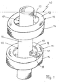
- the underwater transmission antenna 10 for a sonar system which is shown schematically in a perspective view in FIG. 1, is usually installed in a towed body, which is towed by a towing vehicle in the water.
- the hollow towed body is completely flooded with water.
- the outer skin of the towed body is made of a material (e.g., plastic) having an acoustic wave impedance equal to that of water.
- the wave resistance corresponds to the specific acoustic impedance of the material provided that the water can be assumed to be lossless, which is approximately the case.
- the underwater transmission antenna 10 has, in the example of Fig. 1, two electro-acoustic transducers 11 coaxially and vertically arranged one above the other at an axial distance from each other.
- the number of electroacoustic transducers 11 is not limited to two.
- Each of the two identical in construction, electro-acoustic transducer 11 has an annular body 12 which defines a cylindrical inner space 13.
- the annular body 12 is on its inside and outside with a protective jacket 14 made of acoustically transparent material, such as polyurethane or rubber.
- the detailed structure of the ring body 12 is shown and described for example in DE 19 528 881 C1.
- the ring body 12 consists of an aluminum tube, in which a plurality of axial slots is milled, are used in the pairwise oppositely polarized ceramic plates.
- the electroacoustic transducer 11 described here is characterized in that it is ensured by suitable measures that at least the center of the cylindrical inner space 13 has a characteristic impedance ⁇ ⁇ c, which is not equal to the characteristic impedance of water.
- This can be most easily realized with a pressure-resistant, cylindrical body 15, which is arranged coaxially with the ring body 12.
- the cylindrical body 15 has an outer diameter which is smaller than the inner diameter of the annular body 12 and protrudes in the axial direction over the two end faces of the annular body 12.
- the cylindrical body 15 may be formed as a hermetically sealed hollow body which is filled with a medium such as gas or liquid or with a solid or bulk material.
- a hollow body filled with air is used.
- the hollow body is made of metal or plastic.
- a solid solid or a porous material body, such as foam body can be used. In the latter case, the fabric body with a to provide closed-pore outer skin, so that the ingress of water and thus a change of the characteristic impedance of the cylindrical body 15 is prevented.
- the cylindrical body 15 of the individual transducers 11 in the case of training as a hollow cylinder to an elongated tube 16 or in the case of training as a solid solid or porous material body combined into a bar.
- the annular body 12 are held at an axial distance from each other on the tube 16 and on the rod.
- the holder has a plurality of mutually offset by equal circumferential angle to each other arranged holders 17 which are fixed on the one hand to the pipe 16 - or on the rod - and on the other hand on one of the end face of the ring body 12.
- a single holder 17 on the lower converter 11 is shown.
- a rubber block 18 is clamped.
- a foam element may also be used.
- the hermetically sealed tube 16 made of metal or plastic has been filled with air, a gas or a liquid or a bulk material, e.g. a granulate, or by filling with a solid a characteristic impedance ⁇ ⁇ c, which is not equal to the characteristic impedance of water.
- Fig. 3 In the diagram of Fig. 3 is the curve B of the transmission level L S of one of the two electroacoustic transducer 11 of Underwater transmission antenna 10 shown in Fig. 1 as a function of the voltage applied to the converter 11 operating voltage U S.
- the curve a shows the same function for the electro-acoustic transducer 11, in which the tube 16 or the cylindrical body 15 associated with the transducer 11 is removed and the cylindrical interior 13 is completely flooded. Both curves apply to the same water depth, ie the same water pressure. It can clearly be seen that with the electroacoustic transducer 11 according to the invention (curve b), the maximum achievable transmission level is higher by almost 3 dB.
Landscapes
- Physics & Mathematics (AREA)
- Engineering & Computer Science (AREA)
- Acoustics & Sound (AREA)
- Multimedia (AREA)
- Transducers For Ultrasonic Waves (AREA)
- Measurement Of Velocity Or Position Using Acoustic Or Ultrasonic Waves (AREA)
Description
- Die Erfindung betrifft einen elektroakustischen Wandler für Unterwassereinsatz der im Oberbegriff des Anspruchs 1 definierten Gattung.
- Ein solcher als Ringwandler bezeichneter, elektroakustischer Wandler ist beispielsweise aus der DE 19 528 881 C1 bekannt. Zur Realisierung einer akustischen Unterwasser-Antenne mit einem kleinen vertikalen Öffnungswinkel werden mehrere solche Ringwandler mit Vertikalabstand übereinander angeordnet. Eine Unterwasserantenne dieser Art findet beispielsweise als in Schleppkörpern integrierte Sendeantenne von Sonaranlagen Anwendung.
- Die mit einem solchen Ringwandler ins Wasser abgestrahlte akustische Leistung findet ihre Grenze mit Einsetzen der Kavitation in der Wandlerumgebung. Der Kavitationseinsatzpunkt ist wiederum abhängig von dem Wasserdruck am Wandlerort. Fig. 2 der Zeichnung zeigt die Abhängigkeit des Sendepegels LS eines Ringwandlers von der an dem Wandler angelegten Betriebsspannung US für verschiedene Werte des Unterwasserdrucks, wobei der Wasserdruck p von der unteren zur oberen Kurve hin zunimmt. Der Sendepegel LS einer Schallquelle, also des Sendewandlers, ist als der Schall- oder Schalldruckpegel im Abstand von Im vom Mittelpunkt der Schallquelle definiert. Das Ende jeder Kurve im Diagramm der Fig. 2 ist durch denjenigen Sendepegel festgelegt, bei dem Kavitation einsetzt. Deutlich ist zu erkennen, dass mit zunehmendem Wasserdruck p der Kavitationseinsatzpunkt zu höherem Sendepegel hin verschoben wird. Für den Sendewandler bedeutet dies, dass in größerer Wassertiefe mit einem größeren Sendepegel gearbeitet werden kann als bei geringerer Wassertiefe, bevor die Kavitationsgrenze erreicht wird.
- Ein bekannter elektroakustischer Wandler (H. Hachiya et al: "An Omnidirectional Transducer Design Attached with High Sound-Speed Material for Use in Deep Seas", Pros. of 9th Symposium on Ultrasonic Electronics, March 1989, Seite 57 bis 59) weist ein hohlzylindrisches Wanderelement (cylindrical transducer shell element) auf, an dessen Zylinderinnenwand ein Belag aus einem Material mit hoher Schallgeschwindigkeit, aus einem sog. Syntaktik-Schaum (syntactic foam), befestigt ist. Die Schallgeschwindigkeit des Schaums ist deutlich größer als die von Wasser, so dass es möglich ist, die Phase der einfallenden Schallwelle aufgrund der Differenz der Schallgeschwindigkeit zwischen Wasser und Schaum zu steuern. Der Wellenwiderstand oder die akustische Impedanz des Schaums ist so ausgelegt, dass dieser bzw. diese möglichst genau dem Wellenwiderstand von Wasser entspricht, damit die Sendeverluste im Grenzbereich Wasser/Schaum minimiert sind. Die geometrische Anordnung und die Form des Syntaktik-Schaums sind so gestaltet, dass der elektroakustischer Wandler in großer Wassertiefe eine omnidirektionale Richtcharakteristik aufweist.
- Der Erfindung liegt die Aufgabe zugrunde, einen elektroakustischen Wandler der eingangs genannten Art so zu verbessern, dass der von ihm ins Wasser abstrahlbare, vom Wasserdruck abhängige maximale Sendepegel, das ist der Sendepegel, bei dem gerade noch nicht Kavitation einsetzt, deutlich erhöht wird.
- Die Aufgabe ist bei einem elektroakustischen Wandler der im Oberbegriff des Anspruchs 1 angegebenen Gattung erfindungsgemäß durch die Merkmale im Kennzeichenteil des Anspruchs 1 gelöst.
- Der Erfindungsgemäße elektroakustische Wandler hat den Vorteil, dass durch die erfindungsgemäße Anordnung und Auslegung des druckfesten, zylindrischen Körpers im Zentrum des vom Ringkörper umschlossenen Innenraums bei vorgegebenem Wasserdruck der maximal erreichbare Sendepegel wesentlich größer ist als bei den herkömmlichen Wandlern, bei dem üblicherweise der Innenraum geflutet ist. Untersuchungen haben gezeigt, dass eine Steigerung des Sendepegels um bis zu 3 dB erzielt wird, ohne dass der Kavitationseinsatzpunkt erreicht wird. Damit ist es möglich, in Flachwassergebieten mit größerem Sendepegel und damit größerer Sendeleistung zu operieren. Große Sendeleistungen der Sendewandler bzw. der damit aufgebauten Sendeantennen lassen größere Detektionsreichweiten zu und verbesserte Empfangspegel erzielen, so dass die Ortungsergebnisse von Sonaranlagen deutlich verbessert werden können. Umgekehrt kann mit dem für eine bestimmte Sendeleistung optimierten Wandler die maximale Sendeleistung in einer deutlich geringeren Wassertiefe abgestrahlt werden, ohne dass Kavitation einsetzt. Damit wird der Einsatzbereich des Wandlers erheblich vergrößert, und es wird möglich, auch in Flachwassergebieten mit der Sonaranlage unterschiedlich tiefe Schallausbreitungskanäle zu nutzen.
- Zweckmäßige Ausführungsformen des erfindungsgemäßen elektroakustischen Wandlers mit vorteilhaften Weiterbildungen und Ausgestaltungen der Erfindung ergeben sich aus den weiteren Ansprüchen.
- Gemäß einer vorteilhaften Ausführungsform der Erfindung ist der zylindrische Körper hohl ausgebildet und mit Luft oder einem anderen Gas oder mit porösem Material oder mit Schüttgut gefüllt. Der Hohlkörper kann aus Stahl oder Kunststoff oder einem beliebigen anderen Material gefertigt werden. Alternativ kann der zylindrische Körper als massiver Körper aus einem Feststoff oder einem porösen Stoff ausgeführt werden. Im letzteren Fall muss der poröse Stoffkörper eine geschlossenporige Außenhaut besitzen, um das Eindringen von Wasser zu verhindern.
- Bei einer aus mehreren der erfindungsgemäßen Wandler zusammengesetzten Unterwasser-Sendeantenne ist gemäß einer vorteilhaften Ausführungsform der Erfindung der zylindrische Körper als langgestrecktes Rohr oder langgestreckter Stab ausgebildet, auf dem die Ringkörper der einzelnen Wandler im Axialabstand voneinander gehalten sind. Die Halterung erfolgt dabei körperschallentkoppelt, wozu in der Halterung zwischen Rohr oder Stab und den Ringkörpern Entkopplungselemente, z.B. Gummiklötze, angeordnet sind.
- Die Erfindung ist anhand eines in der Zeichnung dargestellten Ausführungsbeispiels im folgenden näher beschrieben. Es zeigen:
- Fig. 1
- eine perspektivische Darstellung einer aus zwei elektroakustischen Wandlern bestehenden Unterwasser-Sendeantenne, schematisch dargestellt,
- Fig. 2
- ein Diagramm des Sendepegel LS eines elektroakustischen Wandlers als Funktion der Wandlerspannung US bei verschiedenen Wasserdrücken,
- Fig. 3
- ein Diagramm des Sendepegels LS als Funktion der Wandlerspannung US für einen bekannten, herkömmlichen elektroakustischen Wandler (Kurve a) und des erfindungsgemäßen Wandlers (Kurve b) in der Sendeantenne gemäß Fig. 1.
- Die in Fig. 1 in perspektivischer Darstellung schematisch dargestellte Unterwasser-Sendeantenne 10 für eine Sonaranlage wird üblicherweise in einen Schleppkörper eingebaut, der von einen Schleppfahrzeug aus im Wasser nachgeschleppt wird. Der hohle Schleppkörper ist dabei vollständig mit Wasser geflutet. Die Außenhaut des Schleppkörpers ist aus einem Material gefertigt (z.B. Kunststoff), das einen akustischen Wellenwiderstand aufweist, der gleich dem von Wasser ist. Wie bekannt, entspricht der Wellenwiderstand der spezifischen Schallimpedanz des Materials unter der Voraussetzung, dass das Wasser als verlustfrei angenommen werden kann, was näherungsweise der Fall ist.
- Die Unterwasser-Sendeantenne 10 weist im Beispiel der Fig. 1, zwei elektroakustische Wandler 11 auf, die koaxial und vertikal übereinander mit Axialabstand voneinander angeordnet sind. Die Anzahl der elektroakustischen Wandler 11 ist nicht auf zwei beschränkt.
- Jeder der beiden im Aufbau identischen, elektroakustischen Wandler 11 besitzt einen Ringkörper 12, der einen zylindrischen Innenraum 13 umgrenzt. Der Ringkörper 12 ist auf seiner Innen- und Außenseite mit einem Schutzmantel 14 aus akustisch transparentem Material, z.B. Polyurethan oder Gummi, umgossen. Der detaillierte Aufbau des Ringkörpers 12 ist z.B. in der DE 19 528 881 C1 dargestellt und beschrieben. Im wesentlichen besteht der Ringkörper 12 aus einem Aluminiumrohr, in das eine Vielzahl von Axialschlitzen eingefräst ist, in die paarweise entgegengesetzt polarisierte Keramikplatten eingesetzt sind.
- Der hier beschriebene elektroakustische Wandler 11 zeichnet sich dadurch aus, dass durch geeignete Maßnahmen sichergestellt ist, dass zumindest das Zentrum des zylindrischen Innenraums 13 einen Wellenwiderstand ρ·c aufweist, der ungleich dem Wellenwiderstand von Wasser ist. Dies lässt sich am einfachsten mit einem druckfesten, zylindrischen Körper 15 realisieren, der koaxial zum Ringkörper 12 angeordnet ist. Der zylindrische Körper 15 hat dabei einen Außendurchmesser, der kleiner ist als der Innendurchmesser des Ringkörpers 12 und steht in Achsrichtung über die beiden Stirnseiten des Ringkörpers 12 vor. Durch den zwischen dem Außenmantel des zylindrischen Körpers 15 und dem Innenmantel des Ringkörpers 12 verbleibenden Ringspalt kann Wasser hindurchtreten und so für die Abführung von im Sendebetrieb anfallender Verlustwärme sorgen. Der zylindrische Körper 15 kann dabei als hermetisch geschlossener Hohlkörper ausgebildet sein, der mit einem Medium, wie Gas oder Flüssigkeit oder mit einem Fest- oder Schüttstoff gefüllt ist. Bevorzugt wird ein mit Luft gefüllter Hohlkörper verwendet. Der Hohlkörper wird aus Metall oder Kunststoff gefertigt. Anstelle des Hohlkörpers kann aber auch ein massiver Festkörper oder ein poröser Stoffkörper, z.B. Schaumstoffkörper, verwendet werden. Im letzteren Fall ist der Stoffkörper mit einer geschlossenporigen Außenhaut zu versehen, damit das Eindringen von Wasser und damit eine Veränderung des Wellenwiderstands des zylindrischen Körpers 15 verhindert wird.
- Im Ausführungsbeispiel der Unterwasser-Sendeantenne der Fig. 1 mit mindestens zwei elektroakustischen Wandlern 11 der beschriebenen Art sind die zylindrischen Körper 15 der einzelnen Wandler 11 im Falle der Ausbildung als Hohlzylinder zu einem langgestreckten Rohr 16 oder im Falle der Ausbildung als massiver Festkörper oder poröser Stoffkörper zu einem Stab zusammengefasst. Die Ringkörper 12 sind im Axialabstand voneinander an dem Rohr 16 bzw. an dem Stab gehalten. Die Halterung weist eine Mehrzahl von um gleiche Umfangswinkel zueinander versetzt angeordneten Haltern 17 auf, die einerseits an dem Rohr 16 - bzw. an dem Stab - und andererseits an einer der Stirnseite des Ringkörpers 12 befestigt sind. In Fig. 1 ist der Übersichtlichkeit halber nur ein einziger Halter 17 am unteren Wandler 11 dargestellt. Zur Körperschallentkopplung sind in der Halterung entsprechende Entkopplungselemente vorgesehen. Im Ausführungsbeispiel der Fig. 1 ist hierzu zwischen dem Halter 17 und der Stirnseite des Ringkörpers 12 ein Gummiklotz 18 eingespannt. Anstelle eines Gummiklotzes 18 kann auch ein Schaumstoffelement verwendet werden. Das hermetisch geschlossene, aus Metall oder Kunststoff gefertigte Rohr 16 hat durch Füllung mit Luft, einem Gas oder einer Flüssigkeit oder einem Schüttstoff, z.B. einem Granulat, oder durch Ausfüllung mit einem Feststoff einen Wellenwiderstand ρ·c, der ungleich dem Wellenwiderstand von Wasser ist.
- Im Diagramm der Fig. 3 ist mit Kurve b der Sendepegel LS von einem der beiden elektroakustischen Wandler 11 der Unterwasser-Sendeantenne 10 in Fig. 1 als Funktion der an den Wandler 11 gelegten Betriebsspannung US dargestellt. Die Kurve a zeigt die gleiche Funktion für den elektroakustischen Wandler 11, bei dem das Rohr 16 bzw. der dem Wandler 11 zugeordnete zylindrische Körper 15 entfernt und der zylindrische Innenraum 13 vollständig geflutet ist. Beide Kurven gelten für die gleiche Wassertiefe, d.h. den gleichen Wasserdruck. Deutlich ist zu sehen, dass mit dem elektroakustischen Wandler 11 gemäß der Erfindung (Kurve b) der maximal erreichbare Sendepegel um nahezu 3 dB höher liegt.
Claims (10)
- Elektroakustischer Wandler für Unterwassereinsatz mit einem einen zylindrischen Innenraum (13) einschließenden, akustisch wirksamen Ringkörper (12) und mit einem im Innenraum (13) koaxial zum Ringkörper (12) angeordneten, druckfesten, zylindrischen Körper (15), dadurch gekennzeichnet, dass der zylindrische Körper (15) stirnseitig geschlossen und mit einem gegenüber dem Innendurchmesser des Ringkörpers (12) kleineren Außendurchmesser so ausgebildet ist, dass zwischen dem Ringkörper (12) und dem zylindrischen Körper (15) ein Ringspalt verbleibt, und dass der zylindrische Körper (15) einen Wellenwiderstand (ρ·c) aufweist, der von dem Wellenwiderstand des Wassers abweicht.
- Wandler nach Anspruch 1, dadurch gekennzeichnet, dass der zylindrische Körper (15) ein poröser Stoffkörper, vorzugsweise Schaumstoffkörper, mit geschlossenporiger Außenhaut ist.
- Wandler nach Anspruch 1, dadurch gekennzeichnet, dass der zylindrische Körper (15) ein massiver Festkörper ist.
- Wandler nach Anspruch 1, dadurch gekennzeichnet, dass der zylindrische Körper (15) ein hermetisch geschlossener Hohlkörper ist, der mit einem Medium gefüllt ist.
- Wandler nach Anspruch 4, dadurch gekennzeichnet, dass das Medium ein Gas, vorzugsweise Luft, oder eine Flüssigkeit oder ein Fest- oder Schüttstoff ist.
- Wandler nach Anspruch 4 oder 5, dadurch gekennzeichnet, dass der Hohlkörper aus Metall oder Kunststoff gefertigt ist.
- Wandler nach einem der Ansprüche 1 bis 6, dadurch gekennzeichnet, dass der zylindrische Körper (15) in Achsrichtung über beide plane Stirnseiten des Ringkörpers (12) vorsteht.
- Wandler nach Anspruch 7, dadurch gekennzeichnet, dass der zylindrische Körper (15) ein langgestrecktes, hermetisch geschlossenes Rohr (16) oder ein langgestreckter Stab ist, an dem der Ringkörper (12) gehalten ist.
- Wandler nach Anspruch 8, dadurch gekennzeichnet, dass in der Halterung zwischen Rohr (16) bzw. Stab und Ringkörper (12) Elemente zur Körperschallentkopplung, z.B. Gummiklötze (18) angeordnet sind.
- Wandler nach Anspruch 8 oder 9, dadurch gekennzeichnet, dass auf dem Rohr (16) bzw. Stab mindestens ein zweiter Ringkörper (12) im Axialabstand vom ersten Ringkörper (12) angeordnet ist.
Applications Claiming Priority (2)
| Application Number | Priority Date | Filing Date | Title |
|---|---|---|---|
| DE19726442 | 1997-06-23 | ||
| DE1997126442 DE19726442C1 (de) | 1997-06-23 | 1997-06-23 | Elektroakustischer Wandler |
Publications (3)
| Publication Number | Publication Date |
|---|---|
| EP0887119A2 EP0887119A2 (de) | 1998-12-30 |
| EP0887119A3 EP0887119A3 (de) | 2001-09-12 |
| EP0887119B1 true EP0887119B1 (de) | 2006-09-06 |
Family
ID=7833276
Family Applications (1)
| Application Number | Title | Priority Date | Filing Date |
|---|---|---|---|
| EP19980111319 Expired - Lifetime EP0887119B1 (de) | 1997-06-23 | 1998-06-19 | Elektroakustischer Wandler für Unterwassereinsatz |
Country Status (2)
| Country | Link |
|---|---|
| EP (1) | EP0887119B1 (de) |
| DE (2) | DE19726442C1 (de) |
Families Citing this family (1)
| Publication number | Priority date | Publication date | Assignee | Title |
|---|---|---|---|---|
| DE102004038034A1 (de) * | 2004-08-05 | 2006-02-23 | Atlas Elektronik Gmbh | Elektroakustische Sendeantenne |
Family Cites Families (7)
| Publication number | Priority date | Publication date | Assignee | Title |
|---|---|---|---|---|
| US3177382A (en) * | 1961-01-25 | 1965-04-06 | Charles E Green | Mosaic construction for electroacoustical cylindrical transducers |
| US4764909A (en) * | 1969-08-07 | 1988-08-16 | The United States Of America As Represented By The Secretary Of The Navy | Hydrogen generator |
| US3961305A (en) * | 1975-02-14 | 1976-06-01 | The United States Of America As Represented By The Secretary Of The Navy | Fluid for filling sonar transducers |
| DE3444424A1 (de) * | 1984-12-06 | 1991-11-07 | Krupp Gmbh | Wandleranordnung fuer unterwasserantennen |
| US4774427A (en) * | 1987-05-08 | 1988-09-27 | Piezo Sona-Tool Corporation | Downhole oil well vibrating system |
| CA2074424A1 (en) * | 1992-07-22 | 1994-01-23 | Bryce L. Fanning | Acoustic gel |
| DE19528881C1 (de) * | 1995-08-05 | 1996-06-27 | Stn Atlas Elektronik Gmbh | Elektroakustischer Wandler |
-
1997
- 1997-06-23 DE DE1997126442 patent/DE19726442C1/de not_active Expired - Fee Related
-
1998
- 1998-06-19 DE DE59813710T patent/DE59813710D1/de not_active Expired - Lifetime
- 1998-06-19 EP EP19980111319 patent/EP0887119B1/de not_active Expired - Lifetime
Also Published As
| Publication number | Publication date |
|---|---|
| EP0887119A3 (de) | 2001-09-12 |
| DE59813710D1 (de) | 2006-10-19 |
| EP0887119A2 (de) | 1998-12-30 |
| DE19726442C1 (de) | 1999-01-28 |
Similar Documents
| Publication | Publication Date | Title |
|---|---|---|
| DE60005382T2 (de) | Breitbandiger unterwasser-schallwandler | |
| EP0654953B1 (de) | Elektroakustische Wandleranordnung | |
| DE1487569A1 (de) | Ultraschallwandler | |
| DE2539246A1 (de) | Piezoelektrischer wandler | |
| DE3437488A1 (de) | Schallsender | |
| DE3914143A1 (de) | Elektroakustischer Wandler mit Richtwirkung und einer dichten, zweiteiligen Schale | |
| DE69107675T2 (de) | Akustische Wandler. | |
| DE9109025U1 (de) | Generator zur Erzeugung akustischer Zugimpulse | |
| EP0441997B1 (de) | Medizinischer Ultraschall-Applikator zur Verwendung in einem von akustischen Stosswellen durchlaufenen Ausbreitungsmedium | |
| EP0905676B1 (de) | Sendeantenne für eine Sonaranlage | |
| DE19726442C1 (de) | Elektroakustischer Wandler | |
| DE19702347C2 (de) | Geräuschisolierendes Plattenelement | |
| DE2756069A1 (de) | Ultraschallwandler | |
| DE3620085A1 (de) | Rohrfoermiger elektroakustischer wandler | |
| DE3914141C2 (de) | Elektroakustischer Wandler mit einer flexiblen und dichten abstrahlenden Schale | |
| DE112009002445B4 (de) | Hydrophon und Hydrophonanordnung zum Durchführen von stereophonen Unterwasseraufnahmen | |
| EP2480346B1 (de) | Elektroakustischer wandler | |
| EP0500765B1 (de) | Resonanzschwinger | |
| EP1205260B1 (de) | Torpedosonar mit mehreren Wandlern | |
| EP1624445B1 (de) | Elektroakustische Sendeantenne | |
| DE19528881C1 (de) | Elektroakustischer Wandler | |
| DE8809252U1 (de) | Stoßwellenquelle zum Zertrümmern von Konkrementen | |
| DE4039408A1 (de) | Stosswellengenerator mit einem reflektor | |
| DE69602579T2 (de) | Sonarantenne mit empfindlichkeitsspitzen mindestens bei zwei frequenzen | |
| DE3743339A1 (de) | Elektroakustischer wandler, insbesondere fuer unterwasseranwendung |
Legal Events
| Date | Code | Title | Description |
|---|---|---|---|
| PUAI | Public reference made under article 153(3) epc to a published international application that has entered the european phase |
Free format text: ORIGINAL CODE: 0009012 |
|
| AK | Designated contracting states |
Kind code of ref document: A2 Designated state(s): AT BE CH CY DE DK ES FI FR GB GR IE IT LI LU MC NL PT SE Kind code of ref document: A2 Designated state(s): DE FR GB IT |
|
| AX | Request for extension of the european patent |
Free format text: AL;LT;LV;MK;RO;SI |
|
| PUAL | Search report despatched |
Free format text: ORIGINAL CODE: 0009013 |
|
| AK | Designated contracting states |
Kind code of ref document: A3 Designated state(s): AT BE CH CY DE DK ES FI FR GB GR IE IT LI LU MC NL PT SE |
|
| AX | Request for extension of the european patent |
Free format text: AL;LT;LV;MK;RO;SI |
|
| 17P | Request for examination filed |
Effective date: 20011006 |
|
| AKX | Designation fees paid |
Free format text: DE FR GB IT |
|
| RBV | Designated contracting states (corrected) |
Designated state(s): FR GB IT NL |
|
| REG | Reference to a national code |
Ref country code: DE Ref legal event code: 8566 |
|
| RAP1 | Party data changed (applicant data changed or rights of an application transferred) |
Owner name: ATLAS ELEKTRONIK GMBH |
|
| GRAP | Despatch of communication of intention to grant a patent |
Free format text: ORIGINAL CODE: EPIDOSNIGR1 |
|
| GRAS | Grant fee paid |
Free format text: ORIGINAL CODE: EPIDOSNIGR3 |
|
| GRAA | (expected) grant |
Free format text: ORIGINAL CODE: 0009210 |
|
| RBV | Designated contracting states (corrected) |
Designated state(s): DE FR GB IT NL |
|
| AK | Designated contracting states |
Kind code of ref document: B1 Designated state(s): DE FR GB IT NL |
|
| PG25 | Lapsed in a contracting state [announced via postgrant information from national office to epo] |
Ref country code: IT Free format text: LAPSE BECAUSE OF FAILURE TO SUBMIT A TRANSLATION OF THE DESCRIPTION OR TO PAY THE FEE WITHIN THE PRESCRIBED TIME-LIMIT;WARNING: LAPSES OF ITALIAN PATENTS WITH EFFECTIVE DATE BEFORE 2007 MAY HAVE OCCURRED AT ANY TIME BEFORE 2007. THE CORRECT EFFECTIVE DATE MAY BE DIFFERENT FROM THE ONE RECORDED. Effective date: 20060906 |
|
| REG | Reference to a national code |
Ref country code: GB Ref legal event code: FG4D Free format text: NOT ENGLISH |
|
| GBT | Gb: translation of ep patent filed (gb section 77(6)(a)/1977) |
Effective date: 20060923 |
|
| REF | Corresponds to: |
Ref document number: 59813710 Country of ref document: DE Date of ref document: 20061019 Kind code of ref document: P |
|
| ET | Fr: translation filed | ||
| PLBE | No opposition filed within time limit |
Free format text: ORIGINAL CODE: 0009261 |
|
| STAA | Information on the status of an ep patent application or granted ep patent |
Free format text: STATUS: NO OPPOSITION FILED WITHIN TIME LIMIT |
|
| 26N | No opposition filed |
Effective date: 20070607 |
|
| PGFP | Annual fee paid to national office [announced via postgrant information from national office to epo] |
Ref country code: NL Payment date: 20110621 Year of fee payment: 14 |
|
| REG | Reference to a national code |
Ref country code: NL Ref legal event code: V1 Effective date: 20130101 |
|
| PG25 | Lapsed in a contracting state [announced via postgrant information from national office to epo] |
Ref country code: NL Free format text: LAPSE BECAUSE OF NON-PAYMENT OF DUE FEES Effective date: 20130101 |
|
| REG | Reference to a national code |
Ref country code: DE Ref legal event code: R082 Ref document number: 59813710 Country of ref document: DE |
|
| REG | Reference to a national code |
Ref country code: FR Ref legal event code: PLFP Year of fee payment: 19 |
|
| PGFP | Annual fee paid to national office [announced via postgrant information from national office to epo] |
Ref country code: GB Payment date: 20160621 Year of fee payment: 19 Ref country code: DE Payment date: 20160621 Year of fee payment: 19 |
|
| PGFP | Annual fee paid to national office [announced via postgrant information from national office to epo] |
Ref country code: FR Payment date: 20160627 Year of fee payment: 19 |
|
| PGFP | Annual fee paid to national office [announced via postgrant information from national office to epo] |
Ref country code: IT Payment date: 20160628 Year of fee payment: 19 |
|
| REG | Reference to a national code |
Ref country code: DE Ref legal event code: R119 Ref document number: 59813710 Country of ref document: DE |
|
| GBPC | Gb: european patent ceased through non-payment of renewal fee |
Effective date: 20170619 |
|
| REG | Reference to a national code |
Ref country code: FR Ref legal event code: ST Effective date: 20180228 |
|
| PG25 | Lapsed in a contracting state [announced via postgrant information from national office to epo] |
Ref country code: GB Free format text: LAPSE BECAUSE OF NON-PAYMENT OF DUE FEES Effective date: 20170619 Ref country code: DE Free format text: LAPSE BECAUSE OF NON-PAYMENT OF DUE FEES Effective date: 20180103 |
|
| PG25 | Lapsed in a contracting state [announced via postgrant information from national office to epo] |
Ref country code: FR Free format text: LAPSE BECAUSE OF NON-PAYMENT OF DUE FEES Effective date: 20170630 Ref country code: IT Free format text: LAPSE BECAUSE OF NON-PAYMENT OF DUE FEES Effective date: 20170619 |