EP0886994B1 - Schaltschrank mit schranktüre und kühlgerät - Google Patents
Schaltschrank mit schranktüre und kühlgerät Download PDFInfo
- Publication number
- EP0886994B1 EP0886994B1 EP97903267A EP97903267A EP0886994B1 EP 0886994 B1 EP0886994 B1 EP 0886994B1 EP 97903267 A EP97903267 A EP 97903267A EP 97903267 A EP97903267 A EP 97903267A EP 0886994 B1 EP0886994 B1 EP 0886994B1
- Authority
- EP
- European Patent Office
- Prior art keywords
- carrier plate
- external circuit
- cooler
- ventilation chambers
- accommodation area
- Prior art date
- Legal status (The legal status is an assumption and is not a legal conclusion. Google has not performed a legal analysis and makes no representation as to the accuracy of the status listed.)
- Expired - Lifetime
Links
- 238000009423 ventilation Methods 0.000 claims description 23
- 230000000712 assembly Effects 0.000 claims description 20
- 238000000429 assembly Methods 0.000 claims description 20
- 230000004308 accommodation Effects 0.000 claims 11
- 238000001816 cooling Methods 0.000 description 19
- 238000007789 sealing Methods 0.000 description 5
- 238000005192 partition Methods 0.000 description 2
- 230000005494 condensation Effects 0.000 description 1
- 238000009833 condensation Methods 0.000 description 1
- 238000010276 construction Methods 0.000 description 1
- 230000007613 environmental effect Effects 0.000 description 1
- 238000009434 installation Methods 0.000 description 1
Images
Classifications
-
- H—ELECTRICITY
- H05—ELECTRIC TECHNIQUES NOT OTHERWISE PROVIDED FOR
- H05K—PRINTED CIRCUITS; CASINGS OR CONSTRUCTIONAL DETAILS OF ELECTRIC APPARATUS; MANUFACTURE OF ASSEMBLAGES OF ELECTRICAL COMPONENTS
- H05K7/00—Constructional details common to different types of electric apparatus
- H05K7/20—Modifications to facilitate cooling, ventilating, or heating
-
- H—ELECTRICITY
- H05—ELECTRIC TECHNIQUES NOT OTHERWISE PROVIDED FOR
- H05K—PRINTED CIRCUITS; CASINGS OR CONSTRUCTIONAL DETAILS OF ELECTRIC APPARATUS; MANUFACTURE OF ASSEMBLAGES OF ELECTRICAL COMPONENTS
- H05K7/00—Constructional details common to different types of electric apparatus
- H05K7/20—Modifications to facilitate cooling, ventilating, or heating
- H05K7/20536—Modifications to facilitate cooling, ventilating, or heating for racks or cabinets of standardised dimensions, e.g. electronic racks for aircraft or telecommunication equipment
- H05K7/20609—Air circulating in closed loop within cabinets wherein heat is removed through air-to-liquid heat-exchanger
-
- H—ELECTRICITY
- H02—GENERATION; CONVERSION OR DISTRIBUTION OF ELECTRIC POWER
- H02B—BOARDS, SUBSTATIONS OR SWITCHING ARRANGEMENTS FOR THE SUPPLY OR DISTRIBUTION OF ELECTRIC POWER
- H02B1/00—Frameworks, boards, panels, desks, casings; Details of substations or switching arrangements
- H02B1/56—Cooling; Ventilation
- H02B1/565—Cooling; Ventilation for cabinets
Definitions
- the invention relates to a control cabinet with a closable by means of a cabinet door Cabinet body and a cooling device with a fan and evaporator Internal circuit and a compressor, condenser and fan External circuit, the cooling device with a trough-shaped, on the cabinet body articulated and closable on this outer housing part and with one of these covering support plate is provided, the of the outer housing part and the Carrier plate enclosed space form an upper and a lower receiving space, and wherein the carrier plate in the region of the upper receiving space has air intake openings and underneath has an air outlet opening for the internal circuit.
- Such a configuration of a control cabinet is known from US 3,559,728.
- the cooling device has a trough-shaped outer housing part which is divided into two chambers.
- Each of the chambers takes cooling device assemblies of the cooling circuit.
- the first chamber stands in with the surroundings Connection, while the second chamber faces the interior of the control cabinet is.
- a cooling device is known from FR-A-2 085 219, which is designed as a wall-mounted device is. As such, it protrudes and shrinks in the interior of the control cabinet thus the installation volume of the control cabinet.
- a control cabinet is also known a control system for environmental conditions in the door of the control cabinet is installed.
- the door has two fans and a heat exchanger. The Fresh air is drawn in and discharged from the front.
- a control cabinet of the type mentioned above to design that the refrigerator like a cabinet door with the cabinet body can be connected, in particular the two types of attack - left or posted on the right - can be taken into account.
- cooling device as Cabinet door is designed that in the open upward, upper receiving space Cooling unit assemblies of the inner circuit arranged, attached to the support plate and to this are hermetically covered that in the bottom open, lower Recording room arranged the cooling device assemblies of the external circuit and with the Carrier plate are connected, and that fresh air for the external circuit via the open lower side of the lower receiving space sucked in via the cooling unit assemblies of the external circuit, in the lower area of the upper receiving space initiated and derived on the open side of the upper recording space.
- the outer housing part practically replaces the cabinet door and is like one on Cabinet body attachable.
- the carrier plate carries all components of the cooling unit and is connectable to the housing outer part, the attachment being the type of attachment of the Housing outer part on the cabinet body can take into account the arrangement of the Reach the cooling unit assemblies regardless of how the cooling unit is attached to be able to. By dividing it into an upper and a lower recording room and the distribution of the components of the inner and outer circuit is with the hermetic coverage of the assemblies of the inner trial run a clear Decoupling of the two circuits is achieved, so that no condensation in the Shadow cabinet can reach.
- the construction of the cooling device is simple, as all Assemblies can be attached to the carrier plate.
- the hermetic covering of the assemblies of the internal circuit is based on a Design achieved in that the cooling device assemblies of the inner circuit are covered by a cover that matches the inside of the cabinet opposite sides of the support plate is connected.
- the outer housing part to the on the vertical sides of the ventilation chambers which are partitioned off by dividers, shows that Housing outer part and the ventilation chambers by means of partitions according to the upper and lower receiving space are divided, and that the dividers of Ventilation chambers in the upper receiving space air inlet openings and in the lower Recording space have air outlet openings, then the air duct of the External circuit can be performed over both recording rooms.
- a fastening possibility for the carrier plate on the outer housing part is thereby created that the ventilation chambers parallel to the support plate mounting sections have that with mounting receptacles for mounting the support plate in two positions are rotated by 180 °. Thereby the distribution and arrangement bears the mounting brackets the two types of attachment of the refrigerator.
- the outer part of the housing can be hinged to the cabinet body in positions rotated by 180 ° become.
- the carrier plate can always be connected to the housing outer part in such a way that the Recording room with the internal circuit above.
- the outer housing part has trapezoidal cross-section, and that the ventilation chambers divided therein enclose a right-angled-triangular cross-section.
- the trapezoidal shape of the The outer part of the housing creates a visually appealing design of the control cabinet and the ventilation chambers stiffen the outer housing part.
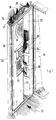
- FIG. 1 Of the cabinet body 10 in Fig. 1 only the part of the front is shown on which the Cooling device is hinged like a closet door.
- the refrigerator has a trough-like Outer housing part 20 with a trapezoidal cross-section, which in the closed position Outer contour of the control cabinet completed.
- the linkage and the locking of the housing outer part 20 on the cabinet body takes place in a manner known per se known hinge and locking elements. Because this is for the present invention are not important, there is no need to go into details. This Elements are therefore not shown in the drawings.
- the open side of the housing outer part facing the interior of the control cabinet 20 is closed with a carrier plate 30.
- This carrier plate 30 encloses with the housing outer part 20, a space having an upper receiving space 25 and forms a lower receiving space 27.
- the division is preferably made about halfway up the refrigerator used as a cabinet door.
- the upper Receiving space 25 is upward and the lower receiving space 27 is downward open.
- On the side facing away from the interior of the control cabinet of the carrier plate 30 are the assemblies of the inner circuit in the upper receiving space 25 of the cooling device, a fan 40 and an evaporator 41 are arranged and on the Carrier plate 30 attached.
- the assemblies of the external circuit are on the support plate 30, a compressor 50, a condenser 51 and a fan 52 are arranged and attached.
- the fan 52 of the external circuit sucks fresh air into the lower receiving space 27.
- separating plates 23 are used and 24 ventilation chambers 21 and 22 divided by means of partitions 26 accordingly of the upper and lower receiving space 25 and 26 are divided accordingly.
- the sucked-in fresh air flow 33 not only reaches the lower receiving space 27, but also in the lower parts of the ventilation chambers 21 and 22. These partial flows occur through the air outlet openings 28 in the lower receiving space 27. Der Fresh air flow 33 sweeps over the assemblies 50, 51 and 52 of the external circuit in the lower receiving space 27.
- the fan 52 of the external circuit guides the fresh air flow in the upper receiving space 25 and via the air inlet openings 29 in the Ventilation chambers 21 and 22, as shown by arrows 34 and 35.
- the fresh air flow occurs on the open, upper sides of the upper receiving space 25 and the ventilation chambers 21 and 22 as shown by arrows 36.
- the ventilation chambers 21 and 22 are closed and have a rectangular-triangular shape or a pentagonal cross section. Parallel to the carrier plate 30 Sections of the ventilation chambers 21 and 22 serve as a mounting surface for the Carrier plate 30, sealing elements being used as an intermediate layer can be. In addition, the carrier plate 30 leaves the edges of the housing outer part 20 marginal areas free, which are required for sealing to the cabinet body Wear sealing elements or are designed as sealing webs, which with Work the sealing elements on the cabinet body 10 together.
- the mounting surfaces for the carrier plate 30 are with mounting receptacles provided that attaching the support plate 30 in two positions rotated by 180 ° allow on the housing outer part 20.
- the outer housing part 20 can then be left or be hinged to the right on the open front of the cabinet body 10.
- the Assemblies 40 and 41 of the inner circuit and assemblies 50, 51 and 52 of External circuit can always be used in the orientation shown in Fig. 1 come.
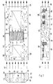
- FIG. 2 shows three schematic, perpendicular to each other Sections or views of the course of the fresh air in the external circuit shown.
- the Fan 52 is for sucking the fresh air 33 into the lower receiving space 25 and the divided lower areas of the ventilation chambers 21 and 22 are responsible.
- the part of the fresh air drawn in, which via the ventilation chambers 21 and 22nd is sucked in through the air outlet openings 28 of the separating plates 23 and 24 in the lower receiving space 27 a.
- the Fresh air passed through the condenser 51 and then passes through the heated free space of the upper receiving space 25, which is not through the cover 42 is occupied, as the arrows 34 show.
Landscapes
- Engineering & Computer Science (AREA)
- Physics & Mathematics (AREA)
- Thermal Sciences (AREA)
- Microelectronics & Electronic Packaging (AREA)
- Aviation & Aerospace Engineering (AREA)
- Power Engineering (AREA)
- Devices That Are Associated With Refrigeration Equipment (AREA)
- Cooling Or The Like Of Electrical Apparatus (AREA)
Description
- Fig. 1
- eine Teilansicht in Perspektive, die das am Schrankkorpus angelenkte Kühlgerät in der Offenstellung erkennen läßt, und
- Fig. 2
- schematisch drei senkrecht zueinander stehende Schnitte und Ansichten, denen die Verteilung und Anordnung der Baugruppen des Kühlgerätes zu entnehmen ist.
Claims (8)
- Schaltschrank mit einem mittels Schranktüre verschließbaren Schrank-korpus und einem Kühlgerät mit einem aus Lüfter und Verdampfer bestehenden Innenkreislauf und einem aus Kompressor, Verflüssiger und Lüfter bestehenden Außenkreislauf, wobei das Kühlgerät mit einem wannenförmigen, am Schrankkorpus anlenkbaren und an diesem verschließbaren Gehäuseaußenteil und mit einer dieses abdeckenden Trägerplatte versehen ist, wobei der von dem Gehäuseaußenteil und der Trägerplatte umschlossene Raum einen oberen und einen unteren Aufnahmeraum bilden, und wobei die Trägerplatte im Bereich des oberen Aufnahmeraumes Luftansaugöffnungen und darunter eine Luftaustrittsöffnung für den Innenkreislauf aufweist, wobeidas Kühlgerät als Schranktüre ausgebildet ist, wobei in dem nach oben offenen, oberen Aufnahmeraum die Kühlgerät-Baugruppen (40,41) des Innenkreislaufes angeordnet, auf der Trägerplatte (30) befestigt und zu dieser hermetisch abgedeckt sind,wobei in dem nach unten offenen, unteren Aufnahmeraum (27) die Kühlgeräte-Baugruppen (50,51,52) des Außenkreislaufes angeordnet und mit der Trägerplatte (30) verbunden sind, undwobei Frischluft (33) für den Außenkreislauf über die offene untere Seite des unteren Aufnahmeraumes (27) angesaugt, über die Kühlgeräte-Baugruppen (50,51,52) des Außenkreislaufes geleitet, in den unteren Bereich des oberen Aufnahmeraumes (25) eingeleitet und an der offenen oberen Seite des oberen Aufnahmeraumes (25) abgeleitet wird (36).
- Schaltschrank nach Anspruch 1,
dadurch gekennzeichnet,
daß die Kühlgerät-Baugruppen (40,41) des Innenkreislaufes mittels einer Abdeckhaube (42) abgedeckt sind, die mit der dem Schrankinnenraum abgekehrten Seite der Trägerplatte (30) verbunden ist. - Schaltschrank nach Anspruch 1 oder 2,
dadurch gekennzeichnet,daß das Gehäuseaußenteil (20) an den vertikalen Seiten mittels Trennbleche (23,24) abgeteilte Lüftungskammern (21,22) aufweist,daß das Gehäuseaußenteil (20) und die Lüftungskammern (21,22) mittels Trennwänden (26) in dem oberen und unteren Aufnahmeraum (25,27) unterteilt sind, unddaß die Trennbleche (23,24) der Lüftungskammern (21,22) im oberen Aufnahmeraum (25) Lufteintrittsdurchbrüche (29) und im unteren Aufnahmeraum (27) Luftaustrittsdurchbrüche (28) aufweisen. - Schaltschrank nach einem der Ansprüche 1 bis 3,
dadurch gekennzeichnet,
daß die Lüftungskammern (21,22) zur Trägerplatte (30) parallele Befestigungsabschnitte aufweisen, die mit Befestigungsaufnahmen für eine Befestigung der Trägerplatte (30) in zwei um 180° verdrehten Stellungen versehen sind. - Schaltschrank nach einem der Ansprüche 1 bis 4,
dadurch gekennzeichnet,
daß das Gehäuseaußenteil (20) einen trapezförmigen Querschnitt aufweist, und daß die darin abgeteilten Lüftungskammern (21,22) einen rechtwinklig-dreieckförmigen Querschnitt umschließen. - Schaltschrank nach Anspruch 1,
dadurch gekennzeichnet,
daß der Verflüssiger (51) des Außenkreislaufes den oberen und den unteren Aufnahmeraum (25 und 27) abteilt. - Schaltschrank nach einem der Ansprüche 1 bis 6,
dadurch gekennzeichnet,
daß die Trennwände (26) in den Lüftungskammern (21,22) im Bereich des Verflüssigers (51) des Außenkreislaufes angeordnet sind. - Schaltschrank nach einem der Ansprüche 1 bis 7,
dadurch gekennzeichnet,
daß der Lüfter (52) des Außenkreislaufes unmittelbar über dem Verflüssiger (51) des Außenkreislaufes, jedoch unterhalb der Lufteintrittsdurchbrüche (29) in den Trennblechen (23,24) der Lüftungskammern (21,22) angeordnet ist.
Applications Claiming Priority (3)
| Application Number | Priority Date | Filing Date | Title |
|---|---|---|---|
| DE19609794A DE19609794C1 (de) | 1996-03-13 | 1996-03-13 | Schaltschrank mit Schranktüre und Kühlgerät |
| DE19609794 | 1996-03-13 | ||
| PCT/EP1997/000658 WO1997034455A1 (de) | 1996-03-13 | 1997-02-13 | Schaltschrank mit schranktüre und kühlgerät |
Publications (2)
| Publication Number | Publication Date |
|---|---|
| EP0886994A1 EP0886994A1 (de) | 1998-12-30 |
| EP0886994B1 true EP0886994B1 (de) | 1999-08-11 |
Family
ID=7788118
Family Applications (1)
| Application Number | Title | Priority Date | Filing Date |
|---|---|---|---|
| EP97903267A Expired - Lifetime EP0886994B1 (de) | 1996-03-13 | 1997-02-13 | Schaltschrank mit schranktüre und kühlgerät |
Country Status (9)
| Country | Link |
|---|---|
| US (1) | US6134109A (de) |
| EP (1) | EP0886994B1 (de) |
| JP (1) | JP3295093B2 (de) |
| KR (1) | KR100299406B1 (de) |
| BR (1) | BR9708040A (de) |
| DE (1) | DE19609794C1 (de) |
| ES (1) | ES2137048T3 (de) |
| TW (1) | TW361062B (de) |
| WO (1) | WO1997034455A1 (de) |
Families Citing this family (35)
| Publication number | Priority date | Publication date | Assignee | Title |
|---|---|---|---|---|
| DE19804901C2 (de) * | 1998-02-07 | 2003-04-17 | Rittal Gmbh & Co Kg | Schaltschrank |
| DE19804905C2 (de) * | 1998-02-07 | 2003-03-06 | Rittal Gmbh & Co Kg | Schaltschrank |
| DE19804900C2 (de) * | 1998-02-07 | 2003-04-30 | Rittal Gmbh & Co Kg | Schaltschrank |
| DE19809997C1 (de) * | 1998-03-07 | 2000-01-13 | Loh Kg Rittal Werk | Schaltschrank |
| GB2344939B (en) * | 1998-12-15 | 2000-11-15 | Shin Jiuh Corp | Power supply |
| DE19917289C1 (de) * | 1999-04-16 | 2000-10-19 | Loh Kg Rittal Werk | Schaltschrank |
| EP1207732A3 (de) | 2000-11-11 | 2004-07-21 | Rittal GmbH & Co. KG | Schaltschrank mit einer Klimatisierungseinrichtung |
| US6983566B2 (en) * | 2001-05-23 | 2006-01-10 | Upstate Systems Tec. Inc. | Door and frame with peripheral venting for electronic component cabinet |
| DE10156701B4 (de) * | 2001-11-17 | 2005-07-07 | Rittal Gmbh & Co. Kg | Schwingungsgedämpfte Befestigung eines Kühlgerätes an einem Verkleidungselement eines Schaltschrankes |
| US6889752B2 (en) * | 2002-07-11 | 2005-05-10 | Avaya Technology Corp. | Systems and methods for weatherproof cabinets with multiple compartment cooling |
| DE10325929A1 (de) * | 2003-06-07 | 2005-01-05 | Rittal Gmbh & Co. Kg | Kühlanlage für einen oder mehrere Schaltschränke |
| DE10352023B4 (de) * | 2003-11-07 | 2010-12-30 | Rittal Rcs Communication Systems Gmbh & Co. Kg | Klimatisierungsvorrichtung |
| US7003971B2 (en) * | 2004-04-12 | 2006-02-28 | York International Corporation | Electronic component cooling system for an air-cooled chiller |
| EP2302172A1 (de) | 2004-11-12 | 2011-03-30 | Board of Trustees of Michigan State University | Maschine mit einem elektromagnetischen gewebten Rotor sowie Herstellungsverfahren |
| US7555891B2 (en) | 2004-11-12 | 2009-07-07 | Board Of Trustees Of Michigan State University | Wave rotor apparatus |
| DE102005005296B3 (de) * | 2005-02-04 | 2006-05-18 | Knürr AG | Anordnung zur Kühlung von elektronischen Moduleinheiten in Geräte- und Netzwerkschränken |
| DE202005018284U1 (de) * | 2005-04-08 | 2006-02-02 | Rittal Gmbh & Co. Kg | Kühleinheit |
| US7724516B2 (en) * | 2005-08-26 | 2010-05-25 | The Boeing Company | Cooling enclosure for maintaining commercial-off-the-shelf (COTS) equipment in vehicles |
| TWI263022B (en) * | 2005-09-06 | 2006-10-01 | Jian-Jung Jang | Air circulation device |
| US7447026B2 (en) * | 2006-08-31 | 2008-11-04 | Hewlett-Packard Development Company, L.P. | System for hot swapping heat exchangers |
| US8141621B2 (en) * | 2008-12-11 | 2012-03-27 | International Business Machines Corporation | Apparatus and method for providing in situ cooling of computer data centers during service calls |
| JP5243614B2 (ja) * | 2009-06-26 | 2013-07-24 | 株式会社日立製作所 | ストレージ装置、ストレージ装置の記憶制御部、記憶制御部用筐体 |
| EP2490517A1 (de) * | 2009-10-16 | 2012-08-22 | Fujitsu Limited | Elektronische vorrichtung und gehäuse für die elektronische vorrichtung |
| WO2012116285A2 (en) | 2011-02-25 | 2012-08-30 | Board Of Trustees Of Michigan State University | Wave disc engine apparatus |
| CN102269134A (zh) * | 2011-06-08 | 2011-12-07 | 新乡豫新车辆换热设备股份有限公司 | 一种风能发电机组水冷系统的自然冷却换热装置 |
| US9016352B2 (en) | 2012-05-21 | 2015-04-28 | Calvary Applied Technologies, LLC | Apparatus and methods for cooling rejected heat from server racks |
| US8436246B1 (en) | 2012-10-19 | 2013-05-07 | Calvary Applied Technologies, LLC | Refrigerant line electrical ground isolation device for data center cooling applications |
| EP2762796A1 (de) * | 2013-02-04 | 2014-08-06 | ABB Oy | Kühlanordnung |
| US10193430B2 (en) | 2013-03-15 | 2019-01-29 | Board Of Trustees Of Michigan State University | Electromagnetic device having discrete wires |
| US9157670B2 (en) * | 2013-10-25 | 2015-10-13 | Kooltronic, Inc. | Hazardous location heat transfer unit |
| US10004165B1 (en) * | 2017-03-10 | 2018-06-19 | Amazon Technnologies, Inc. | Self-filling humidity control device for equipment racks |
| US20190107296A1 (en) | 2017-10-10 | 2019-04-11 | Trane International Inc. | Modular heat pump system |
| CN111525420A (zh) * | 2020-05-11 | 2020-08-11 | 江苏科技大学 | 一种用于开关柜的可移动散热装置 |
| EP4075936A1 (de) * | 2021-04-12 | 2022-10-19 | Hoffman Enclosures, Inc. | Klimaanlage für abgedichtete gehäuse |
| DE102021128023A1 (de) | 2021-10-27 | 2023-04-27 | Meinrad Ruf | Paneel mit einem Lüftungsgerät |
Family Cites Families (12)
| Publication number | Priority date | Publication date | Assignee | Title |
|---|---|---|---|---|
| US3559728A (en) * | 1968-11-29 | 1971-02-02 | Kooltronic Fan Co | Electronic equipment rack temperature control |
| FR2085219A1 (en) * | 1970-02-17 | 1971-12-24 | Telemecanique Electrique | Counter-current plate heater exchanger - for cooling cabinets partic electric cabinets |
| US3871188A (en) * | 1973-09-07 | 1975-03-18 | Thermo King Corp | Demountable transportation refrigeration unit |
| US4013120A (en) * | 1974-01-21 | 1977-03-22 | Martin Rheinheimer | Air conditioner |
| DE3136226C2 (de) * | 1981-09-12 | 1991-02-14 | Ing. Rolf Seifert electronic GmbH, 5828 Ennepetal | Klimagerät |
| US4424684A (en) * | 1982-01-05 | 1984-01-10 | Thermo King Corporation | Condenser section for container refrigeration unit |
| DE3815619A1 (de) * | 1988-05-07 | 1989-11-16 | Sueddeutsche Kuehler Behr | Einrichtung zur kuehlung elektrischer schaltschraenke |
| US5036677A (en) * | 1989-09-07 | 1991-08-06 | Mclean Midwest Corporation | Air conditioner having improved structure for cooling electronics |
| US5187950A (en) * | 1992-02-28 | 1993-02-23 | Weldon Mark P | Door mounted cooling apparatus |
| GB2277767B (en) * | 1993-05-06 | 1996-07-10 | Nokia Telecommunications Oy | Telecommunications base stations |
| US5467250A (en) * | 1994-03-21 | 1995-11-14 | Hubbell Incorporated | Electrical cabinet with door-mounted heat exchanger |
| US5657641A (en) * | 1995-09-13 | 1997-08-19 | Kooltronic, Inc. | Panel mounted cooling system |
-
1996
- 1996-03-13 DE DE19609794A patent/DE19609794C1/de not_active Expired - Lifetime
-
1997
- 1997-02-13 WO PCT/EP1997/000658 patent/WO1997034455A1/de not_active Ceased
- 1997-02-13 ES ES97903267T patent/ES2137048T3/es not_active Expired - Lifetime
- 1997-02-13 JP JP53222397A patent/JP3295093B2/ja not_active Expired - Fee Related
- 1997-02-13 BR BR9708040A patent/BR9708040A/pt not_active IP Right Cessation
- 1997-02-13 EP EP97903267A patent/EP0886994B1/de not_active Expired - Lifetime
- 1997-02-13 KR KR1019980707212A patent/KR100299406B1/ko not_active Expired - Fee Related
- 1997-02-13 US US09/142,633 patent/US6134109A/en not_active Expired - Lifetime
- 1997-03-13 TW TW086103100A patent/TW361062B/zh not_active IP Right Cessation
Also Published As
| Publication number | Publication date |
|---|---|
| ES2137048T3 (es) | 1999-12-01 |
| DE19609794C1 (de) | 1997-09-18 |
| KR100299406B1 (ko) | 2001-09-06 |
| JPH11511597A (ja) | 1999-10-05 |
| TW361062B (en) | 1999-06-11 |
| US6134109A (en) | 2000-10-17 |
| KR19990087740A (ko) | 1999-12-27 |
| JP3295093B2 (ja) | 2002-06-24 |
| BR9708040A (pt) | 1999-07-27 |
| EP0886994A1 (de) | 1998-12-30 |
| WO1997034455A1 (de) | 1997-09-18 |
Similar Documents
| Publication | Publication Date | Title |
|---|---|---|
| DE19609794C1 (de) | Schaltschrank mit Schranktüre und Kühlgerät | |
| DE10136457B4 (de) | Schaltschrank mit einer an der Frontseite angebrachten Schranktür und einer als Schranktür ausgebildeten Rückwand | |
| EP0886995B1 (de) | Kühlgerät zum anbau an die rückwand, seitenwand oder tür eines schaltschrankes | |
| EP1053583B1 (de) | Schaltschrank mit einer klimatisierungs-einrichtung | |
| EP0691071B1 (de) | Belüftungssystem für schränke mit stark wärmeerzeugenden elektronischen funktionseinheiten | |
| EP0886899B1 (de) | Modularer gehäuseaufbau | |
| DE19804904C1 (de) | Schaltschrank mit Einrichtungen zum Kühlen der Innenraum-Warmluft | |
| EP1155269A1 (de) | Kältegerät für den einbau in eine möbelnische | |
| DE19804902A1 (de) | Schaltschrank | |
| DE19804906A1 (de) | Lüfter zum Anbau an ein Wandelement eines Schaltschrankes | |
| DE19737531C2 (de) | Wärmetauscherbausatz und Klimatisierungsmeßgerät | |
| EP0913015B1 (de) | Kühlgerät zum aufbau auf einem schaltschrank | |
| EP1367877B1 (de) | Klimatisierungssystem, insbesondere für Schaltschränke | |
| DE60127481T2 (de) | Schaukasten | |
| DE19817917C2 (de) | Gehäuse zur Aufnahme elektrischer und/oder elektronischer Schalteinheiten | |
| EP0003764B1 (de) | Doppelbackofen, insbesondere Einbaubackofen | |
| DE4008272C1 (en) | Switch cabinet with through-ways for ventilation - consisting of regular openings in wall closable by descending short wall | |
| WO2006058818A1 (de) | Kältegerät | |
| EP0650680A1 (de) | Haushaltsgerät mit einem schrankförmigen Gehäuse | |
| DE3404199A1 (de) | Backofen | |
| DE10156701A1 (de) | Schaltschrank mit angebautem oder anbaubarem Klimagerät | |
| DE3027566A1 (de) | Backofen | |
| DE19710526A1 (de) | System von Klimageräten sowie Klimagerät | |
| DE19912029C2 (de) | Kühlgerät | |
| DE10205652B4 (de) | Dachaufbau-Kühlgerät für einen Schaltschrank |
Legal Events
| Date | Code | Title | Description |
|---|---|---|---|
| PUAI | Public reference made under article 153(3) epc to a published international application that has entered the european phase |
Free format text: ORIGINAL CODE: 0009012 |
|
| 17P | Request for examination filed |
Effective date: 19981013 |
|
| AK | Designated contracting states |
Kind code of ref document: A1 Designated state(s): ES FR GB IT NL SE |
|
| GRAG | Despatch of communication of intention to grant |
Free format text: ORIGINAL CODE: EPIDOS AGRA |
|
| GRAG | Despatch of communication of intention to grant |
Free format text: ORIGINAL CODE: EPIDOS AGRA |
|
| GRAH | Despatch of communication of intention to grant a patent |
Free format text: ORIGINAL CODE: EPIDOS IGRA |
|
| 17Q | First examination report despatched |
Effective date: 19990212 |
|
| ITF | It: translation for a ep patent filed | ||
| GRAH | Despatch of communication of intention to grant a patent |
Free format text: ORIGINAL CODE: EPIDOS IGRA |
|
| GRAA | (expected) grant |
Free format text: ORIGINAL CODE: 0009210 |
|
| AK | Designated contracting states |
Kind code of ref document: B1 Designated state(s): ES FR GB IT NL SE |
|
| GBT | Gb: translation of ep patent filed (gb section 77(6)(a)/1977) |
Effective date: 19991105 |
|
| REG | Reference to a national code |
Ref country code: ES Ref legal event code: FG2A Ref document number: 2137048 Country of ref document: ES Kind code of ref document: T3 |
|
| ET | Fr: translation filed | ||
| PLBE | No opposition filed within time limit |
Free format text: ORIGINAL CODE: 0009261 |
|
| STAA | Information on the status of an ep patent application or granted ep patent |
Free format text: STATUS: NO OPPOSITION FILED WITHIN TIME LIMIT |
|
| 26N | No opposition filed | ||
| REG | Reference to a national code |
Ref country code: GB Ref legal event code: IF02 |
|
| REG | Reference to a national code |
Ref country code: FR Ref legal event code: PLFP Year of fee payment: 19 |
|
| PGFP | Annual fee paid to national office [announced via postgrant information from national office to epo] |
Ref country code: NL Payment date: 20150223 Year of fee payment: 19 |
|
| PGFP | Annual fee paid to national office [announced via postgrant information from national office to epo] |
Ref country code: IT Payment date: 20150224 Year of fee payment: 19 Ref country code: ES Payment date: 20150223 Year of fee payment: 19 |
|
| PGFP | Annual fee paid to national office [announced via postgrant information from national office to epo] |
Ref country code: FR Payment date: 20150217 Year of fee payment: 19 Ref country code: SE Payment date: 20150223 Year of fee payment: 19 Ref country code: GB Payment date: 20150223 Year of fee payment: 19 |
|
| REG | Reference to a national code |
Ref country code: SE Ref legal event code: EUG |
|
| GBPC | Gb: european patent ceased through non-payment of renewal fee |
Effective date: 20160213 |
|
| REG | Reference to a national code |
Ref country code: NL Ref legal event code: MM Effective date: 20160301 |
|
| REG | Reference to a national code |
Ref country code: FR Ref legal event code: ST Effective date: 20161028 |
|
| PG25 | Lapsed in a contracting state [announced via postgrant information from national office to epo] |
Ref country code: SE Free format text: LAPSE BECAUSE OF NON-PAYMENT OF DUE FEES Effective date: 20160214 |
|
| PG25 | Lapsed in a contracting state [announced via postgrant information from national office to epo] |
Ref country code: IT Free format text: LAPSE BECAUSE OF NON-PAYMENT OF DUE FEES Effective date: 20160213 |
|
| PG25 | Lapsed in a contracting state [announced via postgrant information from national office to epo] |
Ref country code: FR Free format text: LAPSE BECAUSE OF NON-PAYMENT OF DUE FEES Effective date: 20160229 Ref country code: GB Free format text: LAPSE BECAUSE OF NON-PAYMENT OF DUE FEES Effective date: 20160213 Ref country code: NL Free format text: LAPSE BECAUSE OF NON-PAYMENT OF DUE FEES Effective date: 20160301 |
|
| REG | Reference to a national code |
Ref country code: ES Ref legal event code: FD2A Effective date: 20180507 |
|
| PG25 | Lapsed in a contracting state [announced via postgrant information from national office to epo] |
Ref country code: ES Free format text: LAPSE BECAUSE OF NON-PAYMENT OF DUE FEES Effective date: 20160214 |