EP0886554B1 - Reibungsgeschweisstes gesteinbohrwerkzeug und verfahren zu seiner herstellung - Google Patents
Reibungsgeschweisstes gesteinbohrwerkzeug und verfahren zu seiner herstellung Download PDFInfo
- Publication number
- EP0886554B1 EP0886554B1 EP97901871A EP97901871A EP0886554B1 EP 0886554 B1 EP0886554 B1 EP 0886554B1 EP 97901871 A EP97901871 A EP 97901871A EP 97901871 A EP97901871 A EP 97901871A EP 0886554 B1 EP0886554 B1 EP 0886554B1
- Authority
- EP
- European Patent Office
- Prior art keywords
- components
- component
- hardness
- friction
- weld
- Prior art date
- Legal status (The legal status is an assumption and is not a legal conclusion. Google has not performed a legal analysis and makes no representation as to the accuracy of the status listed.)
- Expired - Lifetime
Links
- 239000011435 rock Substances 0.000 title claims abstract description 15
- 238000005553 drilling Methods 0.000 title claims abstract description 14
- 238000000034 method Methods 0.000 title claims abstract description 14
- 238000004519 manufacturing process Methods 0.000 title claims abstract description 8
- 229910000831 Steel Inorganic materials 0.000 claims abstract description 21
- 239000010959 steel Substances 0.000 claims abstract description 21
- 238000003466 welding Methods 0.000 claims abstract description 19
- 239000000463 material Substances 0.000 claims abstract description 13
- 239000000203 mixture Substances 0.000 claims abstract description 5
- 239000000126 substance Substances 0.000 claims abstract description 5
- 238000001816 cooling Methods 0.000 claims description 3
- 238000002360 preparation method Methods 0.000 claims description 2
- 239000002436 steel type Substances 0.000 claims description 2
- 239000011162 core material Substances 0.000 description 12
- 238000010438 heat treatment Methods 0.000 description 8
- 238000009826 distribution Methods 0.000 description 4
- IJGRMHOSHXDMSA-UHFFFAOYSA-N Atomic nitrogen Chemical compound N#N IJGRMHOSHXDMSA-UHFFFAOYSA-N 0.000 description 2
- 229910017112 Fe—C Inorganic materials 0.000 description 2
- 238000005242 forging Methods 0.000 description 2
- 229910001566 austenite Inorganic materials 0.000 description 1
- 238000005256 carbonitriding Methods 0.000 description 1
- 238000005255 carburizing Methods 0.000 description 1
- 229910052804 chromium Inorganic materials 0.000 description 1
- 239000011248 coating agent Substances 0.000 description 1
- 238000000576 coating method Methods 0.000 description 1
- 238000005260 corrosion Methods 0.000 description 1
- 230000007797 corrosion Effects 0.000 description 1
- 238000010586 diagram Methods 0.000 description 1
- 230000006698 induction Effects 0.000 description 1
- 238000003754 machining Methods 0.000 description 1
- 150000001247 metal acetylides Chemical class 0.000 description 1
- 229910052750 molybdenum Inorganic materials 0.000 description 1
- 150000004767 nitrides Chemical class 0.000 description 1
- 229910052757 nitrogen Inorganic materials 0.000 description 1
- 238000010587 phase diagram Methods 0.000 description 1
- 239000000843 powder Substances 0.000 description 1
- 239000007787 solid Substances 0.000 description 1
- 238000005507 spraying Methods 0.000 description 1
- 229910052715 tantalum Inorganic materials 0.000 description 1
- 229910052720 vanadium Inorganic materials 0.000 description 1
- 229910052726 zirconium Inorganic materials 0.000 description 1
Images

Classifications
-
- B—PERFORMING OPERATIONS; TRANSPORTING
- B23—MACHINE TOOLS; METAL-WORKING NOT OTHERWISE PROVIDED FOR
- B23K—SOLDERING OR UNSOLDERING; WELDING; CLADDING OR PLATING BY SOLDERING OR WELDING; CUTTING BY APPLYING HEAT LOCALLY, e.g. FLAME CUTTING; WORKING BY LASER BEAM
- B23K20/00—Non-electric welding by applying impact or other pressure, with or without the application of heat, e.g. cladding or plating
- B23K20/12—Non-electric welding by applying impact or other pressure, with or without the application of heat, e.g. cladding or plating the heat being generated by friction; Friction welding
- B23K20/129—Non-electric welding by applying impact or other pressure, with or without the application of heat, e.g. cladding or plating the heat being generated by friction; Friction welding specially adapted for particular articles or workpieces
-
- C—CHEMISTRY; METALLURGY
- C22—METALLURGY; FERROUS OR NON-FERROUS ALLOYS; TREATMENT OF ALLOYS OR NON-FERROUS METALS
- C22C—ALLOYS
- C22C38/00—Ferrous alloys, e.g. steel alloys
- C22C38/18—Ferrous alloys, e.g. steel alloys containing chromium
- C22C38/40—Ferrous alloys, e.g. steel alloys containing chromium with nickel
- C22C38/44—Ferrous alloys, e.g. steel alloys containing chromium with nickel with molybdenum or tungsten
-
- C—CHEMISTRY; METALLURGY
- C22—METALLURGY; FERROUS OR NON-FERROUS ALLOYS; TREATMENT OF ALLOYS OR NON-FERROUS METALS
- C22C—ALLOYS
- C22C38/00—Ferrous alloys, e.g. steel alloys
- C22C38/18—Ferrous alloys, e.g. steel alloys containing chromium
- C22C38/40—Ferrous alloys, e.g. steel alloys containing chromium with nickel
- C22C38/46—Ferrous alloys, e.g. steel alloys containing chromium with nickel with vanadium
-
- E—FIXED CONSTRUCTIONS
- E21—EARTH OR ROCK DRILLING; MINING
- E21B—EARTH OR ROCK DRILLING; OBTAINING OIL, GAS, WATER, SOLUBLE OR MELTABLE MATERIALS OR A SLURRY OF MINERALS FROM WELLS
- E21B17/00—Drilling rods or pipes; Flexible drill strings; Kellies; Drill collars; Sucker rods; Cables; Casings; Tubings
- E21B17/02—Couplings; joints
-
- Y—GENERAL TAGGING OF NEW TECHNOLOGICAL DEVELOPMENTS; GENERAL TAGGING OF CROSS-SECTIONAL TECHNOLOGIES SPANNING OVER SEVERAL SECTIONS OF THE IPC; TECHNICAL SUBJECTS COVERED BY FORMER USPC CROSS-REFERENCE ART COLLECTIONS [XRACs] AND DIGESTS
- Y10—TECHNICAL SUBJECTS COVERED BY FORMER USPC
- Y10T—TECHNICAL SUBJECTS COVERED BY FORMER US CLASSIFICATION
- Y10T428/00—Stock material or miscellaneous articles
- Y10T428/12—All metal or with adjacent metals
- Y10T428/12493—Composite; i.e., plural, adjacent, spatially distinct metal components [e.g., layers, joint, etc.]
- Y10T428/12639—Adjacent, identical composition, components
- Y10T428/12646—Group VIII or IB metal-base
- Y10T428/12653—Fe, containing 0.01-1.7% carbon [i.e., steel]
-
- Y—GENERAL TAGGING OF NEW TECHNOLOGICAL DEVELOPMENTS; GENERAL TAGGING OF CROSS-SECTIONAL TECHNOLOGIES SPANNING OVER SEVERAL SECTIONS OF THE IPC; TECHNICAL SUBJECTS COVERED BY FORMER USPC CROSS-REFERENCE ART COLLECTIONS [XRACs] AND DIGESTS
- Y10—TECHNICAL SUBJECTS COVERED BY FORMER USPC
- Y10T—TECHNICAL SUBJECTS COVERED BY FORMER US CLASSIFICATION
- Y10T428/00—Stock material or miscellaneous articles
- Y10T428/12—All metal or with adjacent metals
- Y10T428/12493—Composite; i.e., plural, adjacent, spatially distinct metal components [e.g., layers, joint, etc.]
- Y10T428/12771—Transition metal-base component
- Y10T428/12861—Group VIII or IB metal-base component
- Y10T428/12951—Fe-base component
- Y10T428/12958—Next to Fe-base component
- Y10T428/12965—Both containing 0.01-1.7% carbon [i.e., steel]
Definitions
- the present invention relates to a friction welded product for rock drilling and a method for manufacturing such product by friction welding.
- Conventional rods for rock drilling either have a thread machined directly in the rod or a thread machined in a rod end forged to a diameter bigger than the rod diameter. Instead of forging up the dimension of rods it is possible to friction weld end pieces or guiding pieces with diameters bigger than the rod diameter.
- Conventional rock drilling rods are most often manufactured from holed rods and adapters from solid rods. For threaded rods at least one thread is often machined in a bumped up (forged) end with a diameter bigger than the rod diameter while shank adapters often are machined from rounds.
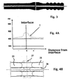
- Another way is to compensate the weaker strength in the soft zones by bumping up the rod end before friction welding (Fig. 3).
- One object of the present invention is to provide a friction welded rock drilling product wherein the heat affected zone is as strong as the product itself.
- Another object of the present invention is to provide a friction welded rock drilling product having a high strength weld.
- Still another object of the present invention is to provide an effective method for manufacturing rock drilling products by friction welding without softening the element.
- Still another object of the present invention is to provide an effective method for manufacturing rock drilling products such as rock drill rods and shank adapters combined from two or more pieces which are friction welded together without subsequent carburation or other heat treating process.
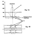
- Fig. 1 A shows a core hardness distribution graph in the longitudinal direction of a prior art friction weld of two drill steel ends shown in Fig. 1B before heat treatment.
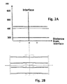
- Fig. 2A shows a core hardness distribution graph of the prior art friction weld of two drill steel ends shown in Fig. 2B after heat treatment.
- Fig. 3 shows a prior art bumped up rod before friction welding in a longitudinal cross-section.
- Fig. 4A shows a core hardness distribution graph in the longitudinal direction of a friction weld of two drill steel ends according to the present invention shown in Fig. 4B without heat treatment.
- Fig. 5 shows a core hardness distribution graph of a friction weld of two drill steel ends according to the present invention in comparison with the conventional friction weld.
- Fig. 6 shows a schematic Fe-C phase diagram of a material used in the element according to the present invention.
- the drill tool preferably a drill or a rod for percussive drilling to be manufactured usually includes a stationary or non-rotatable component 25 and a rotatable component 22.
- the components 22,25 are made of steel and before friction welding starts, the core material of each component is uniform and is as such called parent material.
- a chuck means is opened and the shank 22 of the drill bit is inserted therein.
- the chuck means is closed to grip the shank in an aligned position.
- clamp means is opened and the end of the drill rod 25 is inserted therein.
- the clamp means is closed to grip the rod in an aligned position.
- the drill bit starts to rotate and the clamp means feeds the free end of the rod towards and into contact with the free end of the bit.
- the heat produced during friction welding make abutting ends possible to forge.
- the relative rotation of the components is stopped and the components are pushed further together and cooled, as in Fig. 4B.
- the method of friction welding is more specifically described in SE-A-9502153-1.
- the friction weld will comprise soft zones Z about the interface as shown in Figs. 1A and 1B.
- the interface can be defined as the bonding zone between two components.
- HAZ heat affected zone
- the core hardness profile is shown with a dotted line I and the hardness substantially increases from the parent material towards the interface.
- a suitable steel shall have higher hot hardness and preferably a secondary hardening between 550-610°C.
- higher hot hardness is here meant that the steel used in connection with the present invention has a hot hardness about 200 HV0.5 (HV0.5 is Vickers hardness with a load of 0.5 kp) at 600 °C compared to a conventional steel wherein the hot hardness is about 100 HV0.5 at 600 °C.
- the core hardness of the softest part of the HAZ in the drill rod according to the present invention is higher or about equal to the hardness of the parent material but not less than 3% lower than the hardness of the parent material.
- the minimum hardness in the "soft zone" after friction welding shall be higher than or about 400 HV1 and not less than 390 HV1.
- the minimum hardness in the soft zone Z after friction welding is much lower than 400 HV1 and normally about 325 HV1.
- the component and the rod shall have a hardness in the HAZ that is higher than or about 400 HV1 and not less than 390 HV1.
- the strength in the HAZ is comparable with that of the parent, not heat affected steel, material.
- the hardness, shown by a line I in Fig. 5, in the normally soft zone is at least at the same level as the normal core hardness, shown with a dotted line P in Fig. 5, in a conventional normalized drill rod, i.e. it shall be higher than 400 HV1.
- the steel in the presently claimed product shall have high hot hardness.
- the end piece might be normalized or carburized or may have been subjected to any other high temperature heat treatment. High temperature heat treatment here means that the steel has been heated above A1 temperature i.e.
- the heat treatment may be case hardening (carburizing), carbonitriding, boriding, hf surface induction hardening etc. It might also be some sort of surfacing like laser surface welding, powder spraying (fused coating) etc.
- the main elements, normally Cr, Mo and V are held at a level that gives a HAZ hardness of at least 390 HV1.
- the chemical composition range for the steel type used in a rod according to the present invention is in weight-% 0.15-0.40 C; max 1.5 Si; min 0.2 Mn; 0.5-1.5 Cr; 0.5-4 Ni; 0.5-2 Mo; max 0.5 V; max 0.5 W; max 0.5 Ti; max 0.1 Nb and 0.05 Al; the balance being Fe.
- Example of such steel is 0.18C; 0.9Si; 1,2Cr; 1.8Ni; 0.75Mo and 0.1V.
- B is another element that can be used as grain refiner together with nitrogen.
- the method for producing a friction welded product for rock drilling comprises the steps of providing components 22 and 25 of parent material, each having a high hot hardness, providing clamp means for clamping the first component 25, providing rotation means for rotating the second component 22, putting free ends of the first and second components together and rotating the first and second components relative to each other so as to form a weld 27 and cooling the weld to room temperature thereby keeping the lowest core hardness of the heat affected zone above 390 HV1.
- any of the components 22 or 25 may be stationary while the other component 25 or 22 is rotatable during friction welding.
- the free ends of the rotatable 22 and non-rotatable 25 components can be joint prepared or free from joint preparation and have end surfaces substantially perpendicular to a rotational axis of the components.
- the method according to the present invention provides a welding process wherein no heat treatment is necessary after friction welding. It is possible to apply corrosion protection substantially directly after friction welding and cooling. It is furthermore not necessary to bump up the end of the product since there will be no soft zones in the vicinity of the interface. Costly finishing operations are thus avoided since the friction welded product instantly will obtain a high strength weld.
Landscapes
- Engineering & Computer Science (AREA)
- Mechanical Engineering (AREA)
- Chemical & Material Sciences (AREA)
- Geology (AREA)
- Materials Engineering (AREA)
- Organic Chemistry (AREA)
- Metallurgy (AREA)
- Life Sciences & Earth Sciences (AREA)
- Mining & Mineral Resources (AREA)
- General Life Sciences & Earth Sciences (AREA)
- Fluid Mechanics (AREA)
- Environmental & Geological Engineering (AREA)
- Physics & Mathematics (AREA)
- Geochemistry & Mineralogy (AREA)
- Pressure Welding/Diffusion-Bonding (AREA)
- Earth Drilling (AREA)
- Perforating, Stamping-Out Or Severing By Means Other Than Cutting (AREA)
- Processing Of Stones Or Stones Resemblance Materials (AREA)
- Drilling And Boring (AREA)
- Manufacture Of Macromolecular Shaped Articles (AREA)
- Polishing Bodies And Polishing Tools (AREA)
Claims (5)
- Reibgeschweißtes Produkt für Gesteinsbohren, mit einer ersten Komponente (25) und einer zweiten Komponente (22) von Ursprungsmaterial, welche durch eine Reibschweißung (27) aneinandergefügt werden, wobei die Schweißfläche aus einem Material aus einer Komponente oder aus Komponenten besteht, die einen zentralen inneren Durchgang (26) haben, wobei die Reibschweißung eine Grenzfläche hat,
dadurch gekennzeichnet, daß die Komponenten aus einem Stahl hergestellt sind, der eine chemische Zusammensetzung derart hat, daß die Härte in dem am meisten angelassenen bzw. getemperten Teil der von Wärme beeinflußten Zone dicht an der Grenzfläche mindestens dieselbe ist wie für die Kernhärte der Komponente mit normaler Härte, wenn nach dem Reibschweißen eine Kühlung auf Raumtemperatur erfolgte, wodurch man eine minimale Kernhärte an der durch Wärme beeinflußten Zone hat, die höher ist als 400 HV1 oder etwa 400 HV1 ist und nicht weniger als 390 HV1 ist, und wobei der benutzte Stahl eine Heißhärte von etwa 200 HV0,5 bei 600°C und vorzugsweise eine sekundäre Härtung zwischen 550 - 610°C hat. - Reibgeschweißtes Produkt nach Anspruch 1, wobei der in den Komponenten verwendete Stahltyp eine chemische Zusammensetzung hat, die in dem Intervall in Gewichtsprozent liegt: 0,15 - 0,40 C; maximal 1,5 Si; minimal 0,2 Mn; 0,5 - 1,5 Cr; 0,5 - 4 Ni; 0,5 - 2 Mo; maximal 0,5 V; maximal 0,5 W; maximal 0,5 Ti; maximal 0,1 Nb und 0,05 Al; wobei der Rest Eisen ist, vorzugsweise 0,18 C; 0,9 Si; 1,2 Cr; 1,8 Ni; 0,75 Mo und 0,1 V, wobei der Rest Eisen ist.
- Reibgeschweißtes Produkt nach Anspruch 1 oder 2, wobei das Produkt ein Gesteinsbohrstab oder ein Schaftadapter ist.
- Verfahren zur Herstellung eines reibgeschweißten Produktes für das Gesteinsbohren, mit einer ersten Komponente (25) und einer zweiten Komponente (22) von ursprünglichem Material, welche durch eine Reibschweißung (27) aneinandergefügt werden, wobei die Komponenten einen zentralen inneren Durchgang (26) haben, wobei jede Komponente ein freies Ende hat, das geeignet derart ausgestaltet ist, daß es mit einem anderen freien Ende verschweißt wird, wodurch eine Reibschweißung (27) erzeugt wird, und das Verfahren die Schritte aufweist:dadurch gekennzeichnet, daß das Verfahren die zusätzlichen Schritte aufweist:Vorsehen von Klemmitteln zum Einklemmen der ersten Komponente (25),Vorsehen von Drehmitteln zum Drehen der zweiten Komponente (22),Zusammenbringen der freien Enden der ersten und zweiten Komponenten und Drehen der ersten und zweiten Komponenten relativ zueinander zur Bildung einer Schweißung,Vorsehen von Komponenten (22, 25) von Ursprungsmaterial, deren jede eine hohe Heißhärte von etwa 200 HV0,5 bei 600°C und vorzugsweise ein sekundäres Härten zwischen 550 - 610°C hat undKühlen der Schweißung auf Raumtemperatur, wodurch die niedrigste Kemhärte der durch Wärme beeinflußten Zone über 390 HV1 gehalten wird.
- Verfahren nach Anspruch 4, wobei freie Enden der drehbaren (22) und nicht drehbaren (25) Komponenten verbunden werden, wobei die freien Enden zum Aneinanderfügen vorbereitet oder frei von der Vorbereitung zum Aneinanderfügen sind und Endoberflächen haben, die im wesentlichen senkrecht zu einer Drehachse der Komponenten liegen.
Applications Claiming Priority (3)
| Application Number | Priority Date | Filing Date | Title |
|---|---|---|---|
| SE9600217A SE506178C2 (sv) | 1996-01-22 | 1996-01-22 | Friktionssvetsad produkt för bergborrning samt förfarande för tillverkning av produkten |
| SE9600217 | 1996-01-22 | ||
| PCT/SE1997/000086 WO1997027022A1 (en) | 1996-01-22 | 1997-01-20 | Friction welded product for rock drilling and method for manufacturing the product |
Publications (2)
| Publication Number | Publication Date |
|---|---|
| EP0886554A1 EP0886554A1 (de) | 1998-12-30 |
| EP0886554B1 true EP0886554B1 (de) | 2002-04-10 |
Family
ID=20401099
Family Applications (1)
| Application Number | Title | Priority Date | Filing Date |
|---|---|---|---|
| EP97901871A Expired - Lifetime EP0886554B1 (de) | 1996-01-22 | 1997-01-20 | Reibungsgeschweisstes gesteinbohrwerkzeug und verfahren zu seiner herstellung |
Country Status (11)
| Country | Link |
|---|---|
| US (1) | US5919578A (de) |
| EP (1) | EP0886554B1 (de) |
| JP (1) | JP2000503903A (de) |
| AT (1) | ATE215862T1 (de) |
| AU (1) | AU708065B2 (de) |
| BR (1) | BR9707047A (de) |
| CA (1) | CA2243273C (de) |
| DE (1) | DE69711858T2 (de) |
| SE (1) | SE506178C2 (de) |
| WO (1) | WO1997027022A1 (de) |
| ZA (1) | ZA97447B (de) |
Families Citing this family (20)
| Publication number | Priority date | Publication date | Assignee | Title |
|---|---|---|---|---|
| US6448044B2 (en) | 1996-04-03 | 2002-09-10 | Human Genome Sciences, Inc. | DNA encoding human natural killer cell activating factor II |
| SE509941C2 (sv) * | 1997-09-10 | 1999-03-29 | Sandvik Ab | Metod för att maskera borrelement vid termokemisk ytbehandling samt borrelement för slående borrning |
| WO2000005774A1 (en) * | 1998-07-23 | 2000-02-03 | Massachusetts Institute Of Technology | Block copolymer electrolyte |
| BR0016258A (pt) * | 1999-12-07 | 2002-08-20 | Carburação de aços de alta velocidade, com baixo teor de carbono, baixo teor de cromo | |
| AU4522501A (en) * | 1999-12-10 | 2001-06-18 | Ingersoll-Rand Company | Drill rod having selectively hardened sections |
| DE10034712A1 (de) * | 2000-07-17 | 2002-02-07 | Arimedes Biotechnology Gmbh | Verbrückte Glykokonjugate |
| DE10120399A1 (de) * | 2001-04-25 | 2002-10-31 | Daimler Chrysler Ag | Drehstabfeder |
| SE524322C2 (sv) * | 2002-09-24 | 2004-07-27 | Sandvik Ab | Borrstång och metod för att tillverka denna |
| JP5040206B2 (ja) * | 2006-07-26 | 2012-10-03 | Jfeスチール株式会社 | 摩擦撹拌接合用の低合金構造用鋼 |
| JP5194522B2 (ja) * | 2007-03-30 | 2013-05-08 | Jfeスチール株式会社 | 摩擦撹拌接合法の施工性に優れた高強度高加工性熱延鋼板およびその製造方法 |
| CN201301670Y (zh) * | 2008-04-23 | 2009-09-02 | 长年Tm公司 | 双钢冲击钻杆 |
| DE102009059270A1 (de) * | 2009-12-22 | 2011-06-30 | EJOT GmbH & Co. KG, 57334 | Reibschweißverbindung von mindestens zwei aufeinander liegenden plattenförmigen Bauteilen |
| JP5523373B2 (ja) | 2011-02-18 | 2014-06-18 | 三菱マテリアル株式会社 | 掘削用中空鋼ロッドとその製造方法 |
| CN102071363A (zh) * | 2011-02-25 | 2011-05-25 | 上海海隆石油管材研究所 | 一种适用于高寒地区的钻杆管体用钢 |
| US9816328B2 (en) * | 2012-10-16 | 2017-11-14 | Smith International, Inc. | Friction welded heavy weight drill pipes |
| EP2746419A1 (de) | 2012-12-20 | 2014-06-25 | Sandvik Intellectual Property AB | Bainitstahl für Gesteinsbohrkomponenten |
| US20190337088A1 (en) * | 2018-05-04 | 2019-11-07 | GM Global Technology Operations LLC | Welding method and part made by the welding method |
| WO2021208181A1 (zh) * | 2020-04-14 | 2021-10-21 | 北京科技大学 | 一种低温高韧高温高强及高淬透性热模钢及制备技术 |
| CN112322981B (zh) * | 2020-11-06 | 2022-03-15 | 首钢贵阳特殊钢有限责任公司 | 一种凿岩用h22及h25钎杆中空钢 |
| JPWO2023162502A1 (de) * | 2022-02-25 | 2023-08-31 |
Family Cites Families (10)
| Publication number | Priority date | Publication date | Assignee | Title |
|---|---|---|---|---|
| US3134169A (en) * | 1963-04-24 | 1964-05-26 | American Mach & Foundry | Friction welding |
| US4181845A (en) * | 1977-07-11 | 1980-01-01 | Smith International, Inc. | Apparatus for tempering the weld between a tool joint connector and a drill pipe tube |
| DE3123963C2 (de) * | 1981-06-19 | 1985-05-15 | Berchem & Schaberg Gmbh, 4650 Gelsenkirchen | Gesteinsschneidkopf für einen Schneidkopf-Saugbagger |
| DE3136077C1 (de) * | 1981-09-11 | 1982-10-28 | Berchem & Schaberg Gmbh, 4650 Gelsenkirchen | Gesteinsschneidkopf fuer Saugbagger od.dgl. |
| US4597456A (en) * | 1984-07-23 | 1986-07-01 | Cdp, Ltd. | Conical cutters for drill bits, and processes to produce same |
| US4582242A (en) * | 1984-08-17 | 1986-04-15 | Spindler Dietmar E | Method of making formed end metal products |
| SE8501698L (sv) * | 1985-04-04 | 1986-10-05 | Santrade Ltd | Borrkrona |
| US5088638A (en) * | 1985-11-26 | 1992-02-18 | Karaev Islam K O | Method for making sucker rods |
| JPH0742837B2 (ja) * | 1986-06-13 | 1995-05-10 | 塚本精機株式会社 | ドリルビツトのカツタ−用回転軸封装置 |
| US4817852A (en) * | 1987-10-08 | 1989-04-04 | T. H. Industries | Method of replacing drill bit heads |
-
1996
- 1996-01-22 SE SE9600217A patent/SE506178C2/sv not_active IP Right Cessation
-
1997
- 1997-01-20 EP EP97901871A patent/EP0886554B1/de not_active Expired - Lifetime
- 1997-01-20 BR BR9707047A patent/BR9707047A/pt not_active Application Discontinuation
- 1997-01-20 WO PCT/SE1997/000086 patent/WO1997027022A1/en not_active Ceased
- 1997-01-20 CA CA002243273A patent/CA2243273C/en not_active Expired - Fee Related
- 1997-01-20 ZA ZA9700447A patent/ZA97447B/xx unknown
- 1997-01-20 AU AU15621/97A patent/AU708065B2/en not_active Ceased
- 1997-01-20 JP JP9526775A patent/JP2000503903A/ja active Pending
- 1997-01-20 AT AT97901871T patent/ATE215862T1/de not_active IP Right Cessation
- 1997-01-20 DE DE69711858T patent/DE69711858T2/de not_active Expired - Fee Related
- 1997-01-22 US US08/787,220 patent/US5919578A/en not_active Expired - Fee Related
Also Published As
| Publication number | Publication date |
|---|---|
| AU1562197A (en) | 1997-08-20 |
| SE9600217L (sv) | 1997-07-23 |
| ATE215862T1 (de) | 2002-04-15 |
| BR9707047A (pt) | 1999-07-20 |
| AU708065B2 (en) | 1999-07-29 |
| ZA97447B (en) | 1997-07-29 |
| CA2243273C (en) | 2005-09-13 |
| SE506178C2 (sv) | 1997-11-17 |
| CA2243273A1 (en) | 1997-07-31 |
| JP2000503903A (ja) | 2000-04-04 |
| WO1997027022A1 (en) | 1997-07-31 |
| SE9600217D0 (sv) | 1996-01-22 |
| US5919578A (en) | 1999-07-06 |
| DE69711858T2 (de) | 2003-01-16 |
| DE69711858D1 (de) | 2002-05-16 |
| EP0886554A1 (de) | 1998-12-30 |
Similar Documents
| Publication | Publication Date | Title |
|---|---|---|
| EP0886554B1 (de) | Reibungsgeschweisstes gesteinbohrwerkzeug und verfahren zu seiner herstellung | |
| AU725803B2 (en) | Friction welded drill rod and method for manufacturing the rod | |
| US4303137A (en) | Method for making a cone for a rock bit and product | |
| EP3330034B1 (de) | Reibschweissverfahren und geschweisste struktur | |
| CA3030731C (en) | Wear resistant drill pipe for use in the downhole environment | |
| US7540402B2 (en) | Method for controlling weld metal microstructure using localized controlled cooling of seam-welded joints | |
| KR100952558B1 (ko) | 열 영향 영역의 제거 및 감소에 의한 합금 강 용접조인트의 수명 연장 방법 | |
| AU716765B2 (en) | Friction welded drill rod and method for manufacturing the rod | |
| US5988301A (en) | Drill rod and method for its manufacture | |
| JP2023504047A (ja) | 膨張クランプ装置およびその製造方法 | |
| WO2001042615A2 (en) | Drill rod | |
| Amborn et al. | Modern side-shafts for passenger cars: manufacturing processes I | |
| US5272315A (en) | Welding process for hardenable or hardened steel | |
| EP1097778A2 (de) | Verfahren zur Herstellung von Werkstücken aus metallischen Materialen und mittels eines solchen Verfahren hergestellte Werkstücke | |
| JPH01241306A (ja) | 複合リングロール | |
| Stotler | Procedure Development and Practice Considerations for Inertia and Direct-Drive Friction Welding | |
| HU187116B (en) | Tool holder for cutting machines and method for producing same | |
| HK1114815B (en) | Methods for extending the life of alloy steel welded joints by elimination and reduction of the haz |
Legal Events
| Date | Code | Title | Description |
|---|---|---|---|
| PUAI | Public reference made under article 153(3) epc to a published international application that has entered the european phase |
Free format text: ORIGINAL CODE: 0009012 |
|
| 17P | Request for examination filed |
Effective date: 19980620 |
|
| AK | Designated contracting states |
Kind code of ref document: A1 Designated state(s): AT DE FI FR GB IE SE |
|
| GRAG | Despatch of communication of intention to grant |
Free format text: ORIGINAL CODE: EPIDOS AGRA |
|
| GRAG | Despatch of communication of intention to grant |
Free format text: ORIGINAL CODE: EPIDOS AGRA |
|
| GRAH | Despatch of communication of intention to grant a patent |
Free format text: ORIGINAL CODE: EPIDOS IGRA |
|
| 17Q | First examination report despatched |
Effective date: 20010817 |
|
| GRAH | Despatch of communication of intention to grant a patent |
Free format text: ORIGINAL CODE: EPIDOS IGRA |
|
| REG | Reference to a national code |
Ref country code: GB Ref legal event code: IF02 |
|
| GRAA | (expected) grant |
Free format text: ORIGINAL CODE: 0009210 |
|
| AK | Designated contracting states |
Kind code of ref document: B1 Designated state(s): AT DE FI FR GB IE SE |
|
| REF | Corresponds to: |
Ref document number: 215862 Country of ref document: AT Date of ref document: 20020415 Kind code of ref document: T |
|
| REG | Reference to a national code |
Ref country code: IE Ref legal event code: FG4D |
|
| REF | Corresponds to: |
Ref document number: 69711858 Country of ref document: DE Date of ref document: 20020516 |
|
| PG25 | Lapsed in a contracting state [announced via postgrant information from national office to epo] |
Ref country code: SE Free format text: LAPSE BECAUSE OF FAILURE TO SUBMIT A TRANSLATION OF THE DESCRIPTION OR TO PAY THE FEE WITHIN THE PRESCRIBED TIME-LIMIT Effective date: 20020710 |
|
| ET | Fr: translation filed | ||
| PGFP | Annual fee paid to national office [announced via postgrant information from national office to epo] |
Ref country code: FR Payment date: 20030110 Year of fee payment: 7 |
|
| PGFP | Annual fee paid to national office [announced via postgrant information from national office to epo] |
Ref country code: FI Payment date: 20030114 Year of fee payment: 7 |
|
| PGFP | Annual fee paid to national office [announced via postgrant information from national office to epo] |
Ref country code: GB Payment date: 20030115 Year of fee payment: 7 |
|
| PGFP | Annual fee paid to national office [announced via postgrant information from national office to epo] |
Ref country code: DE Payment date: 20030130 Year of fee payment: 7 |
|
| PLBE | No opposition filed within time limit |
Free format text: ORIGINAL CODE: 0009261 |
|
| STAA | Information on the status of an ep patent application or granted ep patent |
Free format text: STATUS: NO OPPOSITION FILED WITHIN TIME LIMIT |
|
| 26N | No opposition filed |
Effective date: 20030113 |
|
| PG25 | Lapsed in a contracting state [announced via postgrant information from national office to epo] |
Ref country code: GB Free format text: LAPSE BECAUSE OF NON-PAYMENT OF DUE FEES Effective date: 20040120 Ref country code: FI Free format text: LAPSE BECAUSE OF NON-PAYMENT OF DUE FEES Effective date: 20040120 |
|
| PG25 | Lapsed in a contracting state [announced via postgrant information from national office to epo] |
Ref country code: DE Free format text: LAPSE BECAUSE OF NON-PAYMENT OF DUE FEES Effective date: 20040803 |
|
| GBPC | Gb: european patent ceased through non-payment of renewal fee |
Effective date: 20040120 |
|
| PG25 | Lapsed in a contracting state [announced via postgrant information from national office to epo] |
Ref country code: FR Free format text: LAPSE BECAUSE OF NON-PAYMENT OF DUE FEES Effective date: 20040930 |
|
| REG | Reference to a national code |
Ref country code: FR Ref legal event code: ST |
|
| PGFP | Annual fee paid to national office [announced via postgrant information from national office to epo] |
Ref country code: IE Payment date: 20100118 Year of fee payment: 14 |
|
| PGFP | Annual fee paid to national office [announced via postgrant information from national office to epo] |
Ref country code: AT Payment date: 20100113 Year of fee payment: 14 |
|
| REG | Reference to a national code |
Ref country code: IE Ref legal event code: MM4A |
|
| PG25 | Lapsed in a contracting state [announced via postgrant information from national office to epo] |
Ref country code: AT Free format text: LAPSE BECAUSE OF NON-PAYMENT OF DUE FEES Effective date: 20110120 |
|
| PG25 | Lapsed in a contracting state [announced via postgrant information from national office to epo] |
Ref country code: IE Free format text: LAPSE BECAUSE OF NON-PAYMENT OF DUE FEES Effective date: 20110120 |