EP0886355A3 - Locking arrangement for the operating panel of a low voltage, power switch - Google Patents
Locking arrangement for the operating panel of a low voltage, power switch Download PDFInfo
- Publication number
- EP0886355A3 EP0886355A3 EP98250217A EP98250217A EP0886355A3 EP 0886355 A3 EP0886355 A3 EP 0886355A3 EP 98250217 A EP98250217 A EP 98250217A EP 98250217 A EP98250217 A EP 98250217A EP 0886355 A3 EP0886355 A3 EP 0886355A3
- Authority
- EP
- European Patent Office
- Prior art keywords
- control panel
- circuit breaker
- display
- power switch
- low voltage
- Prior art date
- Legal status (The legal status is an assumption and is not a legal conclusion. Google has not performed a legal analysis and makes no representation as to the accuracy of the status listed.)
- Granted
Links
Classifications
-
- H—ELECTRICITY
- H02—GENERATION; CONVERSION OR DISTRIBUTION OF ELECTRIC POWER
- H02B—BOARDS, SUBSTATIONS OR SWITCHING ARRANGEMENTS FOR THE SUPPLY OR DISTRIBUTION OF ELECTRIC POWER
- H02B11/00—Switchgear having carriage withdrawable for isolation
- H02B11/02—Details
- H02B11/10—Indicating electrical condition of gear; Arrangement of test sockets
-
- H—ELECTRICITY
- H02—GENERATION; CONVERSION OR DISTRIBUTION OF ELECTRIC POWER
- H02B—BOARDS, SUBSTATIONS OR SWITCHING ARRANGEMENTS FOR THE SUPPLY OR DISTRIBUTION OF ELECTRIC POWER
- H02B11/00—Switchgear having carriage withdrawable for isolation
- H02B11/12—Switchgear having carriage withdrawable for isolation with isolation by horizontal withdrawal
- H02B11/127—Withdrawal mechanism
- H02B11/133—Withdrawal mechanism with interlock
Landscapes
- Engineering & Computer Science (AREA)
- Power Engineering (AREA)
- Switch Cases, Indication, And Locking (AREA)
- Breakers (AREA)
- Driving Mechanisms And Operating Circuits Of Arc-Extinguishing High-Tension Switches (AREA)
Abstract
Die Erfindung betrifft eine Verriegelung für Bedienpulte von
Niederspannungs-Leistungsschaltern, durch die eine Demontage
des Bedienpultes bei in Betrieb befindlichem, insbesondere
bei eingeschaltetem Leistungsschalter verhindert wird.
Hierdurch soll die Sicherheit des Benutzers verbessert
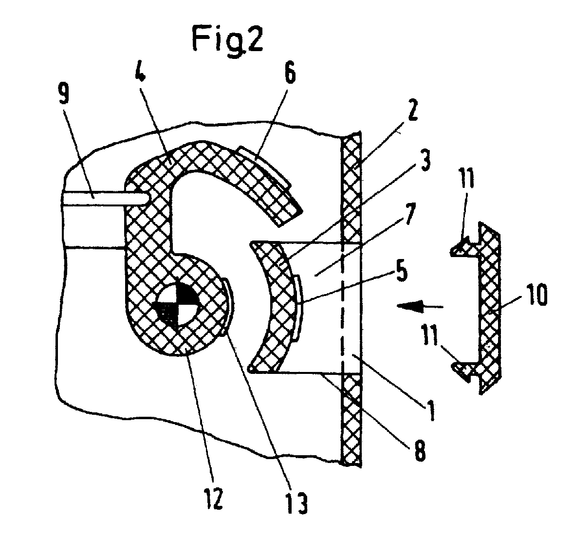
werden. Das wird dadurch erreicht, daß hinter der Anzeigeöffnung
(1) im Bedienpult (2) ein Sperrsteg (3) angeordnet
ist, und daß der Anzeigehebel (4) in der Stellung "EIN" des
Leistungsschalters hakenartig hinter diesen Sperrsteg (3)
greift. Zweckmäßig ist der Sperrsteg (3) zusammen mit der
Anzeigeöffnung (1) einstückig mit dem Bedienpult (2)
hergestellt. Die Öse (7), die durch den Sperrsteg (3) und
dessen Seitenteile (8) am Bedienpult (2) gebildet wird, ist
mechanisch relativ zum Anzeigehebel (4) schwächer
ausgebildet. Hierdurch wird eine Sollbruchstelle an der Öse
(7) geschaffen, damit bei einer Fehlbedienung nicht der
Anzeigehebel (4) beschädigt wird, der verhältnismäßig schwer
austauschbar ist.
Applications Claiming Priority (2)
| Application Number | Priority Date | Filing Date | Title |
|---|---|---|---|
| DE19727695 | 1997-06-20 | ||
| DE19727695A DE19727695A1 (en) | 1997-06-20 | 1997-06-20 | Interlock for the control panel of a low-voltage circuit breaker |
Publications (3)
| Publication Number | Publication Date |
|---|---|
| EP0886355A2 EP0886355A2 (en) | 1998-12-23 |
| EP0886355A3 true EP0886355A3 (en) | 1999-03-10 |
| EP0886355B1 EP0886355B1 (en) | 2001-10-31 |
Family
ID=7834048
Family Applications (1)
| Application Number | Title | Priority Date | Filing Date |
|---|---|---|---|
| EP98250217A Expired - Lifetime EP0886355B1 (en) | 1997-06-20 | 1998-06-17 | Locking arrangement for the operating panel of a low voltage, power switch |
Country Status (2)
| Country | Link |
|---|---|
| EP (1) | EP0886355B1 (en) |
| DE (2) | DE19727695A1 (en) |
Cited By (1)
| Publication number | Priority date | Publication date | Assignee | Title |
|---|---|---|---|---|
| US7141747B2 (en) | 2004-12-06 | 2006-11-28 | Siemens Aktiengesellschaft | Switching apparatus having a withdrawable-part rack and a lockable power circuit breaker |
Families Citing this family (3)
| Publication number | Priority date | Publication date | Assignee | Title |
|---|---|---|---|---|
| DE10251002B3 (en) | 2002-10-30 | 2004-05-27 | Siemens Ag | breakers |
| DE102006015303A1 (en) * | 2006-03-28 | 2007-10-11 | Siemens Ag | Cover for a fuse-switch-disconnector and fuse-switch-disconnector |
| CN113224682B (en) * | 2021-05-31 | 2024-07-23 | 上海电气集团股份有限公司 | Chassis truck locking mechanism |
Citations (5)
| Publication number | Priority date | Publication date | Assignee | Title |
|---|---|---|---|---|
| US2512505A (en) * | 1948-09-08 | 1950-06-20 | Trumbull Electric Mfg Co | Operating means for enclosed switches |
| DE1082327B (en) * | 1957-06-13 | 1960-05-25 | Licentia Gmbh | Locking device for mobile switches in control cabinets |
| US3288956A (en) * | 1965-03-01 | 1966-11-29 | Gen Electric | Draw-out switch-gear interlock apparatus |
| EP0685913A2 (en) * | 1994-06-03 | 1995-12-06 | Siemens Aktiengesellschaft | Switchgear with a switch position dependent mechanism for introduction and extraction relative to a slide-in frame |
| US5609244A (en) * | 1995-11-13 | 1997-03-11 | Reitech Corporation | Interlock device |
-
1997
- 1997-06-20 DE DE19727695A patent/DE19727695A1/en not_active Withdrawn
-
1998
- 1998-06-17 DE DE59801922T patent/DE59801922D1/en not_active Expired - Fee Related
- 1998-06-17 EP EP98250217A patent/EP0886355B1/en not_active Expired - Lifetime
Patent Citations (5)
| Publication number | Priority date | Publication date | Assignee | Title |
|---|---|---|---|---|
| US2512505A (en) * | 1948-09-08 | 1950-06-20 | Trumbull Electric Mfg Co | Operating means for enclosed switches |
| DE1082327B (en) * | 1957-06-13 | 1960-05-25 | Licentia Gmbh | Locking device for mobile switches in control cabinets |
| US3288956A (en) * | 1965-03-01 | 1966-11-29 | Gen Electric | Draw-out switch-gear interlock apparatus |
| EP0685913A2 (en) * | 1994-06-03 | 1995-12-06 | Siemens Aktiengesellschaft | Switchgear with a switch position dependent mechanism for introduction and extraction relative to a slide-in frame |
| US5609244A (en) * | 1995-11-13 | 1997-03-11 | Reitech Corporation | Interlock device |
Cited By (1)
| Publication number | Priority date | Publication date | Assignee | Title |
|---|---|---|---|---|
| US7141747B2 (en) | 2004-12-06 | 2006-11-28 | Siemens Aktiengesellschaft | Switching apparatus having a withdrawable-part rack and a lockable power circuit breaker |
Also Published As
| Publication number | Publication date |
|---|---|
| DE59801922D1 (en) | 2001-12-06 |
| EP0886355A2 (en) | 1998-12-23 |
| DE19727695A1 (en) | 1998-12-24 |
| EP0886355B1 (en) | 2001-10-31 |
Similar Documents
| Publication | Publication Date | Title |
|---|---|---|
| EP1210720B1 (en) | Manual operating device equipped with a turning handle and provided for electrical switchgears | |
| DE69405022T2 (en) | Remote-operated circuit breaker with disconnect function | |
| DE10147321B4 (en) | Switch button mechanism for a circuit breaker | |
| DE2410871C2 (en) | Electric switch with locking device | |
| DE69905765T2 (en) | SEMI-BRANCHING ELECTRICAL CONTACT | |
| DE102011087551B3 (en) | Locking mechanism for a power button of a circuit breaker | |
| EP1004158B1 (en) | Insertable and retractable switching device comprising a blocking bar which prevents wrong operation | |
| DE69108893T2 (en) | CIRCUIT ARRANGEMENT WITH A MONOSTABLY WORKING AUXILIARY SWITCH COUPLED TO A MAIN SWITCH. | |
| EP0886355A3 (en) | Locking arrangement for the operating panel of a low voltage, power switch | |
| EP0360368A3 (en) | Lever and abutting-contact arrangement for low-tension power switches with principal contacts and arcing contacts | |
| EP1134762B1 (en) | Switch | |
| DE2453194A1 (en) | Disconnecting switch safety earthing switch - has spring force drive actuated by common drive shaft in sequential manner | |
| DE602004007722T2 (en) | Automatic reclosing device for the false triggering of a switch | |
| DE69836247T2 (en) | Drive device of an electrical protective device such as a circuit breaker with a trip indicator and equipped with such a device circuit breaker | |
| DE9201409U1 (en) | Locking device against actuation, in particular re-activation of installation devices | |
| DE114542T1 (en) | CONTACTOR WITH ELECTROMAGNETICALLY OPERATED ACTION AND AUTOMATIC OPENING IN THE EVENT OF OVERVOLTAGE. | |
| EP0828278A1 (en) | Remote control for low voltage circuit breaker | |
| DE19522049C2 (en) | Mechanical safety device against pivoting the switching lever of a circuit breaker | |
| DE19628885A1 (en) | Actuator for power switchgear | |
| EP1137025B1 (en) | Security system for an electrical device | |
| DE19704083B4 (en) | Device for switching on and off of electrical appliances | |
| DE102007010015A1 (en) | Residual current circuit breaker, differential circuit breaker and combination device of circuit breaker and residual current circuit breaker or residual current device | |
| DE233884C (en) | ||
| EP0686987B1 (en) | Device for reversing commutation of a drive motor | |
| DE204926C (en) |
Legal Events
| Date | Code | Title | Description |
|---|---|---|---|
| PUAI | Public reference made under article 153(3) epc to a published international application that has entered the european phase |
Free format text: ORIGINAL CODE: 0009012 |
|
| AK | Designated contracting states |
Kind code of ref document: A2 Designated state(s): DE FR GB IT |
|
| AX | Request for extension of the european patent |
Free format text: AL;LT;LV;MK;RO;SI |
|
| PUAL | Search report despatched |
Free format text: ORIGINAL CODE: 0009013 |
|
| AK | Designated contracting states |
Kind code of ref document: A3 Designated state(s): AT BE CH CY DE DK ES FI FR GB GR IE IT LI LU MC NL PT SE |
|
| AX | Request for extension of the european patent |
Free format text: AL;LT;LV;MK;RO;SI |
|
| 17P | Request for examination filed |
Effective date: 19990419 |
|
| AKX | Designation fees paid |
Free format text: DE FR GB IT |
|
| 17Q | First examination report despatched |
Effective date: 20000725 |
|
| GRAG | Despatch of communication of intention to grant |
Free format text: ORIGINAL CODE: EPIDOS AGRA |
|
| GRAG | Despatch of communication of intention to grant |
Free format text: ORIGINAL CODE: EPIDOS AGRA |
|
| GRAH | Despatch of communication of intention to grant a patent |
Free format text: ORIGINAL CODE: EPIDOS IGRA |
|
| GRAH | Despatch of communication of intention to grant a patent |
Free format text: ORIGINAL CODE: EPIDOS IGRA |
|
| GRAA | (expected) grant |
Free format text: ORIGINAL CODE: 0009210 |
|
| AK | Designated contracting states |
Kind code of ref document: B1 Designated state(s): DE FR GB IT |
|
| REF | Corresponds to: |
Ref document number: 59801922 Country of ref document: DE Date of ref document: 20011206 |
|
| REG | Reference to a national code |
Ref country code: GB Ref legal event code: IF02 |
|
| GBT | Gb: translation of ep patent filed (gb section 77(6)(a)/1977) |
Effective date: 20020130 |
|
| PLBE | No opposition filed within time limit |
Free format text: ORIGINAL CODE: 0009261 |
|
| STAA | Information on the status of an ep patent application or granted ep patent |
Free format text: STATUS: NO OPPOSITION FILED WITHIN TIME LIMIT |
|
| 26N | No opposition filed | ||
| PGFP | Annual fee paid to national office [announced via postgrant information from national office to epo] |
Ref country code: IT Payment date: 20080626 Year of fee payment: 11 |
|
| PGFP | Annual fee paid to national office [announced via postgrant information from national office to epo] |
Ref country code: DE Payment date: 20080818 Year of fee payment: 11 |
|
| PGFP | Annual fee paid to national office [announced via postgrant information from national office to epo] |
Ref country code: GB Payment date: 20080616 Year of fee payment: 11 |
|
| GBPC | Gb: european patent ceased through non-payment of renewal fee |
Effective date: 20090617 |
|
| PG25 | Lapsed in a contracting state [announced via postgrant information from national office to epo] |
Ref country code: GB Free format text: LAPSE BECAUSE OF NON-PAYMENT OF DUE FEES Effective date: 20090617 |
|
| PG25 | Lapsed in a contracting state [announced via postgrant information from national office to epo] |
Ref country code: DE Free format text: LAPSE BECAUSE OF NON-PAYMENT OF DUE FEES Effective date: 20100101 |
|
| PG25 | Lapsed in a contracting state [announced via postgrant information from national office to epo] |
Ref country code: IT Free format text: LAPSE BECAUSE OF NON-PAYMENT OF DUE FEES Effective date: 20090617 |
|
| PGFP | Annual fee paid to national office [announced via postgrant information from national office to epo] |
Ref country code: FR Payment date: 20110630 Year of fee payment: 14 |
|
| REG | Reference to a national code |
Ref country code: FR Ref legal event code: ST Effective date: 20130228 |
|
| PG25 | Lapsed in a contracting state [announced via postgrant information from national office to epo] |
Ref country code: FR Free format text: LAPSE BECAUSE OF NON-PAYMENT OF DUE FEES Effective date: 20120702 |