EP0886355A2 - Locking arrangement for the operating panel of a low voltage, power switch - Google Patents
Locking arrangement for the operating panel of a low voltage, power switch Download PDFInfo
- Publication number
- EP0886355A2 EP0886355A2 EP98250217A EP98250217A EP0886355A2 EP 0886355 A2 EP0886355 A2 EP 0886355A2 EP 98250217 A EP98250217 A EP 98250217A EP 98250217 A EP98250217 A EP 98250217A EP 0886355 A2 EP0886355 A2 EP 0886355A2
- Authority
- EP
- European Patent Office
- Prior art keywords
- control panel
- lock according
- circuit breaker
- lever
- display
- Prior art date
- Legal status (The legal status is an assumption and is not a legal conclusion. Google has not performed a legal analysis and makes no representation as to the accuracy of the status listed.)
- Granted
Links
Images

Classifications
-
- H—ELECTRICITY
- H02—GENERATION; CONVERSION OR DISTRIBUTION OF ELECTRIC POWER
- H02B—BOARDS, SUBSTATIONS OR SWITCHING ARRANGEMENTS FOR THE SUPPLY OR DISTRIBUTION OF ELECTRIC POWER
- H02B11/00—Switchgear having carriage withdrawable for isolation
- H02B11/02—Details
- H02B11/10—Indicating electrical condition of gear; Arrangement of test sockets
-
- H—ELECTRICITY
- H02—GENERATION; CONVERSION OR DISTRIBUTION OF ELECTRIC POWER
- H02B—BOARDS, SUBSTATIONS OR SWITCHING ARRANGEMENTS FOR THE SUPPLY OR DISTRIBUTION OF ELECTRIC POWER
- H02B11/00—Switchgear having carriage withdrawable for isolation
- H02B11/12—Switchgear having carriage withdrawable for isolation with isolation by horizontal withdrawal
- H02B11/127—Withdrawal mechanism
- H02B11/133—Withdrawal mechanism with interlock
Definitions
- the invention relates to a lock for control panels from Low-voltage circuit breakers through which dismantling the control panel when in operation, in particular is prevented when the circuit breaker is switched on. This is intended to improve the safety of the user will.
- Removable control panels on circuit breakers with one Device for retracting and extending relative to one Slide-in frames are known, inter alia, from US Pat. No. 5,097,382, known from EP-0 269 814 B1 and DE-PS 44 20 581 C1. All Known removable control panels have the disadvantage that regardless of whether the switch is in operation or not, can be removed. It consists of removed control panel through a risk of injury mechanical elements that can then be touched openly, when an operator or a maintenance mechanic on Switch works and the switch is triggered as well possibly a danger from hot switching gases or Arc fuses caused by those from the control panel closed opening can emerge.
- the invention is therefore based on the problem of a risk of injury to avoid and prevent a user from that the control panel is in operation Low voltage circuit breaker can be dismantled.
- a lock of the control panel is provided with the switch position indicator which is inevitably actuated by the selector shaft combined and can be operated by this.
- a barrier web is arranged, and that the indicator lever in the "ON" position is hook-like reaches behind this barrier.
- the barrier is useful together with the display opening in one piece with the control panel produced.
- the barrier can be used as a carrier of the "AUS" marking be formed, the indicator lever only the Marks "ON”.
- the eyelet on the control panel is mechanically relative to the indicator lever weaker trained. This causes a predetermined breaking point created the eyelet, so that in the event of incorrect operation in shape an unwanted or unauthorized disassembly of the control panel the indicator lever is not damaged that proportionately is difficult to replace.
- the indicator lever is as Swivel hook designed so that when trying to dismantle the take-off forces no torque on the indicator lever and thus exert on the shift shaft because the effect of this Forces through the center of the indicator lever bearing runs.
- the display opening through a transparent cover are closed, preferably by means of resilient Snap hook is clickable. But it can also be screwed in or can be used with a bayonet connection be.
- Figure 1 shows schematically the switch position indicator a low-voltage circuit breaker with the locking function according to the invention in the switched on State of the circuit breaker.
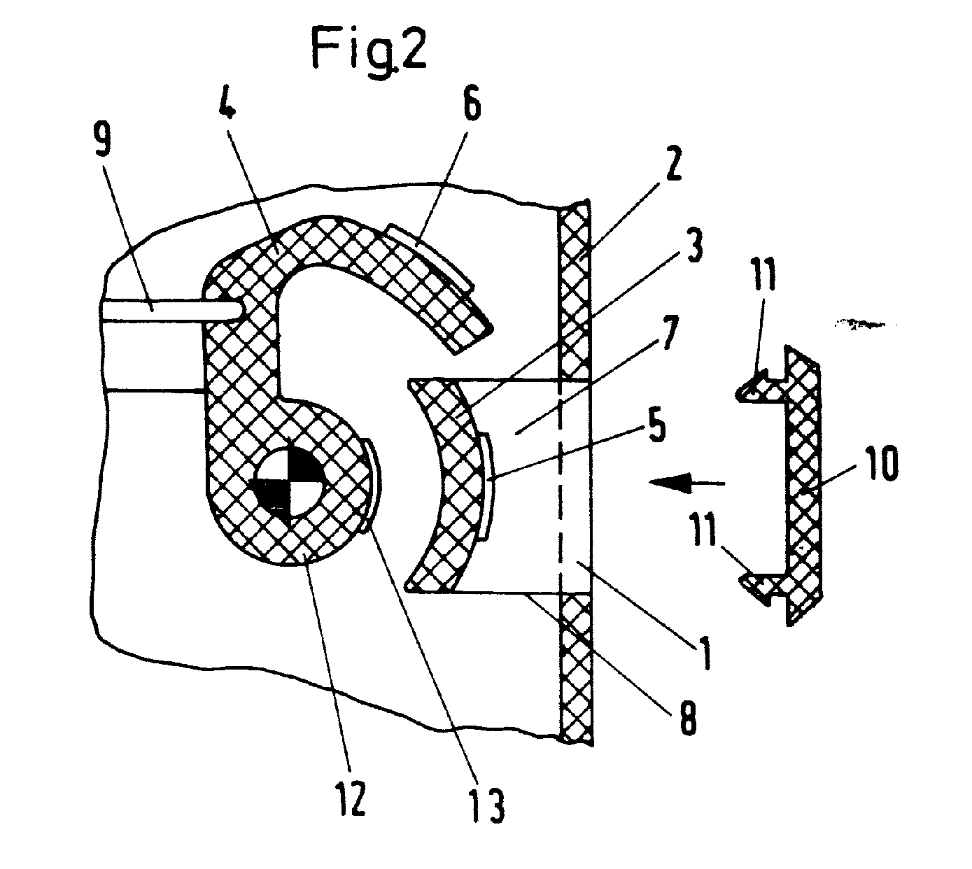
- Figure 2 shows schematically the switch position indicator a low-voltage circuit breaker with the locking function according to the invention in the switched off State of the circuit breaker.
- the switch position indicator is a Low-voltage circuit breaker with the invention Locking function when the Circuit breaker shown in which a disassembly of the Control panel is not possible. This is achieved that behind the display opening 1 in the control panel 2, a barrier 3 is arranged, and that the indicator lever 4 in the position "ON" hooks behind this barrier 3. Appropriately is the barrier web 3 together with the display opening 1 made in one piece with the control panel 2. On the Barrier 3 is marked “OFF” 5. Of the Indicator lever 4 is only marked “ON” 6.
- the eyelet 7 through the locking web 3 and its side parts 8 is formed on the control panel 2 is mechanically relative to Indicator lever 4 weaker. This will create a A predetermined breaking point on the eyelet 7 is created so that at a Incorrect operation does not damage the display lever 4 is relatively difficult to replace.
- the Display opening 1 in the control panel 2 through a transparent Cover 10 are closed by means of resilient Locking hook 11 can be snapped into the display opening 1.
- the switch position indicator is a Low-voltage circuit breaker with the invention Locking function when the Circuit breaker shown in the indicator lever 4 is not in engagement with the locking web 3, whereby disassembly of the control panel 2 is possible.
- auxiliary label "OFF" 13 On the hub 12 of the display lever 4 is an auxiliary label "OFF" 13 attached so that when the control panel is removed 2 this switch position is recognizable. This is useful Auxiliary lettering 13 sprayed on with paint to prevent a glued-on display from coming off and get lost.
- the advantages of the invention are that security of the user against an injury caused by switching movements parts of the circuit breaker that move mechanically, which are accessible when the control panel is removed or through hot arc gases that are disassembled through the opening of the Can exit control panel, is significantly improved.
Landscapes
- Engineering & Computer Science (AREA)
- Power Engineering (AREA)
- Switch Cases, Indication, And Locking (AREA)
- Breakers (AREA)
- Driving Mechanisms And Operating Circuits Of Arc-Extinguishing High-Tension Switches (AREA)
Abstract
Die Erfindung betrifft eine Verriegelung für Bedienpulte von
Niederspannungs-Leistungsschaltern, durch die eine Demontage
des Bedienpultes bei in Betrieb befindlichem, insbesondere
bei eingeschaltetem Leistungsschalter verhindert wird.
Hierdurch soll die Sicherheit des Benutzers verbessert
werden. Das wird dadurch erreicht, daß hinter der Anzeigeöffnung
(1) im Bedienpult (2) ein Sperrsteg (3) angeordnet
ist, und daß der Anzeigehebel (4) in der Stellung "EIN" des
Leistungsschalters hakenartig hinter diesen Sperrsteg (3)
greift. Zweckmäßig ist der Sperrsteg (3) zusammen mit der
Anzeigeöffnung (1) einstückig mit dem Bedienpult (2)
hergestellt. Die Öse (7), die durch den Sperrsteg (3) und
dessen Seitenteile (8) am Bedienpult (2) gebildet wird, ist
mechanisch relativ zum Anzeigehebel (4) schwächer
ausgebildet. Hierdurch wird eine Sollbruchstelle an der Öse
(7) geschaffen, damit bei einer Fehlbedienung nicht der
Anzeigehebel (4) beschädigt wird, der verhältnismäßig schwer
austauschbar ist.
Description
Die Erfindung betrifft eine Verriegelung für Bedienpulte von Niederspannungs-Leistungsschaltern, durch die eine Demontage des Bedienpultes bei in Betrieb befindlichem, insbesondere bei eingeschaltetem Leistungsschalter verhindert wird. Hierdurch soll die Sicherheit des Benutzers verbessert werden.The invention relates to a lock for control panels from Low-voltage circuit breakers through which dismantling the control panel when in operation, in particular is prevented when the circuit breaker is switched on. This is intended to improve the safety of the user will.
Abnehmbare Bedienpulte an Leistungsschaltern mit einer Einrichtung zum Einfahren und Ausfahren relativ zu einem Einschubrahmen sind unter anderem aus der US-PS 5 097 382, der EP-0 269 814 B1 und der DE-PS 44 20 581 C1 bekannt. Alle bekannten abnehmbaren Bedienpulte weisen den Nachteil auf, daß sie unabhängig davon, ob der Schalter in Betrieb ist oder nicht, abgenommen werden können. Es besteht dadurch bei abgenommenen Bedienpult eine Verletzungsgefahr durch mechanische Elemente die dann offen berührt werden können, wenn eine Bedienperson oder ein Wartungsmechaniker am Schalter arbeitet und der Schalter ausgelöst wird, sowie möglicherweise eine Gefahr durch heiße Schaltgase oder Lichtbogenausläufer, die durch die nicht vom Bedienpult verschlossene Öffnung austreten können.Removable control panels on circuit breakers with one Device for retracting and extending relative to one Slide-in frames are known, inter alia, from US Pat. No. 5,097,382, known from EP-0 269 814 B1 and DE-PS 44 20 581 C1. All Known removable control panels have the disadvantage that regardless of whether the switch is in operation or not, can be removed. It consists of removed control panel through a risk of injury mechanical elements that can then be touched openly, when an operator or a maintenance mechanic on Switch works and the switch is triggered as well possibly a danger from hot switching gases or Arc fuses caused by those from the control panel closed opening can emerge.
Der Erfindung liegt somit das Problem zugrunde, eine Verletzungsgefahr eines Benutzers zu vermeiden und zu verhindern, daß das Bedienpult eines in Betrieb befindlichen Niederspannungs-Leistungsschalters demontiert werden kann. The invention is therefore based on the problem of a risk of injury to avoid and prevent a user from that the control panel is in operation Low voltage circuit breaker can be dismantled.
Dieses Problem wird erfindungsgemäß dadurch gelöst, daß eine Verriegelung des Bedienpultes vorgesehen ist, die mit der zwangsläufig durch die Schaltwelle betätigten Schalterstellungsanzeige kombiniert und durch diese betätigbar ist. Das kann vorteilhaft dadurch geschehen, daß hinter der Anzeigeöffnung im Bedienpult ein Sperrsteg angeordnet ist, und daß der Anzeigehebel in der Stellung "EIN" hakenartig hinter diesen Sperrsteg greift. Zweckmäßig ist der Sperrsteg zusammen mit der Anzeigeöffnung einstückig mit dem Bedienpult hergestellt. In weiterer vorteilhafter Ausgestaltung der Erfindung kann der Sperrsteg als Träger der Markierung "AUS" ausgebildet sein, wobei der Anzeigehebel lediglich die Markierung "EIN" trägt.This problem is solved according to the invention in that a lock of the control panel is provided with the switch position indicator which is inevitably actuated by the selector shaft combined and can be operated by this. This can be done advantageously in that behind the Display opening in the control panel, a barrier web is arranged, and that the indicator lever in the "ON" position is hook-like reaches behind this barrier. The barrier is useful together with the display opening in one piece with the control panel produced. In a further advantageous embodiment of the Invention the barrier can be used as a carrier of the "AUS" marking be formed, the indicator lever only the Marks "ON".
Die Öse am Bedienpult ist mechanisch relativ zum Anzeigehebel schwächer ausgebildet. Hierdurch wird eine Sollbruchstelle an der Öse geschaffen, damit bei einer Fehlbedienung in Form einer ungewollten oder unerlaubten Demontage des Bedienpultes nicht der Anzeigehebel beschädigt wird, der verhältnismäßig schwer austauschbar ist.The eyelet on the control panel is mechanically relative to the indicator lever weaker trained. This causes a predetermined breaking point created the eyelet, so that in the event of incorrect operation in shape an unwanted or unauthorized disassembly of the control panel the indicator lever is not damaged that proportionately is difficult to replace.
Durch das Hintergreifen des Sperrsteges durch den mit der Schaltwelle zwangsläufig gekuppelten Anzeigehebel wird die Abnahme des Bedienpultes in der gewünschten Weise verhindert. In sinngemäß der gleichen Weise wird verhindert, daß das Bedienpult in der Schaltstellung "EIN" des Leistungsschalters an diesem montiert werden kann. Der Anzeigehebel ist als Schwenkhaken so ausgebildet, daß beim Versuch der Demontage die Abnahmekräfte kein Drehmoment auf den Anzeigehebel und damit auf die Schaltwelle ausüben, weil die Wirkung dieser Kräfte durch das Zentrum der Lagerung des Anzeigehebels verläuft. Zur Erhöhung der Schutzart des Leistungsschalters kann die Anzeigeöffnung durch eine transparente Abdeckung verschlossen werden, die vorzugsweise mittels federnder Rasthaken einrastbar ist. Sie kann aber auch einschraubbar oder mittels einer Bajonettverbindung einsetzbar ausgeführt sein.By reaching behind the barrier bar with the Gearshift shaft inevitably coupled indicator lever Removal of the control panel prevented in the desired manner. In the same way, it is prevented that the Control panel in the "ON" switch position of the circuit breaker can be mounted on this. The indicator lever is as Swivel hook designed so that when trying to dismantle the take-off forces no torque on the indicator lever and thus exert on the shift shaft because the effect of this Forces through the center of the indicator lever bearing runs. To increase the protection class of the circuit breaker can the display opening through a transparent cover are closed, preferably by means of resilient Snap hook is clickable. But it can also be screwed in or can be used with a bayonet connection be.
An der Nabe des Anzeigehebels ist eine Hilfsbeschriftung "AUS" angebracht, damit bei abgenommenem Bedienpult diese Schaltstellung erkennbar ist. Zweckmäßig ist diese Hilfsanzeige mittels Farbe aufgespritzt, um zu vermeiden, daß eine aufgeklebte Anzeige sich löst und verlorengeht.There is an auxiliary label on the hub of the display lever "OFF" attached so that when the control panel is removed Switch position is recognizable. This auxiliary display is useful sprayed on with paint to avoid that a stuck display gets loose and gets lost.
Die Erfindung wird nachfolgend anhand eines in den Figuren dargestellten bevorzugten Ausführungsbeispiels näher erläutert.The invention is described below with reference to one of the figures illustrated preferred embodiment closer explained.
Die Figur 1 zeigt schematisch die Schaltstellungsanzeige eines Niederspannungs-Leistungsschalters mit der erfindungsgemäßen Verriegelungsfunktion im eingeschalteten Zustand des Leistungsschalters.Figure 1 shows schematically the switch position indicator a low-voltage circuit breaker with the locking function according to the invention in the switched on State of the circuit breaker.
Die Figur 2 zeigt schematisch die Schaltstellungsanzeige eines Niederspannungs-Leistungsschalters mit der erfindungsgemäßen Verriegelungsfunktion im ausgeschalteten Zustand des Leistungsschalters.Figure 2 shows schematically the switch position indicator a low-voltage circuit breaker with the locking function according to the invention in the switched off State of the circuit breaker.
In der Figur 1 ist die Schaltstellungsanzeige eines
Niederspannungs-Leistungsschalters mit der erfindungsgemäßen
Verriegelungsfunktion im eingeschalteten Zustand des
Leistungsschalters dargestellt, in der eine Demontage des
Bedienpultes nicht möglich ist. Das wird dadurch erreicht,
daß hinter der Anzeigeöffnung 1 im Bedienpult 2 ein Sperrsteg
3 angeordnet ist, und daß der Anzeigehebel 4 in der Stellung
"EIN" hakenartig hinter diesen Sperrsteg 3 greift. Zweckmäßig
ist der Sperrsteg 3 zusammen mit der Anzeigeöffnung 1
einstückig mit dem Bedienpult 2 hergestellt. Auf dem
Sperrsteg 3 ist eine Markierung "AUS" 5 angebracht. Der
Anzeigehebel 4 trägt lediglich die Markierung "EIN" 6.In Figure 1, the switch position indicator is a
Low-voltage circuit breaker with the invention
Locking function when the
Circuit breaker shown in which a disassembly of the
Control panel is not possible. This is achieved
that behind the display opening 1 in the
Die Öse 7, die durch den Sperrsteg 3 und dessen Seitenteile 8
am Bedienpult 2 gebildet wird, ist mechanisch relativ zum
Anzeigehebel 4 schwächer ausgebildet. Hierdurch wird eine
Sollbruchstelle an der Öse 7 geschaffen, damit bei einer
Fehlbedienung nicht der Anzeigehebel 4 beschädigt wird, der
verhältnismäßig schwer austauschbar ist.The eyelet 7 through the
Durch das Hintergreifen des Sperrsteges 3 durch den mit der
nicht dargestellten Schaltwelle mittels eines Kraftübertragungselementes
9 zwangsläufig gekoppelten Anzeigehebel 4
wird die Abnahme des Bedienpultes 2 in der gewünschten Weise
verhindert.By reaching behind the
Der mit der nicht dargestellten Schaltwelle mittels des
Kraftübertragungselementes 9 direkt gekoppelte Anzeigehebel 4
ist als Schwenkhaken so ausgebildet, daß beim Versuch der
ungewollten bzw. unerlaubten Demontage des Bedienpultes 2 die
Abnahmekräfte kein Drehmoment auf den Anzeigehebel 4 und
damit auf die Schaltwelle ausüben, weil die Wirkung dieser
Kräfte durch das Zentrum der Lagerung des Anzeigehebels 4
verläuft. The with the shift shaft, not shown, by means of
Zur Erhöhung der Schutzart des Leistungsschalters kann die
Anzeigeöffnung 1 im Bedienpult 2 durch eine transparente
Abdeckung 10 verschlossen werden, die mittels federnder
Rasthaken 11 in die Anzeigeöffnung 1 einrastbar ist.To increase the protection class of the circuit breaker, the
Display opening 1 in the
In der Figur 2 ist die Schaltstellungsanzeige eines
Niederspannungs-Leistungsschalters mit der erfindungsgemäßen
Verriegelungsfunktion im ausgeschalteten Zustand des
Leistungsschalters dargestellt, in der sich der Anzeigehebel
4 mit dem Sperrsteg 3 nicht im Eingriff befindet, wodurch
eine Demontage des Bedienpultes 2 möglich ist.In Figure 2, the switch position indicator is a
Low-voltage circuit breaker with the invention
Locking function when the
Circuit breaker shown in the indicator lever
4 is not in engagement with the
An der Nabe 12 des Anzeigehebels 4 ist eine Hilfsbeschriftung
"AUS" 13 angebracht, damit bei abgenommenem Bedienpult 2
diese Schaltstellung erkennbar ist. Zweckmäßig ist diese
Hilfsbeschriftung 13 mittels Farbe aufgespritzt, um zu
vermeiden, daß eine aufgeklebte Anzeige sich löst und
verlorengeht.On the
Die Vorteile der Erfindung bestehen darin, daß die Sicherheit des Benutzers gegen eine Verletzung durch bei Schaltbewegungen des Leistungsschalters mechanisch bewegte Teile, die bei abgenommenem Bedienpult zugängig sind oder durch heiße Lichtbogengase, die durch die Öffnung des demontierten Bedienpultes austreten können, wesentlich verbessert wird.The advantages of the invention are that security of the user against an injury caused by switching movements parts of the circuit breaker that move mechanically, which are accessible when the control panel is removed or through hot arc gases that are disassembled through the opening of the Can exit control panel, is significantly improved.
Claims (11)
dadurch gekennzeichnet, daß sie mit der zwangsläufig durch die Schaltwelle betätigten Schaltstellungsanzeige kombiniert und durch diese betätigbar ist.Locking device for the control panel of a low-voltage circuit breaker to avoid unauthorized or unwanted dismantling of the control panel when the circuit breaker is in operation, especially when it is switched on,
characterized in that it is combined with the switch position indicator which is inevitably actuated by the selector shaft and can be actuated by it.
dadurch gekennzeichnet, daß hinter der Anzeigeöffnung (1) im Bedienpult (2) ein Sperrsteg (3) angeordnet ist, und daß der Anzeigehebel (4) in der Stellung "EIN" hakenartig hinter diesen Sperrsteg (3) greift.Lock according to claim 1,
characterized in that a locking bar (3) is arranged behind the display opening (1) in the control panel (2), and in that the display lever (4) engages like a hook behind this locking bar (3) in the "ON" position.
dadurch gekennzeichnet, daß der Sperrsteg (3) zusammen mit der Anzeigeöffnung (1) einstückig mit dem Bedienpult (2) hergestellt ist.Lock according to claim 1,
characterized in that the locking web (3) together with the display opening (1) is made in one piece with the control panel (2).
dadurch gekennzeichnet, daß auf dem Sperrsteg (3) eine Markierung "AUS" (5) angebracht ist und der Anzeigehebel (4) lediglich die Markierung "EIN" (6) trägt.Lock according to claim 1,
characterized in that an "OFF" mark (5) is attached to the locking web (3) and the indicator lever (4) only carries the "ON" mark (6).
dadurch gekennzeichnet, daß die Öse (7), die durch den Sperrsteg (3) und dessen Seitenteile (8) am Bedienpult (2) gebildet ist, mechanisch relativ zum Anzeigehebel (4) schwächer ausgebildet ist.Lock according to claim 1,
characterized in that the eyelet (7), which is formed by the locking web (3) and its side parts (8) on the control panel (2), is mechanically weaker relative to the indicator lever (4).
dadurch gekennzeichnet, daß der mit der nicht dargestellten Schaltwelle mittels des Kraftübertragungselementes (9) direkt gekoppelte Anzeigehebel (4) als Schwenkhaken derart ausgebildet ist, daß beim Versuch der Demontage des Bedienpultes (2) im verriegelten Zustand die Abnahmekräfte kein Drehmoment auf den Anzeigehebel (4) und damit auf die Schaltwelle ausüben, und die Wirkung dieser Kräfte durch das Zentrum der Lagerung des Anzeigehebels (4) verläuft.Lock according to claim 1,
characterized in that the indicator lever (4) directly coupled to the selector shaft (not shown) by means of the force transmission element (9) is designed as a swivel hook in such a way that when attempting to disassemble the control panel (2) in the locked state, the take-off forces do not apply any torque to the indicator lever (4 ) and thus exert on the selector shaft, and the effect of these forces runs through the center of the bearing of the indicator lever (4).
dadurch gekennzeichnet, daß zur Erhöhung der Schutzart des Leistungsschalters die Anzeigeöffnung (1) im Bedienpult (2) durch eine transparente Abdeckung (10) verschlossen ist.Lock according to claim 1,
characterized in that the display opening (1) in the control panel (2) is closed by a transparent cover (10) to increase the protection class of the circuit breaker.
dadurch gekennzeichnet, daß die Abdeckung (10) mittels federnder Rasthaken 11 in die Anzeigeöffnung (1) einrastbar ist.Lock according to claim 7,
characterized in that the cover (10) can be snapped into the display opening (1) by means of resilient latching hooks 11.
dadurch gekennzeichnet, daß die Abdeckung (10) in die Anzeigeöffnung (1) einschraubbar oder mittels einer Bajonettverbindung einsetzbar ist. Lock according to claim 7,
characterized in that the cover (10) can be screwed into the display opening (1) or inserted by means of a bayonet connection.
dadurch gekennzeichnet, daß zum Erkennen der Schaltstellung des Leistungsschalters bei abgenommenem Bedienpult (2) an der Nabe (12) des Anzeigehebels (4) eine Hilfsbeschriftung (13) angebracht ist.Lock according to claim 1,
characterized in that an auxiliary label (13) is attached to the hub (12) of the display lever (4) for recognizing the switching position of the circuit breaker when the control panel (2) is removed.
dadurch gekennzeichnet, daß diese Hilfsanzeige mittels Farbe aufgespritzt ist.Lock according to claim 1,
characterized in that this auxiliary display is sprayed on by means of paint.
Applications Claiming Priority (2)
| Application Number | Priority Date | Filing Date | Title |
|---|---|---|---|
| DE19727695 | 1997-06-20 | ||
| DE19727695A DE19727695A1 (en) | 1997-06-20 | 1997-06-20 | Interlock for the control panel of a low-voltage circuit breaker |
Publications (3)
| Publication Number | Publication Date |
|---|---|
| EP0886355A2 true EP0886355A2 (en) | 1998-12-23 |
| EP0886355A3 EP0886355A3 (en) | 1999-03-10 |
| EP0886355B1 EP0886355B1 (en) | 2001-10-31 |
Family
ID=7834048
Family Applications (1)
| Application Number | Title | Priority Date | Filing Date |
|---|---|---|---|
| EP98250217A Expired - Lifetime EP0886355B1 (en) | 1997-06-20 | 1998-06-17 | Locking arrangement for the operating panel of a low voltage, power switch |
Country Status (2)
| Country | Link |
|---|---|
| EP (1) | EP0886355B1 (en) |
| DE (2) | DE19727695A1 (en) |
Cited By (2)
| Publication number | Priority date | Publication date | Assignee | Title |
|---|---|---|---|---|
| WO2004040727A3 (en) * | 2002-10-30 | 2004-07-29 | Siemens Ag | Insertable power circuit breaker |
| US7141747B2 (en) | 2004-12-06 | 2006-11-28 | Siemens Aktiengesellschaft | Switching apparatus having a withdrawable-part rack and a lockable power circuit breaker |
Families Citing this family (2)
| Publication number | Priority date | Publication date | Assignee | Title |
|---|---|---|---|---|
| DE102006015303A1 (en) * | 2006-03-28 | 2007-10-11 | Siemens Ag | Cover for a fuse-switch-disconnector and fuse-switch-disconnector |
| CN113224682B (en) * | 2021-05-31 | 2024-07-23 | 上海电气集团股份有限公司 | Chassis truck locking mechanism |
Family Cites Families (5)
| Publication number | Priority date | Publication date | Assignee | Title |
|---|---|---|---|---|
| US2512505A (en) * | 1948-09-08 | 1950-06-20 | Trumbull Electric Mfg Co | Operating means for enclosed switches |
| DE1082327B (en) * | 1957-06-13 | 1960-05-25 | Licentia Gmbh | Locking device for mobile switches in control cabinets |
| US3288956A (en) * | 1965-03-01 | 1966-11-29 | Gen Electric | Draw-out switch-gear interlock apparatus |
| DE4420580C1 (en) * | 1994-06-03 | 1995-11-23 | Siemens Ag | Switchgear with a device dependent on the switching position for retracting and extending relative to a slide-in frame |
| US5609244A (en) * | 1995-11-13 | 1997-03-11 | Reitech Corporation | Interlock device |
-
1997
- 1997-06-20 DE DE19727695A patent/DE19727695A1/en not_active Withdrawn
-
1998
- 1998-06-17 DE DE59801922T patent/DE59801922D1/en not_active Expired - Fee Related
- 1998-06-17 EP EP98250217A patent/EP0886355B1/en not_active Expired - Lifetime
Cited By (4)
| Publication number | Priority date | Publication date | Assignee | Title |
|---|---|---|---|---|
| WO2004040727A3 (en) * | 2002-10-30 | 2004-07-29 | Siemens Ag | Insertable power circuit breaker |
| US7091432B2 (en) | 2002-10-30 | 2006-08-15 | Siemens Aktiengesellschaft | Power circuit breaker |
| CN100342604C (en) * | 2002-10-30 | 2007-10-10 | 西门子公司 | Plug-in circuit breaker |
| US7141747B2 (en) | 2004-12-06 | 2006-11-28 | Siemens Aktiengesellschaft | Switching apparatus having a withdrawable-part rack and a lockable power circuit breaker |
Also Published As
| Publication number | Publication date |
|---|---|
| DE59801922D1 (en) | 2001-12-06 |
| DE19727695A1 (en) | 1998-12-24 |
| EP0886355B1 (en) | 2001-10-31 |
| EP0886355A3 (en) | 1999-03-10 |
Similar Documents
| Publication | Publication Date | Title |
|---|---|---|
| EP1210720B1 (en) | Manual operating device equipped with a turning handle and provided for electrical switchgears | |
| EP2634785B1 (en) | Switching device | |
| EP1380082A1 (en) | Low voltage switchgear comprising a locking device for an appliance module | |
| DE3610682C2 (en) | Handle for hand machine tools | |
| DE102011087551B3 (en) | Locking mechanism for a power button of a circuit breaker | |
| EP1316131B1 (en) | Locking device for withdrawable circuit-breakers | |
| EP0937323B1 (en) | Insertable equipment carrier with a locking device | |
| EP0886355A2 (en) | Locking arrangement for the operating panel of a low voltage, power switch | |
| EP0279045A2 (en) | Universal drive | |
| AT403145B (en) | DRIVER FOR A DISCONNECT SWITCH, ESPECIALLY FOR A CABINET SWITCH | |
| DE4206378C2 (en) | Actuator for switchgear | |
| DE4131328A1 (en) | LOCKING DEVICE FOR OPERATING OPENINGS OF SWITCHING DRIVES | |
| EP0882301B1 (en) | Protective switch with locking device to prevent switching-on | |
| DE3603461A1 (en) | Locking device for a machine tool, in particular an electric hand machine tool | |
| AT512813B1 (en) | Device for a circuit breaker | |
| EP2652760B1 (en) | Closable manually activated rotary drive for electric switching devices | |
| EP0828278B1 (en) | Remote control for low voltage circuit breaker | |
| DE9201409U1 (en) | Locking device against actuation, in particular re-activation of installation devices | |
| DE3131236A1 (en) | Lockable drive for an electrical interrupter switch | |
| EP1137025B1 (en) | Security system for an electrical device | |
| EP0843882B1 (en) | Power switch equipped with a locking device | |
| DE2409656A1 (en) | INDEPENDENT LOCKING DEVICE FOR ELECTRIC PUSH BUTTON SWITCHES | |
| DD217600A1 (en) | SAFETY DEVICE FOR PROTECTIVE EQUIPMENT | |
| DE7731290U1 (en) | Quick switching device | |
| DE3818665A1 (en) | Electrical fuse unit |
Legal Events
| Date | Code | Title | Description |
|---|---|---|---|
| PUAI | Public reference made under article 153(3) epc to a published international application that has entered the european phase |
Free format text: ORIGINAL CODE: 0009012 |
|
| AK | Designated contracting states |
Kind code of ref document: A2 Designated state(s): DE FR GB IT |
|
| AX | Request for extension of the european patent |
Free format text: AL;LT;LV;MK;RO;SI |
|
| PUAL | Search report despatched |
Free format text: ORIGINAL CODE: 0009013 |
|
| AK | Designated contracting states |
Kind code of ref document: A3 Designated state(s): AT BE CH CY DE DK ES FI FR GB GR IE IT LI LU MC NL PT SE |
|
| AX | Request for extension of the european patent |
Free format text: AL;LT;LV;MK;RO;SI |
|
| 17P | Request for examination filed |
Effective date: 19990419 |
|
| AKX | Designation fees paid |
Free format text: DE FR GB IT |
|
| 17Q | First examination report despatched |
Effective date: 20000725 |
|
| GRAG | Despatch of communication of intention to grant |
Free format text: ORIGINAL CODE: EPIDOS AGRA |
|
| GRAG | Despatch of communication of intention to grant |
Free format text: ORIGINAL CODE: EPIDOS AGRA |
|
| GRAH | Despatch of communication of intention to grant a patent |
Free format text: ORIGINAL CODE: EPIDOS IGRA |
|
| GRAH | Despatch of communication of intention to grant a patent |
Free format text: ORIGINAL CODE: EPIDOS IGRA |
|
| GRAA | (expected) grant |
Free format text: ORIGINAL CODE: 0009210 |
|
| AK | Designated contracting states |
Kind code of ref document: B1 Designated state(s): DE FR GB IT |
|
| REF | Corresponds to: |
Ref document number: 59801922 Country of ref document: DE Date of ref document: 20011206 |
|
| REG | Reference to a national code |
Ref country code: GB Ref legal event code: IF02 |
|
| GBT | Gb: translation of ep patent filed (gb section 77(6)(a)/1977) |
Effective date: 20020130 |
|
| PLBE | No opposition filed within time limit |
Free format text: ORIGINAL CODE: 0009261 |
|
| STAA | Information on the status of an ep patent application or granted ep patent |
Free format text: STATUS: NO OPPOSITION FILED WITHIN TIME LIMIT |
|
| 26N | No opposition filed | ||
| PGFP | Annual fee paid to national office [announced via postgrant information from national office to epo] |
Ref country code: IT Payment date: 20080626 Year of fee payment: 11 |
|
| PGFP | Annual fee paid to national office [announced via postgrant information from national office to epo] |
Ref country code: DE Payment date: 20080818 Year of fee payment: 11 |
|
| PGFP | Annual fee paid to national office [announced via postgrant information from national office to epo] |
Ref country code: GB Payment date: 20080616 Year of fee payment: 11 |
|
| GBPC | Gb: european patent ceased through non-payment of renewal fee |
Effective date: 20090617 |
|
| PG25 | Lapsed in a contracting state [announced via postgrant information from national office to epo] |
Ref country code: GB Free format text: LAPSE BECAUSE OF NON-PAYMENT OF DUE FEES Effective date: 20090617 |
|
| PG25 | Lapsed in a contracting state [announced via postgrant information from national office to epo] |
Ref country code: DE Free format text: LAPSE BECAUSE OF NON-PAYMENT OF DUE FEES Effective date: 20100101 |
|
| PG25 | Lapsed in a contracting state [announced via postgrant information from national office to epo] |
Ref country code: IT Free format text: LAPSE BECAUSE OF NON-PAYMENT OF DUE FEES Effective date: 20090617 |
|
| PGFP | Annual fee paid to national office [announced via postgrant information from national office to epo] |
Ref country code: FR Payment date: 20110630 Year of fee payment: 14 |
|
| REG | Reference to a national code |
Ref country code: FR Ref legal event code: ST Effective date: 20130228 |
|
| PG25 | Lapsed in a contracting state [announced via postgrant information from national office to epo] |
Ref country code: FR Free format text: LAPSE BECAUSE OF NON-PAYMENT OF DUE FEES Effective date: 20120702 |