EP0886003A2 - Verfahren und Vorrichtung zum Ausriffeln von Fäden - Google Patents
Verfahren und Vorrichtung zum Ausriffeln von Fäden Download PDFInfo
- Publication number
- EP0886003A2 EP0886003A2 EP98304400A EP98304400A EP0886003A2 EP 0886003 A2 EP0886003 A2 EP 0886003A2 EP 98304400 A EP98304400 A EP 98304400A EP 98304400 A EP98304400 A EP 98304400A EP 0886003 A2 EP0886003 A2 EP 0886003A2
- Authority
- EP
- European Patent Office
- Prior art keywords
- fabric
- unravelling
- needle
- weft threads
- weft
- Prior art date
- Legal status (The legal status is an assumption and is not a legal conclusion. Google has not performed a legal analysis and makes no representation as to the accuracy of the status listed.)
- Granted
Links
Images



Classifications
-
- D—TEXTILES; PAPER
- D21—PAPER-MAKING; PRODUCTION OF CELLULOSE
- D21F—PAPER-MAKING MACHINES; METHODS OF PRODUCING PAPER THEREON
- D21F1/00—Wet end of machines for making continuous webs of paper
- D21F1/0027—Screen-cloths
- D21F1/0054—Seams thereof
Definitions
- the present invention relates to a method and apparatus for preparing a woven material for seaming.
- the present invention relates to a method and device for the automated unravelling, cutting and removal of weft threads or fibres in a woven material to prepare a fringe for seaming.
- a woven seam is preferred, because it provides a smoother, flatter join which is important in many applications, such as paper making.
- weft, or lateral threads are removed from each fabric end in a process called unravelling to expose a section of warp, or longitudinal, threads called a fringe.
- the fringes of the ends of the fabric to be joined are then overlayed and the warp yarns are reentered, or rewoven, to form the seam.
- the formation of the seam is generally an automated reweaving process. However, it is difficult and time consuming to prepare fringes for the seaming process. Typically, the unravelling of a fabric to prepare a fringe is performed manually, in a time consuming and labour intensive process. Usually, the manual preparation of fabric edges is performed on fringe preparation tables where an operator manually cuts short sections of the weft threads and then pulls these sections out of the fabric.
- the fabric used in commercial paper making machines may be 30 feet, or more, in width.
- the repetition and monotony of the unravelling operation can lead to repetitive stress injuries in the workers preparing the fringes.
- the underlying warp threads can be damaged, resulting in discontinuities in the eventual seam.
- the crimp, or deformation of the warp threads can be destroyed, making it difficult to reenter the warp threads to create the woven seam.
- Köpcke employs a mechanical sensor, following the channel between two adjacent weft threads, to ensure straight tracking of the unravelling unit. Accordingly, the equipment may not track properly across fabrics with a tight weave, or with modern fabrics which have a more complex, multi-layered weave. As well, since Kopcke employs a trailing cutter to cut the pulled threads after they have been released by the needles, it may not function adequately on soft-fibred fabrics, as soft threads may not be stiff enough to maintain their position as the cutter is moved into them.
- an apparatus for unravelling weft threads to form a fringe in a woven fabric web having a lateral edge substantially parallel to said weft threads comprising:
- a method of forming a fringe by unravelling weft threads in a woven fabric web having a lateral edge comprising the steps of:
- an apparatus for completing a seam between ends of a woven fabric comprising:
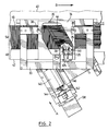
- Apparatus 10 is attached to a conventional fringe preparation table 12 by standard guide rails 14 and 16.
- Apparatus 10 includes upper and lower guide members 20 and 22 which are slidably attached to guide rails 14 and 16 and an inverted L-shaped support frame 24 which is rigidly connected to guide members 20, 22.
- the upper segment of the inverted L-shaped support frame 24 forms a base plate 26 extending across apparatus 10, and is further described below.
- Apparatus 10 is thus moveable, along guide rails 14 and 16, laterally across table 12. As is described below, apparatus 10 moves across table 12 in a series of steps wherein an unravelling cycle is performed in each step and the lateral width of each cycle is controlled by adjusting shaft collars 27.
- apparatus 10 is pneumatically driven along guide rails 14 and 16, in any suitable manner as will occur to those of skill in the art.
- any other suitable means of driving apparatus 10 can also be employed, such as stepper motors etc.
- base plate 26 is positioned to be level with the top of table 12, and is pierced by a guide channel 28, preferably running at a non-perpendicular angle across the base plate 26, as will be more fully explained below.
- a generally U-shaped upper frame 30 is fastened to base plate 26 with an open gap 32 between base plate 26 and upper frame 30.
- Upper frame 30 can be formed of several connected sections, as best seen in Figures 2 and 3, or it may be a single machined component.
- a clamping plate 34 having an opening 35, is suspended above base plate 26 by arms 36 which are attached to three pneumatically driven piston cylinders 38.
- clamping plate 34 is urged downwardly against base plate 26 by pneumatic cylinders 38, a portion of a fabric web 40 is retained in position between them, as shown in Figure 2.
- unravelling assembly 100 is mounted beneath base plate 26.
- unravelling assembly 100 includes both means of pulling one or more weft threads from the plane of the fabric and means for subsequently cutting the threads.
- threads is intended to comprise monofilament threads, fibres, etc., from which a woven fabric is formed.
- the means for pulling one or more weft threads from the plane of a fabric which comprises a vertically reciprocating unravelling needle 110, having a pointed end 106 and an inwardly cut hook 108 and the means for cutting the threads comprises a horizontally reciprocating cutter 112 mounted perpendicular to needle 110.
- Needle 110 is held at its base in a needle block 114 by a set screw 116.
- Needle block 114 is, in turn, attached to a pneumatic piston cylinder 118 which moves needle 110 towards and away from an unravelling head 120.
- a vacuum system 50 is positioned beneath base plate 26, adjacent to unravelling assembly 100 and removes from the fabric threads cut by the thread cutting means.
- Cutter 112 consists of a reciprocating blade 122 which is pneumatically driven, via hose 124, from its first position, as illustrated, towards needle 110.
- blade 122 be pneumatically driven and any other suitable drive means as will occur to those of skill in the art can be employed.
- An optical sensor 125 is fixed behind reciprocating cutter 112.
- Unravelling assembly 100 moves below base plate 26, and can be advanced by any other suitable means as will occur to those of skill in the art.
- a standard DC motor and gear assembly 134 drives a ball thread drive 136 to move unravelling assembly 100, along rails 132, in a generally longitudinal direction in relation to base plate 26 (i.e. toward or away from the weft threads).
- unravelling assembly 100 may be driven by a stepper motor 138 and a conventional lead screw assembly 140, including a lead screw 142, a lead nut 144, and spring tensioners 146.
- apparatus 10 in Figure 1 is identical to apparatus 10 in Figures 2 and 3.
- a lateral edge 42 of fabric web 40 is placed between base plate 26 and clamping plate 34 such that weft threads 44 run substantially parallel to guide rails 14 and 16, and warp threads 46 run substantially perpendicular thereto.
- weft threads 44 run substantially parallel to guide rails 14 and 16
- warp threads 46 run substantially perpendicular thereto.
- the edges of soft fabrics may have to be supported along their length to ensure that the fabric does not stretch unduly, or pull away from apparatus 10 and suitable techniques for supporting such fabricates will be apparent to those of skill in the art.
- Unravelling assembly 100 is positioned at a start position, such that edge 42 is detected by optical sensor 125.
- Sensor 125 and unravelling head 120 are separated by a preselected distance, as best seen in Figure 2. Generally, this distance will be approximately 1 to 2 inches, depending on the fabric to be fringed and this separation ensures that the weft threads in a strip 48 of fabric, running along the edge of the web 40 will remain uncut to inhibit tangling of the warp threads after the fringe is formed.
- an unravelling cycle begins.
- Clamping plate 34 is pushed downwards by cylinders 38, thereby holding a portion of web 40 taut against base plate 26, over guide channel 28 and an opening 148 in unravelling head 120 which is coincident therewith.
- Needle 110 is moved upwardly, passing through opening 148, and piercing the fabric with pointed end 106. The direction of needle 110 is then reversed, pulling it downwardly through the fabric.
- hook 108 passes through the fabric on the downward stroke, it captures one or more weft threads 44 and pulls them out of the plane of the fabric.
- Blade 122 is then advanced towards the pulled weft threads and cuts them off at the rear of the fabric and blade 122 is then retracted.
- Suction from vacuum system 50 pulls the cut portion of the weft thread, and any dust, lint or other debris from the cutting, into a vacuum container 52 to keep the work area clean.
- needle 110 can be mounted in unravelling assembly 100 by loosening set screw 116, removing needle 110, inserting a new needle and retightening set screw 116.
- the dimensions of needle 110 can be chosen to suit the nature of the woven fabric to be unravelled,. as will be apparent to those of skill in the art. The dimensions chosen can, for example, depend on thread diameter and the looseness of the weave of a particular fabric.
- the shape and size of hook 108 will also determine the number of threads to be pulled out in a single downstroke. For example, a multi-layered fabric will have weft threads in each layer which may be generally aligned, and which will be captured by relatively large hook 108 as it descends.
- unravelling assembly 100 is then moved an incremental distance along guide channel 28, in the direction of the arrow marked A in Figure 2, moving needle 110 longitudinally toward the next weft thread and the above sequence is repeated.
- the incremental step by which unravelling assembly 100 is moved is dictated by the nature of the fabric being prepared for seaming. As will be apparent to those skilled in the art, fabrics with higher weft thread densities will require smaller incremental steps for apparatus 10 than will fabrics with lower weft thread densities.
- a slight tension is also applied to the weft threads, in a direction opposite the arrow marked A in Figure 2, as the weft threads are pulled out the plane of the fabric.
- This tension is provided by spring tensioners 146 such that the captured weft thread is urged back along the warp threads to an area already unravelled. This reduces tension on, and possible deformation of the crimp in, warp threads as the weft threads are pulled out, and increases the ease with which the cut lengths of weft thread can be removed from the work area by vacuum system 50.
- Unravelling assembly 100 continues to move into fabric 40 until fringe area 54 is a preselected width along the line of the warp threads.
- the width of fringe area 54 will determine the eventual seam width, and can, for example, be in the range of from about 1 inch to about 10 inches.
- guide channel 28, in the illustrated embodiment is angled approximately 30 degrees from the line of the warp threads 46 and away from the direction of lateral travel of apparatus 10, as indicated by the arrow marked B in Figure 2.
- This angling is presently preferred as it is believed to inhibit tangling and bunching of the ends of the weft threads 44.
- the degree of angling can be chosen according to the nature of the fabric. For higher density fabrics, a greater angle may be preferred, while for low density fabrics, a smaller angle, or no angle may be preferable.
- the assembly 100 is returned to the start position, as detected by sensor 125.
- Clamping plate 34 releases the fabric portion, and apparatus 10 is then longitudinally displaced a preselected distance along guide rails 14 and 16 where the unravelling cycle is repeated.
- the distance by which apparatus 10 is moved along guide rails 14 and 16 determines the length of the cut weft threads and is set with collars 127.
- a cut length, and accordingly, a longitudinal displacement, of approximately one inch has been found to be practical for most fabrics. It will however be appreciated that the longer the cut thread, the greater the chance of damaging or stretching the warp threads. Conversely, the shorter the cut thread, the greater the number of unravelling cycles which will be required to provide a fringe area along the length of the fabric.
- the present invention allows for the automation of a previously labour intensive, manual process of fringe preparation. Fringes of any width may be prepared automatically and at great speed in comparison to manual unravelling, or previous automated systems. Once apparatus 10 is properly configured and positioned, fringe of a fabric is completed entirely autonomously.
- apparatus 10 can be turned to remove weft threads from a vertical web section.
Landscapes
- Treatment Of Fiber Materials (AREA)
- Yarns And Mechanical Finishing Of Yarns Or Ropes (AREA)
Applications Claiming Priority (2)
| Application Number | Priority Date | Filing Date | Title |
|---|---|---|---|
| US876470 | 1997-06-16 | ||
| US08/876,470 US6014797A (en) | 1997-06-16 | 1997-06-16 | Method and apparatus for unravelling threads |
Publications (3)
| Publication Number | Publication Date |
|---|---|
| EP0886003A2 true EP0886003A2 (de) | 1998-12-23 |
| EP0886003A3 EP0886003A3 (de) | 1999-01-13 |
| EP0886003B1 EP0886003B1 (de) | 2002-09-04 |
Family
ID=25367789
Family Applications (1)
| Application Number | Title | Priority Date | Filing Date |
|---|---|---|---|
| EP98304400A Expired - Lifetime EP0886003B1 (de) | 1997-06-16 | 1998-06-03 | Verfahren und Vorrichtung zum Ausriffeln von Fäden |
Country Status (5)
| Country | Link |
|---|---|
| US (1) | US6014797A (de) |
| EP (1) | EP0886003B1 (de) |
| AT (1) | ATE223533T1 (de) |
| CA (1) | CA2240657C (de) |
| DE (1) | DE69807591T2 (de) |
Cited By (1)
| Publication number | Priority date | Publication date | Assignee | Title |
|---|---|---|---|---|
| WO2005005718A1 (de) * | 2003-07-08 | 2005-01-20 | Wangner Gmbh & Co. Kg | Vorrichtung und verfahren zum entfernen einer mehrzahl parallel verlaufender fäden aus einem gewebe |
Families Citing this family (8)
| Publication number | Priority date | Publication date | Assignee | Title |
|---|---|---|---|---|
| US6731927B1 (en) | 2000-07-14 | 2004-05-04 | Context Connect, Inc. | System and method for context association |
| US7899173B2 (en) * | 2000-07-14 | 2011-03-01 | Context Connect, Llc | Communication connectivity via context association, advertising sponsorship, and multiple contact databases |
| US7340048B2 (en) * | 2000-07-14 | 2008-03-04 | Context Connect Llc | System and method for directory services and e-commerce across multi-provider networks |
| US6634068B1 (en) | 2002-04-24 | 2003-10-21 | Astenjohnson, Inc. | Apparatus for preparing a fabric for seaming |
| US7168456B1 (en) * | 2005-10-26 | 2007-01-30 | North Rocky Robot Technology, Inc. (Nortec) | Method and apparatus to remove yarns from the fringes of an industrial textile |
| DE202005018856U1 (de) * | 2005-12-01 | 2007-04-12 | Wangner Gmbh & Co Kg | Halterung für das Webblatt einer Nahtwebmaschine, um den Nahtschussfaden wahlweise mittels Schrägstellung der Riete oder verfahrbarer Rolle einzuwälzen |
| AT503434B1 (de) * | 2006-06-29 | 2007-10-15 | Wis Engineering Gmbh & Co Kg | Vorrichtung zum entfernen von schussfäden aus einem geweberand |
| FR2981091B1 (fr) * | 2011-10-06 | 2013-12-20 | Michelin Soc Tech | Dispositif et procede d'extraction de trames dans une nappe de renfort destinee a la fabrication d'un pneumatique |
Family Cites Families (19)
| Publication number | Priority date | Publication date | Assignee | Title |
|---|---|---|---|---|
| US796484A (en) * | 1905-02-01 | 1905-08-08 | Frederick H Wilms | Carpet-raveling machine. |
| US2845686A (en) * | 1955-12-02 | 1958-08-05 | F C Huyck & Sons | Apparatus and method for forming endless fabrics |
| US3413700A (en) * | 1966-12-19 | 1968-12-03 | Abowitz Alexander | Fabric unraveling machine |
| DE3025909C2 (de) * | 1980-07-09 | 1983-07-14 | Hermann Wangner Gmbh & Co Kg, 7410 Reutlingen | Verfahren und Vorrichtung zum Herstellen einer Webnaht zwischen zwei Gewebeenden |
| FI843698A0 (fi) * | 1982-08-20 | 1984-09-20 | Scapa Porritt Ltd | Automatisk hopfogningsmaskin. |
| US4581794A (en) * | 1984-03-07 | 1986-04-15 | Asten Group Inc. | Automatic seaming machine for fabric belts |
| DE3446941A1 (de) * | 1984-12-21 | 1986-07-03 | F. Oberdorfer, 7920 Heidenheim | Verfahren zur herstellung einer stecknaht zum endlosmachen eines gewebebandes und nahtungsmaschine |
| DE3507450A1 (de) * | 1985-03-02 | 1986-09-04 | Thomas Josef Heimbach GmbH & Co, 5160 Düren | Vorrichtung zum ausriffeln von faeden aus einem gewebe |
| ATE56490T1 (de) * | 1986-02-22 | 1990-09-15 | Asten Group | Automatische maschine zum verbinden zweier enden eines bandes. |
| DE3714517A1 (de) * | 1987-04-30 | 1988-11-17 | Oberdorfer Fa F | Fadentrenner fuer nahtmaschinen, insbesondere zum nahten von entwaesserungssieben, trockensieben, filzen u. dgl. |
| GB8905005D0 (en) * | 1989-03-04 | 1989-04-19 | Scapa Group Plc | Improvements in or relating to papermakers and like fabrics |
| US4972561A (en) * | 1989-12-26 | 1990-11-27 | Niagara Lockport Industries Inc. | Method of producing an angled pin seam in a papermakers felt |
| US5212858A (en) * | 1990-01-31 | 1993-05-25 | Asten Group, Inc. | Apparatus for capturing and stabilizing a yarn |
| US5027483A (en) * | 1990-01-31 | 1991-07-02 | Asten Group, Inc. | Apparatus for selectively releasing yarns from a fringe |
| US5183081A (en) * | 1992-02-07 | 1993-02-02 | Asten Group, Inc. | Weave shed formation apparatus for end reweaving type joining apparatus |
| DE9211353U1 (de) * | 1992-08-24 | 1994-01-05 | Novatech GmbH Siebe und Technologie für Papier, 72760 Reutlingen | Halterung für das Webblatt einer Nahtwebmaschine |
| DE9301722U1 (de) * | 1993-02-08 | 1994-06-09 | Novatech GmbH Siebe und Technologie für Papier, 72760 Reutlingen | Nahtwebmaschine mit Fransenfänger |
| US5390708A (en) * | 1993-09-21 | 1995-02-21 | Asten Group, Inc. | Apparatus for translating yarns in the proper position and orientation for forming a woven join |
| DE19505280C2 (de) * | 1995-02-16 | 1998-08-06 | Staeubli Gmbh | Verfahren und Vorrichtung zur maschinellen Herstellung einer Naht zum Endlosmachen einer Gewebebahn |
-
1997
- 1997-06-16 US US08/876,470 patent/US6014797A/en not_active Expired - Lifetime
-
1998
- 1998-06-03 DE DE69807591T patent/DE69807591T2/de not_active Expired - Lifetime
- 1998-06-03 EP EP98304400A patent/EP0886003B1/de not_active Expired - Lifetime
- 1998-06-03 AT AT98304400T patent/ATE223533T1/de active
- 1998-06-15 CA CA002240657A patent/CA2240657C/en not_active Expired - Lifetime
Cited By (2)
| Publication number | Priority date | Publication date | Assignee | Title |
|---|---|---|---|---|
| WO2005005718A1 (de) * | 2003-07-08 | 2005-01-20 | Wangner Gmbh & Co. Kg | Vorrichtung und verfahren zum entfernen einer mehrzahl parallel verlaufender fäden aus einem gewebe |
| DE10330958A1 (de) * | 2003-07-08 | 2005-02-03 | Wangner Finckh Gmbh & Co. Kg | Vorrichtung und Verfahren zum Entfernen einer Mehrzahl parallel verlaufender Fäden aus einem Gewebe |
Also Published As
| Publication number | Publication date |
|---|---|
| DE69807591T2 (de) | 2003-05-15 |
| CA2240657A1 (en) | 1998-12-16 |
| EP0886003A3 (de) | 1999-01-13 |
| CA2240657C (en) | 2005-08-16 |
| DE69807591D1 (de) | 2002-10-10 |
| US6014797A (en) | 2000-01-18 |
| ATE223533T1 (de) | 2002-09-15 |
| EP0886003B1 (de) | 2002-09-04 |
Similar Documents
| Publication | Publication Date | Title |
|---|---|---|
| US4581794A (en) | Automatic seaming machine for fabric belts | |
| EP0886003B1 (de) | Verfahren und Vorrichtung zum Ausriffeln von Fäden | |
| EP0663185B1 (de) | Vorrichtung zum Schneiden eines Fadens mit vorbestimmter Länge | |
| EP0316267A1 (de) | Verfahren und Vorrichtung zum Bearbeiten von textilen Materialbahnen, insbesondere zur Herstellung von Steppdecken und dgl. | |
| EP0236601B1 (de) | Automatische Maschine zum Verbinden zweier Enden eines Bandes | |
| JP2942611B2 (ja) | 経糸準備における経糸自動引込み方法と装置 | |
| US4736499A (en) | Equipment for unraveling threads from a fabric | |
| EP0052142A1 (de) | System zum herstellen blattförmiger stücke mit saumexpander. | |
| US7168456B1 (en) | Method and apparatus to remove yarns from the fringes of an industrial textile | |
| CN215800353U (zh) | 一种用于缝纫的自动勾夹线装置 | |
| EP0134214A1 (de) | Automatische bindemaschine für papiermaschinen-filzbänder | |
| EP0427665B1 (de) | Verfahren und Einrichtung zum Einziehen eines Kettfadens in eine Webmaschine, insbesondere in ein Webblatt | |
| CN219137103U (zh) | 被套自动加工设备 | |
| JP4057890B2 (ja) | ジグザグ縫いミシン | |
| US6634068B1 (en) | Apparatus for preparing a fabric for seaming | |
| KR930004076B1 (ko) | 절단 경사에 대한 바디(筬)위치 검출방법 및 위치 제어장치 | |
| US4714035A (en) | Placket lining machine | |
| US4938157A (en) | Computerized numerical control automatic sewing device | |
| CN115748113B (zh) | 被套自动加工设备 | |
| CA1230012A (en) | Placket lining machine | |
| KR930004078B1 (ko) | 수복(修腹)후의 경사의 처리방법 | |
| CN221760116U (zh) | 一种编织机 | |
| JPH02210045A (ja) | たて糸自動補修方法 | |
| CN101583750A (zh) | 水平多针绗缝机及绗缝方法 | |
| CA2010539A1 (en) | Method and apparatus for testing sewing thread |
Legal Events
| Date | Code | Title | Description |
|---|---|---|---|
| PUAI | Public reference made under article 153(3) epc to a published international application that has entered the european phase |
Free format text: ORIGINAL CODE: 0009012 |
|
| PUAL | Search report despatched |
Free format text: ORIGINAL CODE: 0009013 |
|
| AK | Designated contracting states |
Kind code of ref document: A2 Designated state(s): AT BE CH DE ES FI FR GB IT LI SE |
|
| AX | Request for extension of the european patent |
Free format text: AL;LT;LV;MK;RO;SI |
|
| AK | Designated contracting states |
Kind code of ref document: A3 Designated state(s): AT BE CH CY DE DK ES FI FR GB GR IE IT LI LU MC NL PT SE |
|
| AX | Request for extension of the european patent |
Free format text: AL;LT;LV;MK;RO;SI |
|
| 17P | Request for examination filed |
Effective date: 19990706 |
|
| AKX | Designation fees paid |
Free format text: AT BE CH DE ES FI FR GB IT LI SE |
|
| 17Q | First examination report despatched |
Effective date: 20000724 |
|
| GRAG | Despatch of communication of intention to grant |
Free format text: ORIGINAL CODE: EPIDOS AGRA |
|
| GRAG | Despatch of communication of intention to grant |
Free format text: ORIGINAL CODE: EPIDOS AGRA |
|
| GRAH | Despatch of communication of intention to grant a patent |
Free format text: ORIGINAL CODE: EPIDOS IGRA |
|
| GRAH | Despatch of communication of intention to grant a patent |
Free format text: ORIGINAL CODE: EPIDOS IGRA |
|
| GRAA | (expected) grant |
Free format text: ORIGINAL CODE: 0009210 |
|
| AK | Designated contracting states |
Kind code of ref document: B1 Designated state(s): AT BE CH DE ES FI FR GB IT LI SE |
|
| PG25 | Lapsed in a contracting state [announced via postgrant information from national office to epo] |
Ref country code: IT Free format text: LAPSE BECAUSE OF FAILURE TO SUBMIT A TRANSLATION OF THE DESCRIPTION OR TO PAY THE FEE WITHIN THE PRE;WARNING: LAPSES OF ITALIAN PATENTS WITH EFFECTIVE DATE BEFORE 2007 MAY HAVE OCCURRED AT ANY TIME BEFORE 2007. THE CORRECT EFFECTIVE DATE MAY BE DIFFERENT FROM THE ONE RECORDED.SCRIBED TIME-LIMIT Effective date: 20020904 |
|
| REF | Corresponds to: |
Ref document number: 223533 Country of ref document: AT Date of ref document: 20020915 Kind code of ref document: T |
|
| REG | Reference to a national code |
Ref country code: GB Ref legal event code: FG4D |
|
| REG | Reference to a national code |
Ref country code: CH Ref legal event code: EP |
|
| REF | Corresponds to: |
Ref document number: 69807591 Country of ref document: DE Date of ref document: 20021010 |
|
| REG | Reference to a national code |
Ref country code: CH Ref legal event code: NV Representative=s name: AMMANN PATENTANWAELTE AG BERN |
|
| ET | Fr: translation filed | ||
| PG25 | Lapsed in a contracting state [announced via postgrant information from national office to epo] |
Ref country code: ES Free format text: LAPSE BECAUSE OF FAILURE TO SUBMIT A TRANSLATION OF THE DESCRIPTION OR TO PAY THE FEE WITHIN THE PRESCRIBED TIME-LIMIT Effective date: 20030328 |
|
| PLBQ | Unpublished change to opponent data |
Free format text: ORIGINAL CODE: EPIDOS OPPO |
|
| PLBI | Opposition filed |
Free format text: ORIGINAL CODE: 0009260 |
|
| PLAX | Notice of opposition and request to file observation + time limit sent |
Free format text: ORIGINAL CODE: EPIDOSNOBS2 |
|
| 26 | Opposition filed |
Opponent name: WANGNER FINCKH GMBH & CO. KG Effective date: 20030603 |
|
| PLAX | Notice of opposition and request to file observation + time limit sent |
Free format text: ORIGINAL CODE: EPIDOSNOBS2 |
|
| PLBB | Reply of patent proprietor to notice(s) of opposition received |
Free format text: ORIGINAL CODE: EPIDOSNOBS3 |
|
| PLAB | Opposition data, opponent's data or that of the opponent's representative modified |
Free format text: ORIGINAL CODE: 0009299OPPO |
|
| R26 | Opposition filed (corrected) |
Opponent name: WANGNER GMBH & CO. KG Effective date: 20030603 |
|
| RAP2 | Party data changed (patent owner data changed or rights of a patent transferred) |
Owner name: ASTENJOHNSON, INC. |
|
| REG | Reference to a national code |
Ref country code: CH Ref legal event code: PUE Owner name: ASTENJOHNSON, INC. Free format text: JWI LIMITED#48 RICHARDSON ROAD#KANATA ONTARIO K2K 1X2 (CA) -TRANSFER TO- ASTENJOHNSON, INC.#48 RICHARDSON ROAD#KANATA, ONTARIO K2K 1X2 (CA) |
|
| PGFP | Annual fee paid to national office [announced via postgrant information from national office to epo] |
Ref country code: BE Payment date: 20050526 Year of fee payment: 8 |
|
| PGFP | Annual fee paid to national office [announced via postgrant information from national office to epo] |
Ref country code: SE Payment date: 20050607 Year of fee payment: 8 |
|
| PGFP | Annual fee paid to national office [announced via postgrant information from national office to epo] |
Ref country code: FI Payment date: 20050620 Year of fee payment: 8 |
|
| PGFP | Annual fee paid to national office [announced via postgrant information from national office to epo] |
Ref country code: CH Payment date: 20050629 Year of fee payment: 8 |
|
| PLCK | Communication despatched that opposition was rejected |
Free format text: ORIGINAL CODE: EPIDOSNREJ1 |
|
| APBP | Date of receipt of notice of appeal recorded |
Free format text: ORIGINAL CODE: EPIDOSNNOA2O |
|
| APAH | Appeal reference modified |
Free format text: ORIGINAL CODE: EPIDOSCREFNO |
|
| REG | Reference to a national code |
Ref country code: CH Ref legal event code: PUE Owner name: NORTEC, INC. Free format text: ASTENJOHNSON, INC.#48 RICHARDSON ROAD#KANATA, ONTARIO K2K 1X2 (CA) -TRANSFER TO- NORTEC, INC.#1305 HIGHWAY 2 WEST#SANDPOINT, ID 83864 (US) |
|
| REG | Reference to a national code |
Ref country code: GB Ref legal event code: 732E |
|
| APBQ | Date of receipt of statement of grounds of appeal recorded |
Free format text: ORIGINAL CODE: EPIDOSNNOA3O |
|
| PG25 | Lapsed in a contracting state [announced via postgrant information from national office to epo] |
Ref country code: FI Free format text: LAPSE BECAUSE OF NON-PAYMENT OF DUE FEES Effective date: 20060603 |
|
| PG25 | Lapsed in a contracting state [announced via postgrant information from national office to epo] |
Ref country code: SE Free format text: LAPSE BECAUSE OF NON-PAYMENT OF DUE FEES Effective date: 20060604 |
|
| PG25 | Lapsed in a contracting state [announced via postgrant information from national office to epo] |
Ref country code: LI Free format text: LAPSE BECAUSE OF NON-PAYMENT OF DUE FEES Effective date: 20060630 Ref country code: CH Free format text: LAPSE BECAUSE OF NON-PAYMENT OF DUE FEES Effective date: 20060630 Ref country code: BE Free format text: LAPSE BECAUSE OF NON-PAYMENT OF DUE FEES Effective date: 20060630 |
|
| REG | Reference to a national code |
Ref country code: GB Ref legal event code: 732E |
|
| REG | Reference to a national code |
Ref country code: FR Ref legal event code: TP |
|
| REG | Reference to a national code |
Ref country code: CH Ref legal event code: PL |
|
| EUG | Se: european patent has lapsed | ||
| APAH | Appeal reference modified |
Free format text: ORIGINAL CODE: EPIDOSCREFNO |
|
| BERE | Be: lapsed |
Owner name: *JWI LTD Effective date: 20060630 |
|
| APBU | Appeal procedure closed |
Free format text: ORIGINAL CODE: EPIDOSNNOA9O |
|
| PLBN | Opposition rejected |
Free format text: ORIGINAL CODE: 0009273 |
|
| STAA | Information on the status of an ep patent application or granted ep patent |
Free format text: STATUS: OPPOSITION REJECTED |
|
| 27O | Opposition rejected |
Effective date: 20080813 |
|
| PGFP | Annual fee paid to national office [announced via postgrant information from national office to epo] |
Ref country code: FR Payment date: 20120705 Year of fee payment: 15 Ref country code: GB Payment date: 20120601 Year of fee payment: 15 |
|
| GBPC | Gb: european patent ceased through non-payment of renewal fee |
Effective date: 20130603 |
|
| REG | Reference to a national code |
Ref country code: FR Ref legal event code: ST Effective date: 20140228 |
|
| PG25 | Lapsed in a contracting state [announced via postgrant information from national office to epo] |
Ref country code: GB Free format text: LAPSE BECAUSE OF NON-PAYMENT OF DUE FEES Effective date: 20130603 |
|
| PG25 | Lapsed in a contracting state [announced via postgrant information from national office to epo] |
Ref country code: FR Free format text: LAPSE BECAUSE OF NON-PAYMENT OF DUE FEES Effective date: 20130701 |
|
| PGFP | Annual fee paid to national office [announced via postgrant information from national office to epo] |
Ref country code: AT Payment date: 20160621 Year of fee payment: 19 |
|
| PGFP | Annual fee paid to national office [announced via postgrant information from national office to epo] |
Ref country code: DE Payment date: 20170810 Year of fee payment: 20 |
|
| REG | Reference to a national code |
Ref country code: AT Ref legal event code: MM01 Ref document number: 223533 Country of ref document: AT Kind code of ref document: T Effective date: 20170603 |
|
| PG25 | Lapsed in a contracting state [announced via postgrant information from national office to epo] |
Ref country code: AT Free format text: LAPSE BECAUSE OF NON-PAYMENT OF DUE FEES Effective date: 20170603 |
|
| REG | Reference to a national code |
Ref country code: DE Ref legal event code: R071 Ref document number: 69807591 Country of ref document: DE |