EP0885841B1 - System and method for collecting and refining SF6 gas - Google Patents
System and method for collecting and refining SF6 gas Download PDFInfo
- Publication number
- EP0885841B1 EP0885841B1 EP98111045A EP98111045A EP0885841B1 EP 0885841 B1 EP0885841 B1 EP 0885841B1 EP 98111045 A EP98111045 A EP 98111045A EP 98111045 A EP98111045 A EP 98111045A EP 0885841 B1 EP0885841 B1 EP 0885841B1
- Authority
- EP
- European Patent Office
- Prior art keywords
- gas
- filter
- collecting
- refining
- compressor
- Prior art date
- Legal status (The legal status is an assumption and is not a legal conclusion. Google has not performed a legal analysis and makes no representation as to the accuracy of the status listed.)
- Revoked
Links
- 238000007670 refining Methods 0.000 title claims description 69
- 238000000034 method Methods 0.000 title claims description 51
- 239000007789 gas Substances 0.000 claims description 420
- 230000002378 acidificating effect Effects 0.000 claims description 36
- 239000000203 mixture Substances 0.000 claims description 26
- CURLTUGMZLYLDI-UHFFFAOYSA-N Carbon dioxide Chemical compound O=C=O CURLTUGMZLYLDI-UHFFFAOYSA-N 0.000 claims description 20
- 230000008569 process Effects 0.000 claims description 20
- 239000003463 adsorbent Substances 0.000 claims description 17
- 239000012535 impurity Substances 0.000 claims description 12
- 229910002092 carbon dioxide Inorganic materials 0.000 claims description 11
- 239000001569 carbon dioxide Substances 0.000 claims description 9
- QVGXLLKOCUKJST-UHFFFAOYSA-N atomic oxygen Chemical compound [O] QVGXLLKOCUKJST-UHFFFAOYSA-N 0.000 claims description 8
- 239000001301 oxygen Substances 0.000 claims description 8
- 229910052760 oxygen Inorganic materials 0.000 claims description 8
- 239000006227 byproduct Substances 0.000 claims description 7
- IJGRMHOSHXDMSA-UHFFFAOYSA-N Atomic nitrogen Chemical compound N#N IJGRMHOSHXDMSA-UHFFFAOYSA-N 0.000 claims description 4
- 238000001816 cooling Methods 0.000 claims description 4
- 238000012935 Averaging Methods 0.000 claims description 3
- 239000003513 alkali Substances 0.000 claims description 3
- OYPRJOBELJOOCE-UHFFFAOYSA-N Calcium Chemical group [Ca] OYPRJOBELJOOCE-UHFFFAOYSA-N 0.000 claims description 2
- 229910052757 nitrogen Inorganic materials 0.000 claims description 2
- 230000003472 neutralizing effect Effects 0.000 description 26
- 239000003795 chemical substances by application Substances 0.000 description 25
- 238000012545 processing Methods 0.000 description 16
- OKTJSMMVPCPJKN-UHFFFAOYSA-N Carbon Chemical compound [C] OKTJSMMVPCPJKN-UHFFFAOYSA-N 0.000 description 13
- 230000003247 decreasing effect Effects 0.000 description 13
- AXCZMVOFGPJBDE-UHFFFAOYSA-L calcium dihydroxide Chemical compound [OH-].[OH-].[Ca+2] AXCZMVOFGPJBDE-UHFFFAOYSA-L 0.000 description 10
- 239000000920 calcium hydroxide Substances 0.000 description 9
- 229910001861 calcium hydroxide Inorganic materials 0.000 description 9
- 238000010276 construction Methods 0.000 description 9
- 238000010586 diagram Methods 0.000 description 9
- 238000007689 inspection Methods 0.000 description 9
- 239000012071 phase Substances 0.000 description 7
- 239000012670 alkaline solution Substances 0.000 description 6
- 238000005259 measurement Methods 0.000 description 6
- 238000005070 sampling Methods 0.000 description 6
- 238000012423 maintenance Methods 0.000 description 5
- 238000010792 warming Methods 0.000 description 5
- 239000002699 waste material Substances 0.000 description 5
- 239000002351 wastewater Substances 0.000 description 5
- 230000008859 change Effects 0.000 description 4
- 230000007423 decrease Effects 0.000 description 4
- 238000013461 design Methods 0.000 description 4
- 239000007787 solid Substances 0.000 description 4
- 239000000126 substance Substances 0.000 description 4
- 239000007864 aqueous solution Substances 0.000 description 3
- 150000002222 fluorine compounds Chemical class 0.000 description 3
- 238000010438 heat treatment Methods 0.000 description 3
- 238000009434 installation Methods 0.000 description 3
- 239000002808 molecular sieve Substances 0.000 description 3
- URGAHOPLAPQHLN-UHFFFAOYSA-N sodium aluminosilicate Chemical compound [Na+].[Al+3].[O-][Si]([O-])=O.[O-][Si]([O-])=O URGAHOPLAPQHLN-UHFFFAOYSA-N 0.000 description 3
- 239000000243 solution Substances 0.000 description 3
- 238000012360 testing method Methods 0.000 description 3
- XLYOFNOQVPJJNP-UHFFFAOYSA-N water Substances O XLYOFNOQVPJJNP-UHFFFAOYSA-N 0.000 description 3
- PXHVJJICTQNCMI-UHFFFAOYSA-N Nickel Chemical compound [Ni] PXHVJJICTQNCMI-UHFFFAOYSA-N 0.000 description 2
- 229910021536 Zeolite Inorganic materials 0.000 description 2
- 230000008901 benefit Effects 0.000 description 2
- 238000012790 confirmation Methods 0.000 description 2
- HNPSIPDUKPIQMN-UHFFFAOYSA-N dioxosilane;oxo(oxoalumanyloxy)alumane Chemical compound O=[Si]=O.O=[Al]O[Al]=O HNPSIPDUKPIQMN-UHFFFAOYSA-N 0.000 description 2
- 238000007599 discharging Methods 0.000 description 2
- 230000000694 effects Effects 0.000 description 2
- 239000000945 filler Substances 0.000 description 2
- 229910001512 metal fluoride Inorganic materials 0.000 description 2
- 238000007747 plating Methods 0.000 description 2
- 238000001179 sorption measurement Methods 0.000 description 2
- 150000003568 thioethers Chemical class 0.000 description 2
- LSJNBGSOIVSBBR-UHFFFAOYSA-N thionyl fluoride Chemical compound FS(F)=O LSJNBGSOIVSBBR-UHFFFAOYSA-N 0.000 description 2
- 238000012546 transfer Methods 0.000 description 2
- 238000011144 upstream manufacturing Methods 0.000 description 2
- 125000000391 vinyl group Chemical group [H]C([*])=C([H])[H] 0.000 description 2
- 229920002554 vinyl polymer Polymers 0.000 description 2
- 239000010457 zeolite Substances 0.000 description 2
- KRHYYFGTRYWZRS-UHFFFAOYSA-M Fluoride anion Chemical compound [F-] KRHYYFGTRYWZRS-UHFFFAOYSA-M 0.000 description 1
- LSNNMFCWUKXFEE-UHFFFAOYSA-N Sulfurous acid Chemical compound OS(O)=O LSNNMFCWUKXFEE-UHFFFAOYSA-N 0.000 description 1
- RAHZWNYVWXNFOC-UHFFFAOYSA-N Sulphur dioxide Chemical compound O=S=O RAHZWNYVWXNFOC-UHFFFAOYSA-N 0.000 description 1
- 208000027418 Wounds and injury Diseases 0.000 description 1
- 239000002250 absorbent Substances 0.000 description 1
- 230000002745 absorbent Effects 0.000 description 1
- 239000002253 acid Substances 0.000 description 1
- 239000002585 base Substances 0.000 description 1
- 230000005587 bubbling Effects 0.000 description 1
- 239000011575 calcium Substances 0.000 description 1
- 159000000007 calcium salts Chemical class 0.000 description 1
- 150000003841 chloride salts Chemical class 0.000 description 1
- 238000007796 conventional method Methods 0.000 description 1
- 230000006378 damage Effects 0.000 description 1
- 238000010891 electric arc Methods 0.000 description 1
- 238000005516 engineering process Methods 0.000 description 1
- 238000004880 explosion Methods 0.000 description 1
- 239000012530 fluid Substances 0.000 description 1
- 230000003301 hydrolyzing effect Effects 0.000 description 1
- 208000014674 injury Diseases 0.000 description 1
- 239000011810 insulating material Substances 0.000 description 1
- 238000009413 insulation Methods 0.000 description 1
- 239000007791 liquid phase Substances 0.000 description 1
- 239000010808 liquid waste Substances 0.000 description 1
- 238000012986 modification Methods 0.000 description 1
- 230000004048 modification Effects 0.000 description 1
- 238000012544 monitoring process Methods 0.000 description 1
- 229910052759 nickel Inorganic materials 0.000 description 1
- 238000005457 optimization Methods 0.000 description 1
- 239000002245 particle Substances 0.000 description 1
- 230000002265 prevention Effects 0.000 description 1
- 230000009467 reduction Effects 0.000 description 1
- 150000003839 salts Chemical class 0.000 description 1
- 229920006395 saturated elastomer Polymers 0.000 description 1
- 238000000926 separation method Methods 0.000 description 1
- 238000004513 sizing Methods 0.000 description 1
- 238000003756 stirring Methods 0.000 description 1
- QHMQWEPBXSHHLH-UHFFFAOYSA-N sulfur tetrafluoride Chemical compound FS(F)(F)F QHMQWEPBXSHHLH-UHFFFAOYSA-N 0.000 description 1
- OBTWBSRJZRCYQV-UHFFFAOYSA-N sulfuryl difluoride Chemical compound FS(F)(=O)=O OBTWBSRJZRCYQV-UHFFFAOYSA-N 0.000 description 1
- 238000004804 winding Methods 0.000 description 1
Images


Classifications
-
- B—PERFORMING OPERATIONS; TRANSPORTING
- B01—PHYSICAL OR CHEMICAL PROCESSES OR APPARATUS IN GENERAL
- B01D—SEPARATION
- B01D46/00—Filters or filtering processes specially modified for separating dispersed particles from gases or vapours
- B01D46/54—Particle separators, e.g. dust precipitators, using ultra-fine filter sheets or diaphragms
- B01D46/543—Particle separators, e.g. dust precipitators, using ultra-fine filter sheets or diaphragms using membranes
-
- C—CHEMISTRY; METALLURGY
- C01—INORGANIC CHEMISTRY
- C01B—NON-METALLIC ELEMENTS; COMPOUNDS THEREOF; METALLOIDS OR COMPOUNDS THEREOF NOT COVERED BY SUBCLASS C01C
- C01B17/00—Sulfur; Compounds thereof
- C01B17/45—Compounds containing sulfur and halogen, with or without oxygen
- C01B17/4507—Compounds containing sulfur and halogen, with or without oxygen containing sulfur and halogen only
- C01B17/4515—Compounds containing sulfur and halogen, with or without oxygen containing sulfur and halogen only containing sulfur and fluorine only
- C01B17/453—Sulfur hexafluoride
-
- B—PERFORMING OPERATIONS; TRANSPORTING
- B01—PHYSICAL OR CHEMICAL PROCESSES OR APPARATUS IN GENERAL
- B01D—SEPARATION
- B01D46/00—Filters or filtering processes specially modified for separating dispersed particles from gases or vapours
- B01D46/0027—Filters or filtering processes specially modified for separating dispersed particles from gases or vapours with additional separating or treating functions
- B01D46/0036—Filters or filtering processes specially modified for separating dispersed particles from gases or vapours with additional separating or treating functions by adsorption or absorption
-
- B—PERFORMING OPERATIONS; TRANSPORTING
- B01—PHYSICAL OR CHEMICAL PROCESSES OR APPARATUS IN GENERAL
- B01D—SEPARATION
- B01D46/00—Filters or filtering processes specially modified for separating dispersed particles from gases or vapours
- B01D46/42—Auxiliary equipment or operation thereof
- B01D46/4272—Special valve constructions adapted to filters or filter elements
-
- B—PERFORMING OPERATIONS; TRANSPORTING
- B01—PHYSICAL OR CHEMICAL PROCESSES OR APPARATUS IN GENERAL
- B01D—SEPARATION
- B01D46/00—Filters or filtering processes specially modified for separating dispersed particles from gases or vapours
- B01D46/42—Auxiliary equipment or operation thereof
- B01D46/44—Auxiliary equipment or operation thereof controlling filtration
- B01D46/442—Auxiliary equipment or operation thereof controlling filtration by measuring the concentration of particles
-
- B—PERFORMING OPERATIONS; TRANSPORTING
- B01—PHYSICAL OR CHEMICAL PROCESSES OR APPARATUS IN GENERAL
- B01D—SEPARATION
- B01D53/00—Separation of gases or vapours; Recovering vapours of volatile solvents from gases; Chemical or biological purification of waste gases, e.g. engine exhaust gases, smoke, fumes, flue gases, aerosols
- B01D53/34—Chemical or biological purification of waste gases
- B01D53/46—Removing components of defined structure
- B01D53/68—Halogens or halogen compounds
- B01D53/685—Halogens or halogen compounds by treating the gases with solids
-
- H—ELECTRICITY
- H01—ELECTRIC ELEMENTS
- H01H—ELECTRIC SWITCHES; RELAYS; SELECTORS; EMERGENCY PROTECTIVE DEVICES
- H01H33/00—High-tension or heavy-current switches with arc-extinguishing or arc-preventing means
- H01H33/02—Details
- H01H33/53—Cases; Reservoirs, tanks, piping or valves, for arc-extinguishing fluid; Accessories therefor, e.g. safety arrangements, pressure relief devices
- H01H33/56—Gas reservoirs
-
- H—ELECTRICITY
- H02—GENERATION; CONVERSION OR DISTRIBUTION OF ELECTRIC POWER
- H02B—BOARDS, SUBSTATIONS OR SWITCHING ARRANGEMENTS FOR THE SUPPLY OR DISTRIBUTION OF ELECTRIC POWER
- H02B13/00—Arrangement of switchgear in which switches are enclosed in, or structurally associated with, a casing, e.g. cubicle
- H02B13/02—Arrangement of switchgear in which switches are enclosed in, or structurally associated with, a casing, e.g. cubicle with metal casing
- H02B13/035—Gas-insulated switchgear
- H02B13/055—Features relating to the gas
-
- Y—GENERAL TAGGING OF NEW TECHNOLOGICAL DEVELOPMENTS; GENERAL TAGGING OF CROSS-SECTIONAL TECHNOLOGIES SPANNING OVER SEVERAL SECTIONS OF THE IPC; TECHNICAL SUBJECTS COVERED BY FORMER USPC CROSS-REFERENCE ART COLLECTIONS [XRACs] AND DIGESTS
- Y02—TECHNOLOGIES OR APPLICATIONS FOR MITIGATION OR ADAPTATION AGAINST CLIMATE CHANGE
- Y02C—CAPTURE, STORAGE, SEQUESTRATION OR DISPOSAL OF GREENHOUSE GASES [GHG]
- Y02C20/00—Capture or disposal of greenhouse gases
- Y02C20/30—Capture or disposal of greenhouse gases of perfluorocarbons [PFC], hydrofluorocarbons [HFC] or sulfur hexafluoride [SF6]
-
- Y—GENERAL TAGGING OF NEW TECHNOLOGICAL DEVELOPMENTS; GENERAL TAGGING OF CROSS-SECTIONAL TECHNOLOGIES SPANNING OVER SEVERAL SECTIONS OF THE IPC; TECHNICAL SUBJECTS COVERED BY FORMER USPC CROSS-REFERENCE ART COLLECTIONS [XRACs] AND DIGESTS
- Y02—TECHNOLOGIES OR APPLICATIONS FOR MITIGATION OR ADAPTATION AGAINST CLIMATE CHANGE
- Y02P—CLIMATE CHANGE MITIGATION TECHNOLOGIES IN THE PRODUCTION OR PROCESSING OF GOODS
- Y02P20/00—Technologies relating to chemical industry
- Y02P20/151—Reduction of greenhouse gas [GHG] emissions, e.g. CO2
Definitions
- the present invention relates to a system for collecting and refining SF 6 gas at maintenance and inspection of an insulated machine using SF 6 gas as an insulating gas and a method therefor and, more particularly, to a system for collecting and refining SF 6 gas and a method therefor suitable for recovering a deteriorated SF 6 gas by collecting and refining.
- SF 6 gas which is an inflammable insulating gas.
- transformers have employed an insulating oil as the insulating material, but an inflammable insulating gas is used instead of the insulating oil because the insulating oil has a probability of occurrence of fire or explosion in a case of trouble.
- SF 6 gas is widely used as the insulating gas.
- SF 6 gas has a global warming property (hereinafter referred to as GWP) coefficient as large as approximately 25000 and accordingly has a large effect to the global warming. Therefore, from the viewpoint of global warming prevention, it is preferable to prevent SF 6 gas, even a small quantity, from discharging to atmosphere.
- GWP global warming property
- the density of SF 6 gas is approximately five times as large as that of air, there is a possibility to cause an accident resulting in injury or death by an oxygen shortage when SF 6 gas is discharged inside a room because it stagnates in the bottom portion of the room or the lowermost portion of the building.
- SF 6 gas is partly decomposed during using by arc discharge or the like, and part of the discomposed compositions react with moisture to produce acidic gases. Therefore, by-product refining gases are produced. That is, as shown in Table 1, SF 6 gas is partly decomposed by discharge or arc to produce acidic gases and metal fluorides such as HF, SOF 2 , SO 2 , H 2 SO 3 , SF 4 , SF 2 , S 2 F 2 and so on.
- metal fluorides such as HF, SOF 2 , SO 2 , H 2 SO 3 , SF 4 , SF 2 , S 2 F 2 and so on.
- a method of collecting and bringing back SF 6 gas and refining the SF 6 gas to be reused is proposed.
- a decomposed gas treating system for a SF 6 gas insulated electric machine is disclosed in Japanese Patent Application Laid-Open No.9-856 proposes a method in which acidic gases among by-product gases contained in a deteriorated used SF 6 gas is removed by bubbling in an alkaline solution and then the SF 6 gas is filled in a compressed-gas cylinder to be brought back and refine the SF 6 gas.
- SF 6 gas is an important factor to dominate the insulation performance of a gas insulated transformer or a gas insulated switch-gear. Therefore, in order to refine and reuse the SF 6 gas, it is required to confirm that the performance of the recovered SF 6 gas is equivalent to that of new SF 6 gas. If the recovered SF 6 gas contains impurities and the insulating performance is degraded, the apparatus is broken and damaged by occurrence of a short circuit inside the apparatus. Therefore, the collection and refinement requires confirmation by measuring the property of the recovered SF 6 gas. Table 3 shows an analysis result of an SF 6 gas used in a gas insulated switch-gear after repeating to open and close.
- the gas insulated machine can be made small in size compared to that of the conventional method, the gas insulated machine in a substation in a town is usually installed in a basement form the viewpoint of effective use of the site area.
- the gas insulating method has less fire potential compared to the conventional oil insulating method in addition to the advantage of small size, gas insulated machines are widely employed.
- the gas insulated machine capable of reducing the installation area is advantageous even in such a case.
- the gas insulated machines are distributedly installed in many sites as described above, it is required that the system for collecting and refining the SF 6 gas to reuse it is small and portable. If the system for collecting and refining is not small and portable, it is required to fill the collected gas into a compressed gas-cylinder and to transfer it to a place where a refining apparatus is installed and then after refining to transfer it to the site again. Therefore, time period of the inspection process is lengthened and work for carrying in and out the compressed-gas cylinder is necessary.
- the conventional SF 6 gas collecting system Since the conventional SF 6 gas collecting system has only a gas collecting function but not a gas refining function, the conventional SF 6 gas collecting system is designed based on the viewpoint of how fast SF 6 gas is collected from a gas insulated machine in order to improve work efficiency.
- SF 6 gas When SF 6 gas is filled in a gas insulated machine, for example, at a pressure of 5 kg/cm 2 , the SF 6 gas is firstly collected into a collecting tank until pressure of the collecting tank and pressure of the gas insulated machine becomes equilibrium by opening a communicating pipe line, and then the remaining SF 6 gas is collected into the collecting tank using a compressor or a vacuum pump.
- pressure of the machine side is decreased from 5 kg/cm 2 to approximately 3 kg/cm 2 within a 1 to 2 minutes after opening the communicating pipe line. Then, the remaining SF 6 gas is collected using the compressor. However, approximately 1/3 of the gas has been collected by the opening of the communicating pipe line. Since an efficiency of the compressor decreases as the pressure in the machine side is decreased, an amount of collecting gas per unit time is decreased as the compressor is operated and the amount of collecting gas per unit time becomes the minimum at the end of the collecting work.
- the refining process system needs to be designed so as to meet to the maximum processing gas flow rate.
- design of the system of the wet method is performed by determining a used amount of alkaline solution to a unit volume of the treated gas (ratio of solution to gas) to a predetermined value.
- design is also performed by determining a ratio of the treated gas volume treated in unit time to a volume of an adsorption removing agent (SV value).
- the system needs to be designed so as to meet to the maximum gas flow rate when the processed gas rate varies, which leads to problems in that the system becomes large in size and consequently optimization and small-sizing of the system cannot be attained. Further, when the gas flow rate exceeds a value of design condition, a large amount of the alkaline solution is carried over by the gas in a case of the wet method to cause a trouble in the following process. Furthermore, regardless of the dry method or the wet method, there occurs a problem in that the initial removing performance cannot be attained.
- a first object of the present invention is to provide a system for collecting and refining SF 6 gas and a method of collecting and refining SF 6 gas which are small-sized and easy-operable in collection and refinement of SF 6 gas from an SF 6 gas insulated machine.
- a second object of the present invention is to provide a system for collecting and refining SF 6 gas and a method of collecting and refining SF 6 gas which are capable of measuring and confirming compositions of SF 6 gas and capable of reusing the SF 6 gas in a short time at a working site of the SF 6 gas collecting and refining processing.
- a system for collecting and refining SF 6 gas in accordance with the present invention is characterized by comprising a first filter connected to a gas insulated machine; a constant flow rate supplier connected to a downstream side of the first filter; a compressor and a vacuum pump connected in parallel to a downstream side of the constant flow rate supplier; a collecting tank connected to a downstream side of the compressor; and a cooler for cooling the collecting tank, wherein the first filter is constructed by a filter filled with a dry adsorbent.
- system for collecting and refining SF 6 gas is characterized by further comprising a constant flow rate valve arranged in an inlet side of said compressor.
- a method of collecting and refining SF 6 gas in accordance with the present invention is characterized by comprising the steps of removing impurities from SF 6 gas from a gas insulated machine by averaging a flow rate of the SF 6 gas and letting the SF 6 gas flow through a first filter filled with a dry adsorbent; adsorbing and removing by-product gases by a second filter filled with a dry adsorbent; and collecting the SF 6 gas separated by the second filter by cooling and liquefying the SF 6 gas.
- a system for collecting and refining SF 6 gas in accordance with the present invention is characterized by comprising at least a second filter arranged between the compressor and the collecting tank; and an analysis equipment including a gaschromatograph in a downstream side of the second filter.
- a method of collecting and refining SF 6 gas in accordance with the present invention is characterized by comprising the step of confirming compositions of the collected SF 6 gas by analyzing composition analysis items of moisture concentration, acidic gas concentration, carbon dioxide concentration, oxygen or nitrogen concentration and PFC concentration, and repeating the process of confirming said compositions and a process of returning the collected SF 6 gas to the first filter until the compositions become preset values.
- FIG. 1 is a diagram showing the construction of a first embodiment of the system for collecting and refining SF 6 gas.
- FIG. 2 is a graph showing the relationship between collecting processing time and compressor inlet pressure.
- FIG. 3 is a graph showing the relationship between collecting processing time and collecting and processing rate of insulating gas.
- the system for collecting and refining SF 6 gas of this embodiment is constructed as follows. As shown in FIG. 1, a gas insulated machine 1 is connected to a first filter 4 through a dividing valve 2 and a dividing three-way valve 3. An insulating gas, SF 6 ,of 10 m 3 at 5 kg/cm 2 is filled in the gas insulated machine 1.
- the first filter 4 is connected to a second filter 8 through a constant flow rate supplier 5 and a compressor 6.
- a vacuum pump 7a and a by-pass pipe 7b are arranged between the constant flow rate supplier 5 and the compressor 6 in parallel, and a flow path of the vacuum pump 7a or the by-pass pipe 7b is selected through a three-way valve 7c.
- the three-way valve 7c connects the constant flow rate supplier 5 and the compressor 6 through the by-pass pipe 7b in the initial stage of operation, and connects the constant flow rate supplier 5 and the compressor 6 through the vacuum pump 7a when the pressure in the gas insulated machine 1 is decreased.
- a pressure reducing valve is used as the constant flow rate supplier 5.
- the second filter 8 is connected to a third filter 9.
- the third filter 9 is connected to a collecting tank 10 having a cooler 20, and the collecting tank 10 is connected to a sampling header 13 through a sampling position switching valve 11 and a pressure reducing valve 12.
- the sampling header 13 is connected to an analysis equipment 14 and also connected to a flow meter 16 through an exhaust gas valve 15.
- the analysis equipment 14 and the flow meter 16 are connected to each other in the downstream of the exhaust gas valve 15.
- the flow meter 16 is connected to an exhaust filter 17.
- the collecting tank 10 is connected to the dividing three-way valve 3 through a discharge valve 18 and a heater 19, and a branch portion is arranged between the heater 19 and the three-way valve 3, and the branch portion is connected to the sampling position switching valve 11.
- a deteriorated insulating gas in the gas insulated machine 1 is supplied to the first filter through the three-way valve by opening the dividing valve 2.
- the pressure reducing valve as the constant flow rate supplier 5 is fully closed.
- the pressure reducing valve is gradually opened and controlled so that the outlet pressure of the pressure reducing valve becomes 1.5 kg/cm 2 .
- the compressor 6 is started to operate to start collecting of the SF 6 gas.
- the pressure reducing valve is controlled so as to maintain the inlet pressure of the compressor to 1.5 kg/cm 2 , the collecting capacity of the compressor 6 is maintained at a constant value. Therefore, the collecting and processing rate of the SF 6 gas can be maintained to a constant value. Thereby, required amounts of adsorbent, neutralizer and the like can be minimized to necessary and minimum values.
- the collecting amount of the SF 6 gas per unit time in the initial stage is set to 1 N m 3 /min.
- a fluid resistor such as an orifice or the like may be used as the constant flow rate supplier 5.
- the neutralizing and removing agent is arranged inside the first filter 4 at a place in the upstream side of the compressor 6 and the vacuum pump 7. Since the first filter 4 is depressurized to a negative pressure of 10 Torr in the last stage, a neutralizing and removing agent of a physically adsorbing type is not preferable but a neutralizing and removing agent of a calcium group alkali base is preferable.
- the neutralizing and removing agent of a physically adsorbing type has a characteristic of discharging substances once having been adsorbed under a depressurized condition, and accordingly activated carbon is not suitable. Therefore, in this embodiment, a granular neutralizing and removing agent having main components of CaO and Ca(OH) 2 is used.
- the neutralizing and removing agent fixes the acidic gases as calcium salts, and water produced by the fixing reaction is absorbed in CaO and carbon dioxide is also fixed and removed as carbonic salts by CaO and Ca(OH) 2 .
- the quantity of the neutralizing and removing agent becomes approximately 120 liters. By doing so, the concentration of acidic gas after processed can be reduced below 1 ppm. Further, the solid components of fluorides and chlorides are also filtered and removed by the granular adsorbent layer.
- An adsorbent selectively adsorbing a strong acidic gas of HF gas is contained in the first filter 4 to adsorb HF gas while the insulating medium is passing through the vessel of the first filter and to neutralize the insulating medium as a result.
- the method of neutralizing can be employed is a general neutralizing method of allowing the gas to pass through an alkaline solution.
- a dry neutralizing method of using an adsorbent can improve handling capability since no alkaline solution is used.
- the acidic gas after-processed can be removed and the water produced in an approximately equivalent quantity of the acidic gases accompanied by removing the acidic gases can be also removed. Further, carbon dioxide and solid components can be also removed and separated. Since the removal is performed by chemically changing the acidic gases and the like to the other substances to fix and separate, the removed substances cannot be released again even if the pressure of the first filter is depressurized down to near a vacuum during the collecting operation. In addition to these, since the components and the pipes in the system line up to the first filter 4 is exposed to the acidic gases, the components and pipes are protected by nickel plating (Kanigin plating) or the like.
- the gas removed the acidic gases by the first filter 4 is supplied to the second filter 8 through the compressor 6.
- An adsorbent composed of activated carbon or zeolite as the main component is used for the second filter 8.
- the second filter 8 is arranged for backing up the first filter 4 and for adsorbing and separating by-product gases other than the acidic gases.
- the gas of which the by-product gases have been adsorbed and separated by the second filter is supplied to the third filter 9.
- the deteriorated SF 6 gas processed by the individual filters as described above is collected and stored in the collecting tank 10 by being cooled and liquefied using the cooler 20.
- the SF 6 gas in the collecting tank 10 is separated into gas phase and liquid phase, and a part of the SF 6 gas in gas phase in the upper portion of the collecting tank 10 is supplied to the analysis equipment 14 through the pressure reducing valve 12 and the sampling header 13 to perform composition analysis of the collected gas. Since the SF 6 gas is cooled and liquefied, non-condensable gases are gathered to the SF 6 gas in gas phase in the upper portion of the collecting tank 10 to increase the impurity concentration.
- the analysis equipment 14 comprises an acidic gas detector, a gas chromatograph, an oxygen meter and a dew point meter.
- the concentration of the acidic gases is measured by the acidic gas detector, and the concentrations of the carbon dioxide and the PFC gas are measured by the gas chromatograph. Further, the concentration of the air is measured by the oxygen meter, and the concentration of the moisture is measured by the dew point meter.
- the supply of gas to the analysis equipment 14 is continuously performed, and accordingly the latest gas composition of the collected gas is analyzed and confirmed.
- the gas after completed the analysis is discharged to the external through the exhaust gas filter 17 which is filled with activated carbon or the like.
- the SF 6 gas is adsorbed in the exhaust gas filter 17 to prevent the SF 6 gas having a large global worming property coefficient from leaking to outside the system. Otherwise, instead of using the exhaust gas filter 17, the exhaust gas may be collected into a vinyl bag or the like and the collected gas may be burned in an incinerator since the quantity of the exhaust gas is small.
- the discharge valve 18 of the collecting tank 10 is opened, and the liquefied gas is heated with the heater 19 to be vaporized and returned to the first filter 4 through the dividing three-way valve 3.
- the impurities such as air is selectively exhausted by opening the exhaust gas valve 15 to exhaust the gas in the gas phase of the collecting tank while the flow rate is being confirmed using the flow meter 16 because air (O 2 , N 2 ) is a non-condensable gas having a lower condensing temperature compared to SF 6 gas and exists in the gas phase.
- air (O 2 , N 2 ) is a non-condensable gas having a lower condensing temperature compared to SF 6 gas and exists in the gas phase.
- PFC gas and carbon dioxide having lower condensing temperatures compared to SF 6 gas can be also selectively exhausted to the external in the similar manner.
- the SF 6 gas is prevented from being discharged outside the system by the exhaust gas filter 17.
- the exhaust gas may be collected into a vinyl bag or the like and the collected gas may be burned in an incinerator since the quantity of the exhaust gas is small.
- the SF 6 gas is collected as much as possible by reducing the pressure inside the gas insulated machine 1 up to 10 Torrs. By doing so, the amount of the remaining SF 6 gas inside the gas insulated machine 1 can be reduced and accordingly the amount of discharged SF 6 gas can be reduced.
- the final analysis of composition of the collected gas is performed to confirm that the composition is within the range of the required condition.
- the gas insulated machine is opened to perform inspection and maintenance of the inside portions. After completion of the inspection and maintenance, the inside of the gas insulated machine 1 is evacuated to 10 Torrs to exhaust the air inside the gas insulated machine 1. Then, the collected and refined SF 6 gas is refilled in the gas insulated machine 1.
- the refilling is performed by opening the exhaust valve 18 and heating and gasifying the cooled and liquefied SF 6 gas using the heater 19 to supply the SF 6 gas to the gas insulated machine 1. At that time, the composition of the refilled gas is analyzed and confirmed by switching the sampling position switching valve 11.
- the SF 6 gas gasified by the heater 19 is supplied to the gas insulated machine 1 through the dividing three-way valve 3 and the dividing valve 3.
- the SF 6 gas is supplied to the first filter 4 through the dividing three-way valve 3 to repeat the same process as the process at collecting and refining time.
- New SF 6 gas is additionally supplied from a compressed gas cylinder by the amount of the SF 6 gas consumed by being decomposed inside the gas insulated machine 1 and the amount of the SF 6 gas consumed by the analysis and the like so that a necessary amount of SF 6 gas is filled in the gas insulated machine. Further, the SF 6 gas adsorbed to the activated carbon in the exhaust gas filter 17 is burning-treated together with the activated carbon and not discharged outside the system.
- the system for collecting and refining SF 6 gas of this embodiment can be made small not only in the size of the adsorbing and removing components but also in the size of the total system.
- the volume becomes approximately 63 liters because the solubility is small.
- calcium hydroxide of 100 g is used as a 5 % concentration aqueous solution, the volume becomes approximately 2 liters. However, it is necessary to stir the solution uniformly.
- volume of calcium hydroxide of 100 g is approximately 0.14 liter since the bulky density is approximately 0.7 g/cc. Even if the available efficiency is assumed to be nearly 70 % because of dry method, the volume becomes only approximately 0.2 liter.
- the volume of the system can be reduced below 1/10. Further, the amount of the secondary waste can be also reduced below 1/10, and can be easily handled because no liquid waste is produced.
- the work of collecting the SF 6 gas from the gas insulated machine is performed at the installation site of the gas insulated machine, and after completion of inspection the refined SF 6 gas collected from the gas insulated machine is refilled to the gas insulated machine.
- the measurement of the collected SF 6 gas is performed by sending the samples to a factory or a place where an analysis equipment is placed to be measured. Since the work needs to be temporary stopped in such a case, new SF 6 gas is often filled in the gas insulated machine. This is because the gas insulated machine is an electric supply infrastructure apparatus which is required to be recovered in a short time.
- the system for collecting and refining SF 6 gas of this embodiment has an equipment capable of quantitatively analyzing and measuring the compositions of the collected and refined SF 6 gas in place, and accordingly it is possible to judge at the collecting site whether or not the SF 6 gas is reusable and to smoothly perform reuse of the SF 6 gas. That is, the measurement of the gas can be performed by selecting a measurement apparatus for each of the gases as shown in Table 4. By combining the analysis equipment for gas composition with the system for collecting and refining SF 6 gas and by measuring and confirming the composition of the gas after collecting and refining in place in a short time, as described above, after refining the collected SF 6 gas the refined gas can be speedy and effectively reused. Examples of applicable measurement apparatus No.
- a key point of improving work efficiency in the conventional system is how to collect the SF 6 gas in a short time, and consideration is paid only on collecting the SF 6 gas, but not on averaging the collecting flow rate.
- how to refine the SF 6 gas to a high purity is an important factor to improve the work efficiency. If the purity is low, the SF 6 gas cannot be reused or the SF 6 gas needs to be refined again.
- the maximum flow rate during collecting period occurs in the initial period of the collecting work. That is, the maximum flow rate during collecting period occurs in a period of 1 to 2 minutes when the pressures in the gas insulated machine and the collecting tank become in balance after connecting the gas insulated machine filled with SF 6 gas to the collecting tank with a communicating pipe and opening the communicating pipe, and in the following short period when the compressor for collecting the gas is started to operate and the pressure inside the gas insulated machine is reduced to a certain value. Since the compressor more efficiently collects the gas as the pressure in the suction side is higher, the efficiency is decreased as the pressure in the suction side decreases and consequently the collecting flow rate is reduced as the pressure in the suction side decreases.
- the maximum flow rate occurs in the period of opening the communicating pipe and the following short period after starting the compressor. Therefore, by performing constant flow rate control of the collecting flow rate during those periods, the collecting time is lengthened by 10 to 20 % compared to that in the conventional system.
- the collecting flow rate can be made constant and averaged, the processing system can be made small in size, and the refining processing can be improved.
- the pressure reducing valve 5 is arranged in the inlet of the compressor 6 of the collecting system and the SF 6 gas is collected with keeping the inlet pressure of the compressor 6 and controlling the collecting flow rate to a constant flow rate, the collecting characteristic becomes as shown by the solid line in FIG. 5. Since the inlet pressure of the compressor is kept constant at the value of the point B, the collecting flow rate is also kept constant.
- the pressure reducing valve is fully opened at the point D and the inlet pressure of the compressor is decreased to decrease the collecting flow rate.
- the time period necessary for collecting and refining the SF 6 gas is lengthened by ⁇ t, but it is lengthened only by 10 to 20 % compared to the total time period.
- the process capacity of the system for collecting and refining can be reduced from the point A to the point C. Thereby, the necessary process capacity can be reduced to 1/3 to 1/4.
- FIG. 4 is a diagram showing the construction of this embodiment of a system for collecting and refining SF 6 gas.
- FIG. 5 is a graph showing change of concentration of processed gas with operation of a neutralizing and removing agent.
- the system for collecting and refining SF 6 gas of this embodiment is constructed similarly to the embodiment shown in FIG. 1.
- a four-way switching valve 21 and a four-way switching valve 22 are arranged in the downstream side of the dividing three-way valve 3, and two first filters 4a, 4b are arranged in parallel through the four-way switching valve 21 and the four-way switching valve 22.
- the two first filters 4a, 4b are connected double in parallel as shown in FIG. 4 to improve the availability of the neutralizing and removing agent.
- the concentration of the acidic gases is the highest among the impurities in the deteriorated SF 6 gas from an inspection and analysis result of compositions of the deteriorated SF 6 gas.
- an effective amount of the adsorbent or the neutralizing and removing agent is decreased with operation and the adsorbent needs to be exchanged because of reducing of the removing efficiency. It can be understood from FIG.
- two sets of the first filters filled with Ca group alkali having the largest load are used by arranging them in series as shown in FIG. 4.
- the collected SF 6 gas is initially supplied to the first filter 4a by switching the flow path using the four-way switching valve 21.
- the deteriorated SF 6 gas having passed through the first filter 4a is supplied to the first filter 4b through the four-way switching valve 22 and the four-way switching valve 21 to remove the acidic gases.
- the neutralizing and removing agent filled in the first filter 4a is exchanged and the flow path is changed so that the deteriorated SF 6 gas flows through in order of the four-way switching valve 21, the first filter 4b, the four-way switching valve 22, the four-way switching valve 21, the first filter 4a, the four-way switching valve 22 and the compressor 6.
- the total amount of the neutralizing and removing agent in each of the filters can be consumed out, and consequently the amount of the neutralizing and removing agent used can be reduced to approximately 1/2 compared to in a case of operating one set of the filter.
- the disposal cost of the secondary waste can be reduced to 1/2 and the system can be made smaller since the availability of the neutralizing and removing agent can be increased twice.
- FIG. 6 is a diagram showing the construction of this embodiment of a system for collecting and refining SF 6 gas.
- the collecting and refining system of this embodiment is constructed by combining an existing SF 6 gas collecting system 24 and an existing SF 6 gas refining system 25.
- the SF 6 gas collecting system 24 is used.
- the existing SF 6 gas collecting system 24 is designed not in taking the refining process into consideration, but has only a function to collect the SF 6 gas from the gas insulated machine 1.
- the added SF 6 gas refining system 25 is mainly composed of filters and a composition analysis equipment 14 for collected gas.
- the SF 6 gas collecting system 24 collects the SF 6 gas from the gas insulated machine 1 to the collecting tank 10 through the dividing valve 2 and the dividing three-way valve 3 using the compressor 6 and the vacuum pump 7, and the collected SF 6 gas is cooled in the collecting tank 10 by the cooler 20 to be liquefied.
- the SF 6 gas is supplied to the gas insulated machine 1 through the dividing three-way valve 3 and the dividing valve 2 by opening the discharge valve 18 of the collecting tank 10 and heating using the heater 19 to evaporate the SF 6 gas.
- the SF 6 gas in the gas insulated machine 1 is supplied to the first filter 4 through the dividing valve 2 and the dividing three-way valve 3.
- the dividing three-way valve 3 and the first filter 4 is connected by a pressure resistant and vacuum proof hose or pipe.
- the SF 6 gas passed through the first filter 4 is supplied to the compressor 6 or the vacuum pump 7 of the SF 6 gas collecting system 24 from the SF 6 gas refining system 25 through the constant flow rate supplier 5.
- the SF 6 gas compressed by the compressor 6 or the vacuum pump 7 is supplied to a second filter 8 and a third filter 9 to remove impurities and then stored in the collecting tank 10. In the collecting tank 10, the SF 6 gas is cooled to be liquefied.
- each system By separating into the collecting system and the refining system as the SF 6 gas collecting system 24 and the SF 6 gas refining system 25, each system can be made small and made better in portability. Further, when there is an existing collecting system, a series of collecting SF 6 gas and refining SF 6 gas can be performed by adding a new SF 6 gas refining system 25.
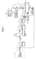
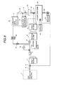
- FIG. 7 and FIG. 8 are diagram showing the construction of this embodiment of a system for collecting and refining SF 6 gas.
- the system for collecting and refining SF 6 gas of this embodiment is constructed similar to the embodiment shown in FIG. 1. However, in the system for collecting and refining SF 6 gas of this embodiment, a fourth filter 30 is arranged between the third filter 9 and the collecting tank 10. In the fourth filter 30, a porous hollow thread film for selectively separating air is installed.
- a produced amount that is, a concentration of gas component composition produced in the deteriorated SF 6 gas in which SF 6 gas is deteriorated is seldom deviated largely from the values shown in Table 3.
- air enters into the system by in-leakage from the outside of the system, and the concentration of air possibly becomes 100 times or 1000 times of the concentration shown in Table 1 if even one of fastened positions is loosed.
- the inside of the system other than the gas insulated machine is brought to a considerable vacuum condition in order to evacuation-collect SF 6 gas as much as possible. In this condition, potential of air to leak into the system from outside the system is increased.
- air containing N 2 , O 2 can be adsorbed and removed to a certain degree by an adsorbent of active carbon group, but the amount is as small as approximately 1 % of the amount of the adsorbent. Therefore, the air soon breaks through the absorbent.
- the air may be discharged out of the system from the collecting tank 10 as a non-condensable gas. However, this case is not preferable because the SF 6 gas is also released outside the system together with the air. Therefore, it is necessary to selectively separate and remove only the air among the collected gases.
- This embodiment realizes the selective separation and removal of the air using a porous hollow thread film having selective property.
- the acidic gases and the carbon dioxide gas accompanied by the SF 6 gas are removed by the first filter 4, and the by-product gases are removed in the second filter 8. Further, the moisture is removed in the third filter 9.
- the air containing N 2 , O 2 is separated and removed by the porous hollow thread film filter in the fourth filter 30.
- the gas is pumped into the fourth filter 30 by the compressor 6.
- the film filter can cope with a large amount of air in-leaking because the film filter cannot be broken through by the air, and the film filter does not produce the secondary waste such as a disposed filling agent (disposed adsorbent).
- the fourth filter 30 is arranged between the collecting tank 10 and the inlet of the compressor 6, and a branch portion is arranged in a position of the upstream side of the compressor 6 and the downstream side of the vacuum pump 7, and the forth filter 30 is connected to the branch portion through a pressure reducing valve 31.
- the fourth filter 30 is further connected to the analysis equipment 14, and the porous hollow thread film is arranged for selectively separate air is installed in the fourth filter 30.
- the gas passes through the fourth filter 30 only once.
- a predetermined amount of the gas is re-circulated by supplying the gas from the gas phase portion of the collecting tank 10 where the concentration of air of a non-condensable gas is high to the inlet portion of the compressor 6 through the pressure reducing valve 31.
- the re-circulation flow rate is controlled by the pressure reducing valve 31. Since the collecting tank 10 in this case is in a positive pressure, no driving source for applying a positive pressure to the film is necessary.
- the efficiency of separating and removing the air can be substantially improved by re-circulating the gas in the gas phase portion where the concentration of air of a non-condensable gas is high in the collecting tank 10 and processing the gas using the fourth filter 30. Further, since this filter is of a film separating type, the secondary waste is not produced.
- the deteriorated SF 6 gas is efficiently collected from the gas insulated machine, and impurities accompanying with the SF 6 gas are separated and removed, and the composition of the collected SF 6 gas can be measured and confirmed. Therefore, collecting, refining and reusing of the deteriorated SF 6 gas can be speedy performed at the installation site of the machine. Thereby, it is possible to prevent the SF 6 gas harmful to the global environment from releasing to atmosphere, and to make effective use of resources. Further, by using the dry type filter for the refining process, it is possible to make the system small in size, to keep the portability of the system and to reduce the amount of the secondary waste.
Landscapes
- Chemical & Material Sciences (AREA)
- Chemical Kinetics & Catalysis (AREA)
- Engineering & Computer Science (AREA)
- Organic Chemistry (AREA)
- Inorganic Chemistry (AREA)
- General Chemical & Material Sciences (AREA)
- Health & Medical Sciences (AREA)
- Oil, Petroleum & Natural Gas (AREA)
- Analytical Chemistry (AREA)
- Power Engineering (AREA)
- Environmental & Geological Engineering (AREA)
- Biomedical Technology (AREA)
- Gas-Insulated Switchgears (AREA)
- Treating Waste Gases (AREA)
- Pipeline Systems (AREA)
Description

| Moisture | lower than 15 wt ppm |
| Air | lower than 500 wt ppm |
| Hydrolytic fluoride (HF) | lower than 1.0 wt ppm |
| Example of a result of analyzing components of a deteriorated SF6 gas | |||
| No. | Item | Contents | Concentration (ppm) |
| 1 | Solids | Fluorides, Sulfides and | |
| 2 | Acidic gases | SF4, SF2, S2F2, SOF2, SO2F2, HF and the like | 5000 |
| 3 | Carbon dioxide | CO2 | 1500 |
| 4 | PFC | CF4, C2F6, C2F4 and the like | 1000 |
| 5 | Air | O2, N2 | 600 |
| 6 | Moisture | H2O | 20 |
| Examples of applicable measurement apparatus | |||
| No. | Item | Measurement Apparatus | Measurable Lower Limit (ppm) |
| 1 | Acidic gases | Acidic gas detector, Gas chromatograph | approximately 0.5 |
| 2 | Carbon dioxide | Gas chromatograph | approximately 0.5 |
| 3 | PFC | Gas chromatograph | approximately 10 |
| 4 | Air | Oxygen meter | approximately 10 |
| 5 | Humidity | Dew point meter, Humidity meter | approximately 5 |
Claims (7)
- A system for collecting and refining SF6 gas comprisingwherein said first filter (4) is filled with a dry adsorbent.a first filter (4) connected to a gas insulated machine (1),a constant flow rate supplier (5) connected to the down-stream side of said first filter (4),
a compressor (6) and a vacuum pump (7a) connected in parallel to the downstream side of said constant flow rate supplier (5),a collecting tank (10) connected to the downstream side of said compressor (6), anda cooler (20) for cooling said collecting tank (10), - The system of claim 1, comprising a constant flow rate valve arranged at the inlet side of said compressor (6).
- The system of claim 1, wherein said first filter (4) is filled with a calcium group alkali.
- The system of claim 1, comprisingat least a second filter (8) arranged between said compressor (6) and said collecting tank (10), andan analysis equipment (14) including a gaschromatograph at the downstream side of said second filter (8).
- The system of claim 1, comprising a returning pipe for returning SF6 gas from said collecting tank (10) to said gas insulated machine (1).
- A method of collecting and refining SF6 gas, comprising the steps of:removing impurities from SF6 gas from a gas insulated machine (1) by averaging the SF6 gas flow rate and letting the SF6 gas flow through a first filter (4) filled with a dry adsorbent,adsorbing and removing by-product gases by a second filter (8) filled with a dry adsorbent, andcollecting the SF6 gas separated by said second filter (8) by cooling and liquefying the SF6 gas.
- The method of claim 6, comprising the further step ofconfirming compositions of said collected SF6 gas by analysing compositions on analysis items of moisture concentration, acidic gas concentration, carbon dioxide concentration, any one of oxygen and nitrogen concentration and PFC concentration, andrepeating said process of confirming said compositions and returning said collected SF6 gas to said first filter (4) until said compositions become target values.
Applications Claiming Priority (3)
| Application Number | Priority Date | Filing Date | Title |
|---|---|---|---|
| JP16371597 | 1997-06-20 | ||
| JP16371597A JP3356965B2 (en) | 1997-06-20 | 1997-06-20 | SF6 gas recovery / purification processing apparatus and method |
| JP163715/97 | 1997-06-20 |
Publications (2)
| Publication Number | Publication Date |
|---|---|
| EP0885841A1 EP0885841A1 (en) | 1998-12-23 |
| EP0885841B1 true EP0885841B1 (en) | 2001-03-21 |
Family
ID=15779274
Family Applications (1)
| Application Number | Title | Priority Date | Filing Date |
|---|---|---|---|
| EP98111045A Revoked EP0885841B1 (en) | 1997-06-20 | 1998-06-16 | System and method for collecting and refining SF6 gas |
Country Status (6)
| Country | Link |
|---|---|
| US (1) | US6004377A (en) |
| EP (1) | EP0885841B1 (en) |
| JP (1) | JP3356965B2 (en) |
| KR (1) | KR100308404B1 (en) |
| DE (1) | DE69800609T2 (en) |
| TW (1) | TW448069B (en) |
Cited By (2)
| Publication number | Priority date | Publication date | Assignee | Title |
|---|---|---|---|---|
| EP3834917A1 (en) * | 2019-12-13 | 2021-06-16 | WIKA Alexander Wiegand SE & Co. KG | Service system for gas areas |
| DE102022120939A1 (en) | 2022-08-18 | 2024-02-29 | Dilo Armaturen Und Anlagen Gmbh | Drying system for insulating gases and process for drying gases |
Families Citing this family (61)
| Publication number | Priority date | Publication date | Assignee | Title |
|---|---|---|---|---|
| DE19923155A1 (en) * | 1999-05-20 | 2000-11-23 | Solvay Fluor & Derivate | Process for removing sulfur hexafluoride/nitrogen mixtures from gas-isolated lines comprises contacting the gas mixture with a membrane |
| JP4357046B2 (en) * | 1999-10-01 | 2009-11-04 | 株式会社東芝 | Gas recovery device |
| JP2002035528A (en) * | 2000-07-26 | 2002-02-05 | Japan Atom Energy Res Inst | Gas separation equipment |
| JP2002147948A (en) * | 2000-11-10 | 2002-05-22 | Japan Organo Co Ltd | Gas separation device and gas separation method |
| GB0101769D0 (en) | 2001-01-24 | 2001-03-07 | Ineos Fluor Ltd | Decomposition of fluorine compounds |
| JP2003103134A (en) * | 2001-09-28 | 2003-04-08 | Toshiba Corp | SF6 gas trapping apparatus and method |
| AU2005250504B2 (en) * | 2004-06-02 | 2010-06-03 | Hitachi Energy Ltd | Apparatus and method for capturing and containing sulphur hexafluoride gas leakage |
| US8042580B2 (en) * | 2004-06-02 | 2011-10-25 | Golden Triangle Enterprises Pty Ltd | Apparatus and method for capturing and containing sulphur hexafluoride gas leakage |
| JP4212106B2 (en) * | 2005-04-19 | 2009-01-21 | オルガノ株式会社 | Gas separation device and gas separation method |
| KR20080029497A (en) * | 2006-09-29 | 2008-04-03 | 삼성전자주식회사 | Plasma processing equipment and substrate processing method using the same |
| KR100764109B1 (en) * | 2007-03-16 | 2007-10-05 | 우성진공기술(주) | Sulfur hexafluoride gas liquefaction recovery system |
| JP2009018269A (en) * | 2007-07-12 | 2009-01-29 | Japan Organo Co Ltd | Gas separation device and gas separation method |
| JP2009099501A (en) * | 2007-10-19 | 2009-05-07 | Toshiba Corp | Gas recovery apparatus and method |
| JP5541893B2 (en) * | 2009-09-15 | 2014-07-09 | 中部システム工業株式会社 | Gas extraction device and gas analyzer using the same |
| FR2951860B1 (en) * | 2009-10-27 | 2011-12-23 | Areva T & D Sas | DEVICE AND METHOD FOR THE RECOVERY OF INSULATION GAS CONTAINED IN A HIGH VOLTAGE OR MEDIUM VOLTAGE CIRCUIT BREAKER |
| JP5517128B2 (en) * | 2010-06-30 | 2014-06-11 | 公益財団法人若狭湾エネルギー研究センター | SF6 gas recovery apparatus and SF6 gas recovery method |
| CN101955164A (en) * | 2010-10-18 | 2011-01-26 | 天津市泰亨气体有限公司 | Method for producing and purifying sulfur hexafluoride |
| JP4769333B1 (en) * | 2010-11-02 | 2011-09-07 | 大陽日酸東関東株式会社 | Purity estimation device for recovered liquefied SF6 gas and purity estimation method thereof |
| KR101086311B1 (en) * | 2011-07-15 | 2011-11-23 | 주식회사 경기기술공사 | Gas filter device for sulfur hexafluoride gas insulated switchgear |
| KR101410712B1 (en) * | 2012-02-23 | 2014-06-24 | (주)파인텍 | The separation and recycling system for a perfluoro compounds |
| KR101410914B1 (en) * | 2012-02-23 | 2014-06-24 | (주)파인텍 | The separation and recycling system for a perfluoro compounds |
| FR2992871B1 (en) * | 2012-07-05 | 2015-02-20 | Dehon S A | PURIFICATION DEVICE AND METHOD FOR REGENERATING SF6 |
| EP2904617B1 (en) | 2012-10-05 | 2016-11-30 | ABB Schweiz AG | Apparatus containing a dielectric insulation gas comprising an organofluorine compound |
| CN103836340A (en) * | 2012-11-20 | 2014-06-04 | 贵阳铝镁设计研究院有限公司 | Method for guaranteeing safe operation of multiple gas discharging and conveying machines and connecting structure |
| KR101315995B1 (en) * | 2013-05-06 | 2013-10-10 | 샤론일렉콤 주식회사 | Apparatus for managing insulating gas of ground equipment in live wire and method thereof |
| WO2014187940A1 (en) * | 2013-05-23 | 2014-11-27 | Abb Technology Ag | Electrical apparatus comprising a contamination-reducing component |
| KR101371667B1 (en) * | 2013-12-27 | 2014-03-07 | 대흥전력기술 주식회사 | Method for checking and changing insulating gas of load break switch on live wire state |
| MX2016014972A (en) | 2014-05-20 | 2017-05-12 | Abb Schweiz Ag | Electrical apparatus for the generation, transmission, distribution and/or usage of electrical energy and method for recovering a substance from an insulation medium of such an apparatus. |
| US10375901B2 (en) | 2014-12-09 | 2019-08-13 | Mtd Products Inc | Blower/vacuum |
| DE102015206744A1 (en) * | 2015-04-15 | 2016-11-03 | Rwe Deutschland Ag | Method for drying a gas space and arrangement comprising a protective gas-filled gas space |
| WO2016204630A1 (en) * | 2015-06-18 | 2016-12-22 | Pringle Beleski And Associates Limited | System and method for gas management |
| EP3118955A1 (en) * | 2015-07-17 | 2017-01-18 | ABB Schweiz AG | Gas insulated switchgear with the use of eco efficient insulating gases, and method of producing the same |
| DE102015213597A1 (en) * | 2015-07-20 | 2017-01-26 | Siemens Aktiengesellschaft | High or medium voltage arrangement with insulating space and absorbent |
| CN105202360A (en) * | 2015-09-16 | 2015-12-30 | 四川菲博斯科技有限责任公司 | SF6 air inflation equipment of electrical equipment |
| CN105202359A (en) * | 2015-09-16 | 2015-12-30 | 四川菲博斯科技有限责任公司 | SF6 air inflation equipment of electrical equipment |
| CN105202358A (en) * | 2015-09-16 | 2015-12-30 | 四川菲博斯科技有限责任公司 | SF6 air inflation device of electrical equipment |
| DE102016215598A1 (en) * | 2016-08-19 | 2018-02-22 | Siemens Aktiengesellschaft | Electric power transmission device and life cycle management |
| CN106377980A (en) * | 2016-10-08 | 2017-02-08 | 国家电网公司 | GIS (Gas Insulated Switchgear) equipment SF6 humidity overproof no-power-outage processing method and device thereof |
| CN107965664B (en) * | 2017-11-22 | 2019-07-30 | 中国西电电气股份有限公司 | A kind of pair of transformer carries out the device and method of automatic inflating device deflation |
| CN108417434B (en) * | 2018-05-15 | 2019-08-02 | 梁旭泽 | A kind of breaker auxiliary device |
| CN109004571B (en) * | 2018-07-26 | 2020-08-25 | 广西金德泰电气有限公司 | Gas-insulated closed compact metal-enclosed switch |
| KR102094740B1 (en) * | 2018-08-27 | 2020-04-23 | 한국전력공사 | A sf6 refinement system and method including hybrid reactors utilizing gas hydrate formation |
| CN109442225B (en) * | 2018-12-18 | 2022-02-25 | 河南省日立信股份有限公司 | Insulation gas online monitoring system and method for preventing and detecting pipeline leakage |
| US11052347B2 (en) * | 2018-12-21 | 2021-07-06 | Entegris, Inc. | Bulk process gas purification systems |
| CN111014861B (en) * | 2019-12-31 | 2022-02-08 | 牧野机床(中国)有限公司 | Working method of filtering device of linear cutting machine |
| CN111547685B (en) * | 2020-04-10 | 2022-01-25 | 国网河北省电力有限公司电力科学研究院 | Low-concentration SF6 gas recovery processing device and method in closed space |
| CN111760425A (en) * | 2020-07-10 | 2020-10-13 | 国网湖南省电力有限公司 | A kind of online processing device and method for GIS equipment SF6 humidity exceeding standard without power failure |
| CN112107959A (en) * | 2020-07-31 | 2020-12-22 | 国网安徽省电力有限公司电力科学研究院 | Emergency recovery device and method for leaked gas of electrical equipment |
| CN111952881B (en) * | 2020-08-24 | 2022-05-03 | 海南电网有限责任公司琼中供电局 | Safety early warning device |
| CN112705003A (en) * | 2020-12-25 | 2021-04-27 | 格林美(江苏)钴业股份有限公司 | Method for treating VOC waste gas in extraction system by adopting activated carbon |
| CN113041729A (en) * | 2021-03-29 | 2021-06-29 | 广东电网有限责任公司东莞供电局 | Two-channel SF6 gas purification device |
| KR102286094B1 (en) | 2021-04-13 | 2021-08-06 | 유한회사 대영글로벌 | GIS 6 fluoride sulfur gas input and output inventory storage system |
| CN113193505B (en) * | 2021-04-27 | 2022-07-15 | 国网新疆电力有限公司昌吉供电公司 | A fault warning device for power distribution site |
| CN113775921A (en) * | 2021-09-06 | 2021-12-10 | 国网江苏省电力有限公司电力科学研究院 | On-site positive pressure recovery device and method for sulfur hexafluoride gas |
| KR102484761B1 (en) | 2021-09-10 | 2023-01-05 | 김용배 | A device that can automatically check and record vacuum in substation facilities |
| CN113852030A (en) * | 2021-11-09 | 2021-12-28 | 广东电网有限责任公司电力科学研究院 | GIL insulating gas self-circulation filter device |
| CN114440133B (en) * | 2021-12-17 | 2024-10-15 | 河南平高电气股份有限公司 | Monitoring module and flow meter correction method for SF6 gas filling and degassing recovery device |
| CN115055027A (en) * | 2022-07-08 | 2022-09-16 | 国网浙江省电力有限公司桐乡市供电公司 | Insulating medium purifies and air supplement unit in insulating gas switch cabinet air chamber of environmental protection |
| CN115560237A (en) * | 2022-10-19 | 2023-01-03 | 国网湖北省电力有限公司 | A kind of SF6 recovery storage transfer device and its use method |
| KR102843224B1 (en) * | 2022-11-25 | 2025-08-06 | (주)오운알투텍 | Recovery apparatus for for sulfur hexafluoride waste gas and Recovery Method using the same |
| JP7284551B1 (en) * | 2023-03-14 | 2023-05-31 | 日本協同エネルギー株式会社 | Sulfur hexafluoride gas storage structure and storage method |
Family Cites Families (20)
| Publication number | Priority date | Publication date | Assignee | Title |
|---|---|---|---|---|
| US3102013A (en) * | 1960-08-02 | 1963-08-27 | Exxon Research Engineering Co | Heatless fractionation utilizing zones in series and parallel |
| US3619130A (en) * | 1968-08-27 | 1971-11-09 | Frank J Ventriglio | Method of removing carbon dioxide from gaseous mixtures |
| US3675392A (en) * | 1970-01-30 | 1972-07-11 | Ite Imperial Corp | Adsorption-desorption method for purifying sf{11 |
| DE2459998A1 (en) * | 1974-12-16 | 1976-07-01 | Siemens Ag | Insulated sulphur hexafluoride HV switchgear - has insulating gas cleaning device using compression and partial condensation of contaminants |
| US4369048A (en) * | 1980-01-28 | 1983-01-18 | Dallas T. Pence | Method for treating gaseous effluents emitted from a nuclear reactor |
| US4433981A (en) * | 1981-02-18 | 1984-02-28 | Shell Oil Company | CO2 Removal from gaseous streams |
| GB2103195B (en) * | 1981-07-20 | 1985-04-11 | Gni Energet I Im Gm Krzhizhano | Process for fine purification of sulphur hexafluoride |
| US4449991A (en) * | 1982-12-20 | 1984-05-22 | Exxon Research And Engineering Co. | Removal of sulfur from process streams |
| EP0173640A3 (en) * | 1984-07-30 | 1986-12-30 | Mitsubishi Jukogyo Kabushiki Kaisha | Method for treating exhaust gas |
| US5411707A (en) * | 1992-06-25 | 1995-05-02 | The United States Of American As Represented By The Administrator Of The Environmental Protection Agency | Vacuum extractor incorporating a condenser column |
| NL9201179A (en) * | 1992-07-02 | 1994-02-01 | Tno | PROCESS FOR THE REGENERATIVE REMOVAL OF CARBON DIOXIDE FROM GAS FLOWS. |
| CN1030375C (en) * | 1992-12-19 | 1995-11-29 | 中国科学院大连化学物理研究所 | Modified molecular sieve adsorbent for sulfur hexafluoride gas purification and its preparation |
| CA2133302A1 (en) * | 1993-10-06 | 1995-04-07 | Ravi Kumar | Integrated process for purifying and liquefying a feed gas mixture with respect to its less strongly adsorbed component of lower volatility |
| JPH09856A (en) * | 1995-06-12 | 1997-01-07 | Toshiba Corp | Decomposition gas treatment equipment for SF6 gas insulated electrical equipment |
| DE19528290C1 (en) * | 1995-08-02 | 1997-01-23 | Ges Foerderung Spektrochemie | Procedure for monitoring the quality of the filling gas sulfur hexafluoride in gas-filled systems |
| FR2743082B1 (en) * | 1995-12-27 | 1999-02-19 | Inst Francais Du Petrole | GLOBAL PROCESSING OF NATURAL GAS ON A STORAGE SITE |
| US5833738A (en) * | 1996-03-01 | 1998-11-10 | D.D.I. Ltd. | Specialty gas purification system |
| US5759237A (en) * | 1996-06-14 | 1998-06-02 | L'air Liquide Societe Anonyme Pour L'etude Et, L'exploitation Des Procedes Georges Claude | Process and system for selective abatement of reactive gases and recovery of perfluorocompound gases |
| US5762686A (en) * | 1996-09-04 | 1998-06-09 | Special Gas System, Inc. | Process for determining amount of argon contamination in oxygen and related apparatus therefor |
| US5720797A (en) * | 1996-12-18 | 1998-02-24 | Alliedsignal Inc. | Process for recovering sulfur hexafluoride |
-
1997
- 1997-06-20 JP JP16371597A patent/JP3356965B2/en not_active Expired - Fee Related
-
1998
- 1998-06-16 EP EP98111045A patent/EP0885841B1/en not_active Revoked
- 1998-06-16 US US09/097,707 patent/US6004377A/en not_active Expired - Fee Related
- 1998-06-16 DE DE69800609T patent/DE69800609T2/en not_active Expired - Fee Related
- 1998-06-17 TW TW087109699A patent/TW448069B/en not_active IP Right Cessation
- 1998-06-19 KR KR1019980023057A patent/KR100308404B1/en not_active Expired - Fee Related
Cited By (2)
| Publication number | Priority date | Publication date | Assignee | Title |
|---|---|---|---|---|
| EP3834917A1 (en) * | 2019-12-13 | 2021-06-16 | WIKA Alexander Wiegand SE & Co. KG | Service system for gas areas |
| DE102022120939A1 (en) | 2022-08-18 | 2024-02-29 | Dilo Armaturen Und Anlagen Gmbh | Drying system for insulating gases and process for drying gases |
Also Published As
| Publication number | Publication date |
|---|---|
| TW448069B (en) | 2001-08-01 |
| EP0885841A1 (en) | 1998-12-23 |
| KR19990007129A (en) | 1999-01-25 |
| JPH119951A (en) | 1999-01-19 |
| JP3356965B2 (en) | 2002-12-16 |
| DE69800609T2 (en) | 2001-11-15 |
| US6004377A (en) | 1999-12-21 |
| KR100308404B1 (en) | 2002-02-19 |
| DE69800609D1 (en) | 2001-04-26 |
Similar Documents
| Publication | Publication Date | Title |
|---|---|---|
| US6004377A (en) | System for collecting and refining SF6 gas and method therefor | |
| KR100764109B1 (en) | Sulfur hexafluoride gas liquefaction recovery system | |
| EP2463012B1 (en) | Method and equipment for selectively collecting process effluent gases | |
| KR100427676B1 (en) | Process or recovery of gaseous hydrocarbons contained in waste gas | |
| EP1091182B1 (en) | Gas reclaiming equipment | |
| WO1991013679A1 (en) | Bulk gas sorption composition and apparatus | |
| US20060248921A1 (en) | Landfill gas purification and liquefaction process | |
| JP3237514B2 (en) | Sulfur hexafluoride gas recovery and regeneration device and mobile recovery and regeneration device | |
| RU2366873C2 (en) | System and method for sulphur hexafluoride extraction in gaseous phase | |
| JP2003103134A (en) | SF6 gas trapping apparatus and method | |
| KR20010114209A (en) | Method for treating dilute gaseous hydrogen carbide contained in waste gas and device for performing the method | |
| JP2925522B2 (en) | Method for recovering hydrocarbons in liquid form from waste gas containing gaseous hydrocarbons | |
| KR200437124Y1 (en) | SF6 gas recovery and reuse feeder with SF6 gas purity meter | |
| CN217479385U (en) | Oil gas recovery system | |
| JP2000102123A (en) | Condensable gas recovery device | |
| JP2003044146A (en) | Specific gas filling concentration controller | |
| JPH10285730A (en) | Gas supply / discharge device | |
| JP2005090988A (en) | Drying method and drying equipment system for tritium-containing heavy water handling equipment | |
| JP2001314726A (en) | Gas separation recovery filling equipment | |
| JP2002037611A (en) | Gas recovery apparatus and method | |
| JP3226849B2 (en) | Method and apparatus for recovering foam gas from foam insulation | |
| JP2001280593A (en) | Gas separation and recovery equipment | |
| Neumann et al. | High capacity Helium purifier for 14 g/s at 200 bar | |
| CN115999341A (en) | SF in limited space 6 Deep gas decomposition and adsorption device and method | |
| JP2000035199A (en) | Welding gas recovery device |
Legal Events
| Date | Code | Title | Description |
|---|---|---|---|
| PUAI | Public reference made under article 153(3) epc to a published international application that has entered the european phase |
Free format text: ORIGINAL CODE: 0009012 |
|
| AK | Designated contracting states |
Kind code of ref document: A1 Designated state(s): DE GB |
|
| AX | Request for extension of the european patent |
Free format text: AL;LT;LV;MK;RO;SI |
|
| 17P | Request for examination filed |
Effective date: 19990323 |
|
| AKX | Designation fees paid |
Free format text: DE GB |
|
| GRAG | Despatch of communication of intention to grant |
Free format text: ORIGINAL CODE: EPIDOS AGRA |
|
| 17Q | First examination report despatched |
Effective date: 20000427 |
|
| GRAG | Despatch of communication of intention to grant |
Free format text: ORIGINAL CODE: EPIDOS AGRA |
|
| GRAG | Despatch of communication of intention to grant |
Free format text: ORIGINAL CODE: EPIDOS AGRA |
|
| GRAH | Despatch of communication of intention to grant a patent |
Free format text: ORIGINAL CODE: EPIDOS IGRA |
|
| GRAH | Despatch of communication of intention to grant a patent |
Free format text: ORIGINAL CODE: EPIDOS IGRA |
|
| GRAA | (expected) grant |
Free format text: ORIGINAL CODE: 0009210 |
|
| AK | Designated contracting states |
Kind code of ref document: B1 Designated state(s): DE GB |
|
| REF | Corresponds to: |
Ref document number: 69800609 Country of ref document: DE Date of ref document: 20010426 |
|
| EN | Fr: translation not filed | ||
| PGFP | Annual fee paid to national office [announced via postgrant information from national office to epo] |
Ref country code: DE Payment date: 20010828 Year of fee payment: 4 |
|
| PLBQ | Unpublished change to opponent data |
Free format text: ORIGINAL CODE: EPIDOS OPPO |
|
| PLBI | Opposition filed |
Free format text: ORIGINAL CODE: 0009260 |
|
| REG | Reference to a national code |
Ref country code: GB Ref legal event code: IF02 |
|
| PLBF | Reply of patent proprietor to notice(s) of opposition |
Free format text: ORIGINAL CODE: EPIDOS OBSO |
|
| 26 | Opposition filed |
Opponent name: DILO ARMATUREN- UND ANLAGEN GMBH Effective date: 20011218 |
|
| PG25 | Lapsed in a contracting state [announced via postgrant information from national office to epo] |
Ref country code: GB Free format text: LAPSE BECAUSE OF NON-PAYMENT OF DUE FEES Effective date: 20020616 |
|
| PLBF | Reply of patent proprietor to notice(s) of opposition |
Free format text: ORIGINAL CODE: EPIDOS OBSO |
|
| PG25 | Lapsed in a contracting state [announced via postgrant information from national office to epo] |
Ref country code: DE Free format text: LAPSE BECAUSE OF NON-PAYMENT OF DUE FEES Effective date: 20030101 |
|
| GBPC | Gb: european patent ceased through non-payment of renewal fee |
Effective date: 20020616 |
|
| RDAH | Patent revoked |
Free format text: ORIGINAL CODE: EPIDOS REVO |
|
| RDAG | Patent revoked |
Free format text: ORIGINAL CODE: 0009271 |
|
| STAA | Information on the status of an ep patent application or granted ep patent |
Free format text: STATUS: PATENT REVOKED |
|
| 27W | Patent revoked |
Effective date: 20030801 |