JP4212106B2 - Gas separation device and gas separation method - Google Patents
Gas separation device and gas separation method Download PDFInfo
- Publication number
- JP4212106B2 JP4212106B2 JP2005120668A JP2005120668A JP4212106B2 JP 4212106 B2 JP4212106 B2 JP 4212106B2 JP 2005120668 A JP2005120668 A JP 2005120668A JP 2005120668 A JP2005120668 A JP 2005120668A JP 4212106 B2 JP4212106 B2 JP 4212106B2
- Authority
- JP
- Japan
- Prior art keywords
- gas
- separation
- column
- pfc
- concentration
- Prior art date
- Legal status (The legal status is an assumption and is not a legal conclusion. Google has not performed a legal analysis and makes no representation as to the accuracy of the status listed.)
- Expired - Fee Related
Links
Images


Classifications
-
- B—PERFORMING OPERATIONS; TRANSPORTING
- B01—PHYSICAL OR CHEMICAL PROCESSES OR APPARATUS IN GENERAL
- B01D—SEPARATION
- B01D53/00—Separation of gases or vapours; Recovering vapours of volatile solvents from gases; Chemical or biological purification of waste gases, e.g. engine exhaust gases, smoke, fumes, flue gases, aerosols
- B01D53/34—Chemical or biological purification of waste gases
- B01D53/46—Removing components of defined structure
- B01D53/68—Halogens or halogen compounds
-
- B—PERFORMING OPERATIONS; TRANSPORTING
- B01—PHYSICAL OR CHEMICAL PROCESSES OR APPARATUS IN GENERAL
- B01D—SEPARATION
- B01D53/00—Separation of gases or vapours; Recovering vapours of volatile solvents from gases; Chemical or biological purification of waste gases, e.g. engine exhaust gases, smoke, fumes, flue gases, aerosols
- B01D53/02—Separation of gases or vapours; Recovering vapours of volatile solvents from gases; Chemical or biological purification of waste gases, e.g. engine exhaust gases, smoke, fumes, flue gases, aerosols by adsorption, e.g. preparative gas chromatography
- B01D53/04—Separation of gases or vapours; Recovering vapours of volatile solvents from gases; Chemical or biological purification of waste gases, e.g. engine exhaust gases, smoke, fumes, flue gases, aerosols by adsorption, e.g. preparative gas chromatography with stationary adsorbents
- B01D53/047—Pressure swing adsorption
-
- B—PERFORMING OPERATIONS; TRANSPORTING
- B01—PHYSICAL OR CHEMICAL PROCESSES OR APPARATUS IN GENERAL
- B01D—SEPARATION
- B01D53/00—Separation of gases or vapours; Recovering vapours of volatile solvents from gases; Chemical or biological purification of waste gases, e.g. engine exhaust gases, smoke, fumes, flue gases, aerosols
- B01D53/02—Separation of gases or vapours; Recovering vapours of volatile solvents from gases; Chemical or biological purification of waste gases, e.g. engine exhaust gases, smoke, fumes, flue gases, aerosols by adsorption, e.g. preparative gas chromatography
- B01D53/04—Separation of gases or vapours; Recovering vapours of volatile solvents from gases; Chemical or biological purification of waste gases, e.g. engine exhaust gases, smoke, fumes, flue gases, aerosols by adsorption, e.g. preparative gas chromatography with stationary adsorbents
-
- B—PERFORMING OPERATIONS; TRANSPORTING
- B01—PHYSICAL OR CHEMICAL PROCESSES OR APPARATUS IN GENERAL
- B01D—SEPARATION
- B01D53/00—Separation of gases or vapours; Recovering vapours of volatile solvents from gases; Chemical or biological purification of waste gases, e.g. engine exhaust gases, smoke, fumes, flue gases, aerosols
- B01D53/34—Chemical or biological purification of waste gases
- B01D53/46—Removing components of defined structure
- B01D53/68—Halogens or halogen compounds
- B01D53/70—Organic halogen compounds
-
- B—PERFORMING OPERATIONS; TRANSPORTING
- B01—PHYSICAL OR CHEMICAL PROCESSES OR APPARATUS IN GENERAL
- B01D—SEPARATION
- B01D53/00—Separation of gases or vapours; Recovering vapours of volatile solvents from gases; Chemical or biological purification of waste gases, e.g. engine exhaust gases, smoke, fumes, flue gases, aerosols
- B01D53/34—Chemical or biological purification of waste gases
- B01D53/74—General processes for purification of waste gases; Apparatus or devices specially adapted therefor
- B01D53/75—Multi-step processes
-
- C—CHEMISTRY; METALLURGY
- C23—COATING METALLIC MATERIAL; COATING MATERIAL WITH METALLIC MATERIAL; CHEMICAL SURFACE TREATMENT; DIFFUSION TREATMENT OF METALLIC MATERIAL; COATING BY VACUUM EVAPORATION, BY SPUTTERING, BY ION IMPLANTATION OR BY CHEMICAL VAPOUR DEPOSITION, IN GENERAL; INHIBITING CORROSION OF METALLIC MATERIAL OR INCRUSTATION IN GENERAL
- C23C—COATING METALLIC MATERIAL; COATING MATERIAL WITH METALLIC MATERIAL; SURFACE TREATMENT OF METALLIC MATERIAL BY DIFFUSION INTO THE SURFACE, BY CHEMICAL CONVERSION OR SUBSTITUTION; COATING BY VACUUM EVAPORATION, BY SPUTTERING, BY ION IMPLANTATION OR BY CHEMICAL VAPOUR DEPOSITION, IN GENERAL
- C23C16/00—Chemical coating by decomposition of gaseous compounds, without leaving reaction products of surface material in the coating, i.e. chemical vapour deposition [CVD] processes
- C23C16/44—Chemical coating by decomposition of gaseous compounds, without leaving reaction products of surface material in the coating, i.e. chemical vapour deposition [CVD] processes characterised by the method of coating
- C23C16/4412—Details relating to the exhausts, e.g. pumps, filters, scrubbers, particle traps
-
- B—PERFORMING OPERATIONS; TRANSPORTING
- B01—PHYSICAL OR CHEMICAL PROCESSES OR APPARATUS IN GENERAL
- B01D—SEPARATION
- B01D2253/00—Adsorbents used in seperation treatment of gases and vapours
- B01D2253/10—Inorganic adsorbents
- B01D2253/102—Carbon
-
- B—PERFORMING OPERATIONS; TRANSPORTING
- B01—PHYSICAL OR CHEMICAL PROCESSES OR APPARATUS IN GENERAL
- B01D—SEPARATION
- B01D2253/00—Adsorbents used in seperation treatment of gases and vapours
- B01D2253/10—Inorganic adsorbents
- B01D2253/106—Silica or silicates
- B01D2253/108—Zeolites
-
- B—PERFORMING OPERATIONS; TRANSPORTING
- B01—PHYSICAL OR CHEMICAL PROCESSES OR APPARATUS IN GENERAL
- B01D—SEPARATION
- B01D2256/00—Main component in the product gas stream after treatment
- B01D2256/10—Nitrogen
-
- B—PERFORMING OPERATIONS; TRANSPORTING
- B01—PHYSICAL OR CHEMICAL PROCESSES OR APPARATUS IN GENERAL
- B01D—SEPARATION
- B01D2257/00—Components to be removed
- B01D2257/20—Halogens or halogen compounds
- B01D2257/204—Inorganic halogen compounds
-
- B—PERFORMING OPERATIONS; TRANSPORTING
- B01—PHYSICAL OR CHEMICAL PROCESSES OR APPARATUS IN GENERAL
- B01D—SEPARATION
- B01D2257/00—Components to be removed
- B01D2257/20—Halogens or halogen compounds
- B01D2257/206—Organic halogen compounds
- B01D2257/2066—Fluorine
-
- B—PERFORMING OPERATIONS; TRANSPORTING
- B01—PHYSICAL OR CHEMICAL PROCESSES OR APPARATUS IN GENERAL
- B01D—SEPARATION
- B01D2258/00—Sources of waste gases
- B01D2258/02—Other waste gases
- B01D2258/0216—Other waste gases from CVD treatment or semi-conductor manufacturing
-
- B—PERFORMING OPERATIONS; TRANSPORTING
- B01—PHYSICAL OR CHEMICAL PROCESSES OR APPARATUS IN GENERAL
- B01D—SEPARATION
- B01D2259/00—Type of treatment
- B01D2259/40—Further details for adsorption processes and devices
- B01D2259/40001—Methods relating to additional, e.g. intermediate, treatment of process gas
-
- B—PERFORMING OPERATIONS; TRANSPORTING
- B01—PHYSICAL OR CHEMICAL PROCESSES OR APPARATUS IN GENERAL
- B01D—SEPARATION
- B01D2259/00—Type of treatment
- B01D2259/40—Further details for adsorption processes and devices
- B01D2259/402—Further details for adsorption processes and devices using two beds
-
- B—PERFORMING OPERATIONS; TRANSPORTING
- B01—PHYSICAL OR CHEMICAL PROCESSES OR APPARATUS IN GENERAL
- B01D—SEPARATION
- B01D2259/00—Type of treatment
- B01D2259/40—Further details for adsorption processes and devices
- B01D2259/416—Further details for adsorption processes and devices involving cryogenic temperature treatment
-
- B—PERFORMING OPERATIONS; TRANSPORTING
- B01—PHYSICAL OR CHEMICAL PROCESSES OR APPARATUS IN GENERAL
- B01D—SEPARATION
- B01D53/00—Separation of gases or vapours; Recovering vapours of volatile solvents from gases; Chemical or biological purification of waste gases, e.g. engine exhaust gases, smoke, fumes, flue gases, aerosols
- B01D53/02—Separation of gases or vapours; Recovering vapours of volatile solvents from gases; Chemical or biological purification of waste gases, e.g. engine exhaust gases, smoke, fumes, flue gases, aerosols by adsorption, e.g. preparative gas chromatography
- B01D53/04—Separation of gases or vapours; Recovering vapours of volatile solvents from gases; Chemical or biological purification of waste gases, e.g. engine exhaust gases, smoke, fumes, flue gases, aerosols by adsorption, e.g. preparative gas chromatography with stationary adsorbents
- B01D53/0407—Constructional details of adsorbing systems
- B01D53/0423—Beds in columns
-
- Y—GENERAL TAGGING OF NEW TECHNOLOGICAL DEVELOPMENTS; GENERAL TAGGING OF CROSS-SECTIONAL TECHNOLOGIES SPANNING OVER SEVERAL SECTIONS OF THE IPC; TECHNICAL SUBJECTS COVERED BY FORMER USPC CROSS-REFERENCE ART COLLECTIONS [XRACs] AND DIGESTS
- Y02—TECHNOLOGIES OR APPLICATIONS FOR MITIGATION OR ADAPTATION AGAINST CLIMATE CHANGE
- Y02C—CAPTURE, STORAGE, SEQUESTRATION OR DISPOSAL OF GREENHOUSE GASES [GHG]
- Y02C20/00—Capture or disposal of greenhouse gases
- Y02C20/30—Capture or disposal of greenhouse gases of perfluorocarbons [PFC], hydrofluorocarbons [HFC] or sulfur hexafluoride [SF6]
Description
本発明は、少なくとも1成分の特定ガスを含有する被処理ガスから特定ガスを分離するガス分離装置及びガス分離方法に関する。 The present invention relates to a gas separation apparatus and a gas separation method for separating a specific gas from a gas to be processed containing at least one specific gas.
従来より、半導体製造工程、液晶製造工程等では、その工程に応じて、各種のガスが利用されている。例えば、ドライエッチング工程や薄膜形成工程などにおいて、CF4,NF3,C2F6,C3F8,SF6,CHF3,COF2などのフッ素を含む化合物であるPFC(perfluoro compound)ガスが反応性ガスとして使用され、これらを含む排ガスが生じる。 Conventionally, various gases are used in a semiconductor manufacturing process, a liquid crystal manufacturing process, and the like depending on the process. For example, PFC (perfluoro compound) gas which is a compound containing fluorine such as CF 4 , NF 3 , C 2 F 6 , C 3 F 8 , SF 6 , CHF 3 , COF 2 in a dry etching process or a thin film forming process. Is used as a reactive gas, and an exhaust gas containing these is generated.
これらPFCガスなどの排ガスは温暖化係数が高く、そのまま系外に排出することは好ましくないため、各種の処理方法で処理される。このような処理方法としては、燃焼式、触媒式、吸着式、プラズマ分解式などの除害処理によりPFCガスを分解、除害する方法がある。しかし、近年、環境保護や省エネルギの観点より、製造工程から排出されるPFCガスを回収再利用することが求められている。 Since the exhaust gas such as PFC gas has a high global warming potential and is not preferable to be discharged out of the system as it is, it is treated by various treatment methods. As such a treatment method, there is a method of decomposing and detoxifying the PFC gas by a detoxification treatment such as a combustion type, a catalyst type, an adsorption type, a plasma decomposition type or the like. However, in recent years, from the viewpoint of environmental protection and energy saving, it is required to recover and reuse PFC gas discharged from the manufacturing process.
また、一般に、PFCガスは製造工程からの排出時には、排出ラインや真空ポンプ等の保護のために多量の窒素等で希釈されて排出され、その濃度は条件に依存するが数%程度と低くなっている。そのため、この除害処理の場合、除害処理に不要な窒素等を除去して処理効率を上げるために、排ガスから窒素等を除去するPFC濃縮が有効である。 In general, PFC gas is discharged after being diluted with a large amount of nitrogen to protect the discharge line, vacuum pump, etc., and its concentration is as low as several percent, depending on the conditions. ing. Therefore, in the case of this detoxification treatment, PFC concentration for removing nitrogen and the like from exhaust gas is effective in order to remove nitrogen and the like unnecessary for the detoxification treatment and increase the treatment efficiency.
PFCガスを濃縮、回収する方法としては、各種充填材を使用したクロマトカラムを利用するクロマト分離により排ガスからPFCガスを分離して再利用する方法がある。例えば、特許文献1では、複数成分の特定ガスを含有する被処理ガスから特定ガスを分離するガス分離装置であって、活性炭が充填されたカラムを利用して被処理ガスをクロマト分離する分離手段を有するガス分離装置が提案されている。
As a method of concentrating and recovering PFC gas, there is a method of separating and reusing PFC gas from exhaust gas by chromatographic separation using a chromatographic column using various packing materials. For example, in
また、PFCガスを濃縮、回収する他の方法としては、膜によってPFCガスと窒素等とを分離する膜処理方法、PFCガスと窒素等との沸点の相違を利用して分離する深冷分離方法等が挙げられる。 Other methods for concentrating and recovering PFC gas include a membrane treatment method that separates PFC gas and nitrogen, etc. by a membrane, and a cryogenic separation method that separates using the difference in boiling point between PFC gas and nitrogen, etc. Etc.
例えば、非特許文献1には、ポリスルホン製高分子膜を3段使用した膜処理装置により0.05%のCF4を含有する窒素ガスからCF4を分離して回収することが記載されている。
For example, Non-Patent
しかしながら、特許文献1のようなクロマト分離の場合には、排ガス中の複数成分のPFCを分離することはできるが、クロマト分離のキャリアガスとして窒素等を使用するので、分離後のガスはキャリアガスの中にPFCを含有する形態となっている。そのため、PFCガスを回収して再利用を行うためには、分離後のガスから不純物となる窒素等を除去するPFC濃縮がさらに必要である。
However, in the case of chromatographic separation as in
また、膜処理方法では窒素とPFCとをある程度分離出来るが、その分離後のPFCの濃度は多段の膜処理でも90%程度しかなく、例えば、非特許文献1の方法では、0.05%のCF4を含有する窒素ガスから回収したCF4の濃度は91%(回収率97%)となっている。このため、膜処理方法により分離したPFCガスは、除害処理の前のPFC濃縮には適用できるが、PFCの濃度が新品のPFCガス濃度(99.99%)よりはるかに低いため、半導体製造工程等でそのまま再利用することは難しい。
Further, nitrogen and PFC can be separated to some extent by the membrane treatment method, but the concentration of PFC after the separation is only about 90% even in multistage membrane treatment. For example, in the method of Non-Patent
また、深冷分離方法は装置が大掛かりなものとなり、設備費及びランニングコストが非常に高くなる。 In addition, the cryogenic separation method requires a large apparatus, and the equipment cost and running cost are very high.
このように、実際に工業的に行うことが可能なPFCガスの回収再利用技術は未だないのが実情である。 Thus, the actual situation is that there is still no PFC gas recovery and reuse technology that can actually be carried out industrially.
本発明は、少なくとも1成分の特定ガスを含有する被処理ガスから特定ガスを安価で高純度に分離することができるガス分離装置及びガス分離方法である。 The present invention is a gas separation device and a gas separation method capable of separating a specific gas at a low cost and with a high purity from a gas to be treated containing at least one specific gas.
本発明は、少なくとも1成分の特定ガスを含有する被処理ガスから特定ガスを分離するガス分離装置であって、充填材が充填されたカラムを利用して、前記特定ガスを他のガスから分離する分離手段と、前記カラム内部を減圧状態にする吸引手段と、を有し、前記分離手段において、前記被処理ガスを移送するためのガスを使用せずに前記特定ガスを分離し、前記カラム内部の圧力(ゲージ圧)が1000Pa以下である。 The present invention is a gas separation device for separating a specific gas from a gas to be processed containing at least one specific gas, and separates the specific gas from other gases using a column filled with a filler. separation means for, anda suction means for the inside of the column in a reduced pressure state, in the separating means, the specific gases separated without the use of gas for transferring the gas to be treated, said column The internal pressure (gauge pressure) is 1000 Pa or less .
また、前記ガス分離装置において、前記被処理ガス中の前記特定ガスの濃度を濃縮する濃縮手段をさらに有することが好ましい。 Moreover, it is preferable that the gas separation device further includes a concentrating means for concentrating the concentration of the specific gas in the gas to be processed.
また、前記ガス分離装置において、前記分離手段から排出される未分離の被処理ガスを、前記分離手段あるいは前記濃縮手段に返送する返送手段をさらに有することが好ましい。 Moreover, it is preferable that the gas separation apparatus further includes a return means for returning the unseparated gas to be processed discharged from the separation means to the separation means or the concentration means.
また、前記ガス分離装置において、前記分離されたガス中の前記特定ガスの濃度を濃縮する第2濃縮手段をさらに有することが好ましい。 Moreover, it is preferable that the gas separation device further includes a second concentration unit that concentrates the concentration of the specific gas in the separated gas.
また、前記ガス分離装置において、前記特定ガスはPFCガスであることが好ましい。 In the gas separation device, the specific gas is preferably PFC gas.
また、前記ガス分離装置において、前記PFCガスは、C,N,Sのうち少なくとも1つの元素を構成元素とするフッ素化合物のいずれか1つを含むことを特徴とすることが好ましい。 In the gas separation device, it is preferable that the PFC gas includes any one of fluorine compounds having at least one of C, N, and S as a constituent element.
また、前記ガス分離装置において、前記PFCガスは、CF4,C2F6,C3F8,CHF3,SF6,NF3またはCOF2のいずれか1つを含むことが好ましい。 In the gas separation device, the PFC gas preferably includes any one of CF 4 , C 2 F 6 , C 3 F 8 , CHF 3 , SF 6 , NF 3, and COF 2 .
また、前記ガス分離装置において、前記被処理ガスは、窒素を含むことが好ましい。 In the gas separation device, the gas to be processed preferably contains nitrogen.
また、前記ガス分離装置において、前記PFCガスはSF6であり、前記充填材はモレキュラシーブ13Xであることが好ましい。 In the gas separation apparatus, it is preferable that the PFC gas is SF 6 and the filler is a molecular sieve 13X.
また、前記ガス分離装置において、前記分離工程において複数のカラムを使用して、これら複数のカラムを順次利用することが好ましい。また、前記ガス分離装置において、前記分離手段を複数有し、前記複数の分離手段が直列に接続されていることが好ましい。また、前記ガス分離装置において、充填剤が異なる複数の分離手段が直列に接続されていることが好ましい。 In the gas separation device, it is preferable that a plurality of columns are used in the separation step, and the plurality of columns are sequentially used. The gas separation apparatus preferably includes a plurality of the separation means, and the plurality of separation means are connected in series. In the gas separation device, it is preferable that a plurality of separation means having different fillers are connected in series.
また、本発明は、少なくとも1成分の特定ガスを含有する被処理ガスから特定ガスを分離するガス分離方法であって、充填材が充填されたカラムの内部を減圧状態にしながら前記被処理ガスを前記カラムに流通させて、前記特定ガスを他のガスから分離する分離工程を含み、前記分離工程において、前記被処理ガスを移送するためのガスを使用せず、前記カラム内部の圧力が1000Pa以下である。
The present invention also provides a gas separation method for separating a specific gas from a gas to be processed containing at least one specific gas, wherein the gas to be processed is placed in a decompressed state inside a column filled with a filler. A separation step of separating the specific gas from another gas by flowing through the column; in the separation step, a gas for transferring the gas to be treated is not used, and the pressure inside the column is 1000 Pa or less; It is .
また、前記ガス分離方法において、前記分離工程の前に前記被処理ガス中の特定ガスの濃度を濃縮する濃縮工程をさらに含むことが好ましい。 The gas separation method preferably further includes a concentration step of concentrating the concentration of the specific gas in the gas to be treated before the separation step.
また、前記ガス分離方法において、前記分離工程から排出される未分離の被処理ガスを、前記分離工程あるいは前記濃縮工程に返送する返送工程をさらに含むことが好ましい。 Moreover, it is preferable that the gas separation method further includes a return step of returning the unseparated gas to be processed discharged from the separation step to the separation step or the concentration step.
また、前記ガス分離方法において、前記分離工程の後に前記分離されたガス中の前記特定ガスの濃度を濃縮する第2濃縮工程をさらに含むことが好ましい。また、前記ガス分離方法の前記分離工程において、直列に接続された複数のカラムを用いることが好ましい。また、前記ガス分離方法の前記分離工程において、直列に接続された、充填剤が異なる複数のカラムを用いることが好ましい。 The gas separation method preferably further includes a second concentration step of concentrating the concentration of the specific gas in the separated gas after the separation step. In the separation step of the gas separation method, it is preferable to use a plurality of columns connected in series. In the separation step of the gas separation method, it is preferable to use a plurality of columns connected in series and having different packing materials.
本発明では、少なくとも1成分の特定ガスを含有する被処理ガスから特定ガスを分離するガス分離装置及びガス分離方法において、充填材が充填されたカラムの内部を減圧状態にしながら、被処理ガスを移送するためのガスを使用せずに被処理ガスをカラムに流通させることにより、特定ガスを安価で高純度に分離することができる。 In the present invention, in a gas separation apparatus and a gas separation method for separating a specific gas from a gas to be processed containing at least one specific gas, the gas to be processed is reduced while the inside of the column filled with the filler is in a reduced pressure state. By allowing the gas to be treated to flow through the column without using a gas for transfer, the specific gas can be separated at a low cost and with a high purity.
本発明の実施の形態について以下説明する。 Embodiments of the present invention will be described below.
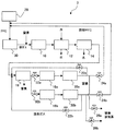
本発明の実施形態に係るガス分離装置の一例の概略を図1に示し、その構成について説明する。ガス分離装置1は、真空ポンプ10と、スクラバ装置12と、脱水装置14と、濃縮手段である濃縮装置16と、分離手段である分離装置18と、吸引手段であるカラム用真空ポンプ20と、バルブ22,24,26とを備える。
An outline of an example of a gas separation apparatus according to an embodiment of the present invention is shown in FIG. The
図1のガス分離装置1において、半導体製造工程、液晶製造工程等のドライエッチングやCVD(化学気相成長法)等の薄膜形成などの製造工程30等に、真空ポンプ10の吸い込み側が接続されており、真空ポンプ10の吐き出し側は、スクラバ装置12の入口に接続されている。スクラバ装置12の出口は、脱水装置14の入口に接続され、脱水装置14の出口は濃縮装置16の入口に接続されている。濃縮装置16の出口は分離装置18の入口に接続され、分離装置18の出口は、カラム用真空ポンプ20の吸い込み側に接続され、このカラム用真空ポンプ20の吐き出し側はバルブ22,24,26を介して、濃縮装置16へのガス導入配管と、製造工程30におけるPFC供給配管と、窒素排気系とにそれぞれ接続されている。
In the
本実施形態に係るガス分離方法及びガス分離装置1の動作について説明する。図1のガス分離装置1において、半導体製造工程、液晶製造工程等のドライエッチングや薄膜形成などの製造工程30には、PFCガス供給装置28からPFCガスが供給される。そこで、PFCガスを含んだ排ガスが生じ、PFCガスを含む排ガスは、真空ポンプ10によって製造工程30から排気される。
The operation of the gas separation method and the
ここで、製造工程30においては、PFCガスが分解してフッ酸(HF)が発生するため、排ガス中にはフッ酸も含まれている。このため、排ガスをそのまま排ガス経路及び真空ポンプ10に導入すると、排ガス経路を腐食するおそれ及び真空ポンプ10を損傷するおそれがある。そこで、真空ポンプ10に至る排ガス経路において、窒素ガス等を希釈ガスとして供給し、排ガスが希釈される。
Here, in the
真空ポンプ10の吐き出し側から排出される、窒素で希釈された排ガスは、スクラバ装置12に供給され、水のシャワーによって、排ガス中のフッ酸(HF)等が除去される。
The exhaust gas diluted with nitrogen and discharged from the discharge side of the
スクラバ装置12からの排ガスは、脱水装置14に導入され、ここで水分が除去される。これは、排ガスがスクラバ装置12において、水分を多く含み、後処理工程のためには、水分を除去しておくことが好ましいからである。なお、ガスの流れ方向に対するスクラバ装置12の上流側あるいは脱水装置14の下流側に微粒子除去フィルタ(図示せず)を設けてもよい。これにより、排ガス中の半導体、無機及び有機の絶縁材料、金属等の微粒子を除去することができる。
The exhaust gas from the
このようにして、得られたPFCガスと窒素とを含む排ガスは、濃縮装置16に供給される。この濃縮装置16は、排ガスを分離装置18に導入する前に窒素をある程度除去するためのものである。これによって、排ガス中から窒素がある程度除去され、PFCガスが濃縮される。
Thus, the obtained exhaust gas containing PFC gas and nitrogen is supplied to the
このようにして、PFCガスを濃縮した後、この被処理ガスは分離装置18に供給される。分離装置18は、内部に所望の充填材を充填したカラムを有し、このカラムの入口からカラム中に被処理ガスが流通される。また、分離装置18のカラムの出口には、カラム用真空ポンプ20の吸い込み側が接続されており、このカラム用真空ポンプ20によりカラム内部は減圧状態になる。これにより、被処理ガスはカラム内部の充填材に接触しながら流通され、被処理ガスに含まれるガス成分毎のリテンションタイム(保持時間)が異なるため、PFCガスと窒素ガスとに分離される。
Thus, after concentrating PFC gas, this to-be-processed gas is supplied to the
一般に窒素は充填材への吸着力が弱いため、PFCガスより早くカラムから流出する。窒素が流出した後、PFCガスを排出させることで、窒素とPFCガスとを分離する。ここで、窒素とPFCとの画分の間に両者が混合された窒素+PFCの画分が生じる場合があるが、この画分は濃縮装置16への流入側に返送すればよい。例えば、カラムをカラム用真空ポンプ20で引きながら、被処理ガスをカラムに所定量流入させ、窒素が含まれている画分と、PFCが含まれている画分を別々に採取し、両者が混合された窒素+PFCの画分は濃縮装置16への流入側に返送する。
In general, nitrogen has a weak adsorption power to the packing material, and therefore flows out of the column earlier than the PFC gas. After the nitrogen flows out, the PFC gas is discharged to separate the nitrogen and the PFC gas. Here, there may be a nitrogen + PFC fraction in which both are mixed between the nitrogen and PFC fractions. This fraction may be returned to the inflow side to the
すなわち、分離装置18のカラムで分離されたPFCが含まれている画分はバルブ24を介してリサイクルされ、製造工程30において再利用される。分離装置18のカラムで分離された窒素が含まれている画分は、バルブ26を介して窒素排気系において排気あるいは製造工程30からの排ガスの希釈等の用途として再利用される。分離装置18のカラムで完全にPFCガスと窒素ガスとに分離されなかった窒素+PFCの画分は濃縮装置16の流入側に返送され、再び濃縮処理及び分離装置18による分離処理がなされる。なお、窒素+PFCの画分はそのPFCの濃度によっては分離装置18の流入側に返送してもよい。
That is, the fraction containing the PFC separated by the column of the
図1において、例えば、SF6及び窒素を含む被処理ガスを、カラム用真空ポンプ20でカラムを減圧状態にしながら分離装置18に間欠的に供給する。一方、分離装置18からは窒素、窒素+SF6、SF6の順序でガスが出てくるため、出口側のバルブ22,24,26を順次切り替えてこれらガスを分離して排出する。すなわち、分離装置18から窒素が排出されるときには、バルブ26を開け、バルブ22及び24を閉じておき、窒素を排気する。また、分離装置18から窒素+SF6が排出されるときには、バルブ22を開け、バルブ24及び26を閉じておき、窒素+SF6は再分離に回す。さらに、分離装置18からSF6が排出されるときには、バルブ24を開け、バルブ22及び26を閉じておき、SF6を製造工程30において再利用する。
In FIG. 1, for example, a gas to be treated containing SF 6 and nitrogen is intermittently supplied to the
なお本実施形態では、分離装置18においては、カラムを減圧状態にし、キャリアガス、すなわち被処理ガスを移送するためのガスを使用しない。通常のガスのカラムクロマト分離では、被処理ガスの移動相として窒素等のキャリアガスを用いる。したがって、被処理ガス中に含まれる複数成分を各成分に分離しても、分離された各成分は多量のキャリアガスの中に含有される形態となっており、分離された各成分を単離するためには、さらに膜分離や深冷分離等の濃縮操作が必要となる。しかし、本実施形態のように被処理ガスを移送するためのガスを使用せずに分離を行うことにより、さらなる濃縮操作は必要なく、容易に被処理ガス中の特定ガスを単離することができる。すなわち、通常のガスのカラムクロマト分離ではキャリアガスを使用するため、分離対象のガスはカラム入口における濃度よりカラム出口における濃度は低くなっているが、本実施形態にかかるガス分離装置及びガス分離方法では、分離対象のガスはカラム入口における濃度よりカラム出口における濃度は高くなっている。
In the present embodiment, in the
本実施形態に係るガス分離装置及びガス分離方法により処理される被処理ガスとしては、あらゆる混合ガスを対象とすることが可能であるが、例えば、半導体製造工程、液晶製造工程等のドライエッチングや薄膜形成などの製造工程、太陽電池の製造工程等で排出される排ガスを対象とする。中でも、半導体製造工程等から排出されるPFCガスを含むガス、特に半導体製造工程等から排出されるPFCガス及び窒素を含むガスを処理対象とすることが好ましい。 The gas to be processed by the gas separation apparatus and the gas separation method according to the present embodiment can be any mixed gas. For example, dry etching such as a semiconductor manufacturing process and a liquid crystal manufacturing process can be used. Exhaust gas discharged from manufacturing processes such as thin film formation and solar cell manufacturing processes is the target. Among them, it is preferable to treat a gas containing PFC gas discharged from a semiconductor manufacturing process or the like, particularly a PFC gas discharged from a semiconductor manufacturing process or the like and a gas containing nitrogen.
被処理ガスに含まれる分離対象(濃縮対象)となる特定ガスとしては、PFCガス、窒素ガス、酸素ガス、水素ガス、ヘリウムガス、アルゴンガス等が挙げられるが、PFCガスであることが好ましい。PFCガスは、C,N,Sのうち少なくとも1つの元素を構成元素とするフッ素化合物のいずれか1つを含み、具体的には、CF4,C2F6,C3F8,CHF3,SF6,NF3またはCOF2のいずれか1つを含む。被処理ガスに含まれる特定ガスは、1種類でも複数種類でもよい。複数種類の特定ガスの分離を行う場合には、充填材やカラムの流通条件等を適宜選択して各特定ガスのリテンションタイムが離れるようにしてやれば、それらを容易に分離することができる。 Examples of the specific gas to be separated (concentrated) included in the gas to be treated include PFC gas, nitrogen gas, oxygen gas, hydrogen gas, helium gas, and argon gas. PFC gas is preferable. The PFC gas contains any one of fluorine compounds containing at least one element of C, N, and S, specifically, CF 4 , C 2 F 6 , C 3 F 8 , and CHF 3. , SF 6 , NF 3 or COF 2 . The specific gas contained in the gas to be processed may be one type or a plurality of types. In the case of separating a plurality of types of specific gases, they can be easily separated by appropriately selecting packing materials and column flow conditions so that the retention times of the specific gases are separated.
スクラバ装置12は、水のシャワーによって、排ガス中のフッ酸(HF)等を水に溶解除去するものであり、公知の装置を用いることができる。
The
脱水装置14としては、どのような形式のものを採用してもよいが、排ガスの温度を低下して水分を除去する形式のものなどが好ましい。
Any type of
濃縮装置16は、排ガスを分離装置18に導入する前に窒素をある程度除去するためのものであり、ガス透過膜を利用した膜分離装置が好ましい。なお、濃縮装置16としては、深冷分離装置を利用することもできる。すなわち、PFCガスと窒素とはその沸点が大きく離れている。そこで、この相違を利用して窒素を容易に分離でき、PFCガスを濃縮することができる。
The
濃縮装置16においては通常、特定ガスの濃度をガス全量に対して80vol%〜90vol%程度に濃縮する。
In the
分離装置18におけるカラムの充填材としては、シリカゲル、活性炭、3A,4A,5A,13X等のモレキュラシーブ、ゼオライト等を用いることができ、被処理ガスに含まれるガスの種類等に応じて充填材を選択すればよい。例えば、被処理ガスがCF4とC2F6との混合ガスの場合は充填剤としてモレキュラシーブ13Xを、被処理ガスがNF3とSF6との混合ガスの場合は充填剤としてモレキュラシーブ13Xを、被処理ガスがCF4とCHF3との混合ガスの場合は充填剤として活性炭を、被処理ガスがCF4とNF3との混合ガスの場合は充填剤として活性炭を、それぞれ用いることにより効果的に分離を行うことができる。
As the column packing material in the
分離装置18のカラムにおける圧力(カラム出口におけるゲージ圧)は大気圧未満であればよいが、具体的には、1000Pa以下、好ましくは100Pa以下、より好ましくは10Pa以下の真空状態とする。カラムにおける減圧度が1000Paを超えると、分離が不十分となる場合がある。また、カラム用真空ポンプ20は、常時作動させておくことが好ましい。
Although the pressure in the column of the separation device 18 (gauge pressure at the column outlet) may be less than atmospheric pressure, specifically, the vacuum state is 1000 Pa or less, preferably 100 Pa or less, more preferably 10 Pa or less. When the degree of vacuum in the column exceeds 1000 Pa, separation may be insufficient. Further, it is preferable that the
分離装置18のカラムにおいて間欠的に供給される被処理ガスの供給流量は、被処理ガスに含まれるガスの種類、カラムの大きさ、カラム温度等の分離条件に応じて決めればよく特に制限はないが、例えば、0.1L/回〜50L/回の範囲である。
The supply flow rate of the gas to be processed that is intermittently supplied to the column of the
分離装置18のカラムにおける被処理ガスの流速は、被処理ガスの種類、カラムの大きさ、カラム温度等の分離条件に応じて決めればよく特に制限はないが、例えば、カラムの長さが1mの場合、0.1SLM(Standard liter per minute)〜50SLMの範囲であり、1SLM〜10SLMの範囲であることが好ましい。
The flow rate of the gas to be processed in the column of the
分離装置18のカラム内部の温度は、被処理ガスに含まれるガスの種類、カラムの大きさ等の分離条件に応じて決めればよく特に制限はないが、20℃〜200℃の範囲であることが好ましく、35℃〜150℃の範囲であることがより好ましい。カラム内部の温度が20℃未満であると、分離が不十分となる場合がある。200℃を超えると、充填材の分解等の可能性がある。
The temperature inside the column of the
また、濃縮装置16と分離装置18との間には被処理ガスを貯留しておくバッファタンクを設置してもよい。バッファタンクは常圧でもよいし、貯留量を増やすために加圧式としてもよい。
Further, a buffer tank for storing the gas to be processed may be installed between the concentrator 16 and the
分離装置18の出口における各成分のガスの採取や、図1におけるバルブ切換は、出口ガスの分析結果に基づき行うことが好ましい。例えば、四重極質量分析計(QMS)、示差熱式検出器(TCD)やフーリエ変換−赤外線分析計(FT−IR)等を用いて、成分を検出し、その結果により制御するとよい。本実施形態では四重極質量分析計(QMS)を用いることが好ましい。また、QMS等の分析結果に基づいてバルブの切り替え条件等をあらかじめ決定しておけば、通常運転時のバルブの切り替え等は時間による制御でかまわない。
The sampling of the gas of each component at the outlet of the
このような処理により、ガスはその成分毎に分離されるため、例えば、PFCガスの画分、窒素の画分においては、他の物質はほとんど含まれない純粋なものが得られる。 As a result of such treatment, the gas is separated into its components. For example, in the PFC gas fraction and the nitrogen fraction, pure substances containing almost no other substances are obtained.
また、分離装置18として、複数のカラムを用意しておき、被処理ガスを各カラムに順次供給し、各画分を各カラムから順次採取することも好ましい。
In addition, it is also preferable to prepare a plurality of columns as the
図2に、2つの分離装置18a、18bを用意しこれらに順次被処理ガスを供給することで、画分を得るための構成例を示す。例えば、SF6及び窒素を含む被処理ガスを、カラム用真空ポンプ20a及び20bでそれぞれカラムを減圧状態にしながら、入口側のバルブ32a,32bを順次切り替えて順次分離装置18a及び18bに流入する。一方、各分離装置18a、18bからは窒素、窒素+SF6、SF6の順序でガスがでてくるため、出口側のバルブ22a,24a,26a及び22b,24b,26bを順次切り替えてこれらガスを分離して排出する。すなわち、分離装置18aから窒素が排出されるときには、バルブ26aを開け、バルブ22a及び24aを閉じておき、窒素を排気する。また、分離装置18aから窒素+SF6が排出されるときには、バルブ22aを開け、バルブ24a及び26aを閉じておき、窒素+SF6は再分離に回す。さらに、分離装置18aからSF6が排出されるときには、バルブ24aを開け、バルブ22a及び26aを閉じておき、SF6を製造工程30において再利用する。一方、分離装置18bから窒素が排出されるときには、バルブ26bを開け、バルブ22b及び24bを閉じておき、窒素を排気する。また、分離装置18bから窒素+SF6が排出されるときには、バルブ22bを開け、バルブ24b及び26bを閉じておき、窒素+SF6は再分離に回す。さらに、分離装置18bからSF6が排出されるときには、バルブ24bを開け、バルブ22b及び26bを閉じておき、SF6を製造工程30において再利用する。
FIG. 2 shows a configuration example for obtaining a fraction by preparing two
このようにして、複数の分離装置18を組み合わせることにより分離の処理効率を向上させることができる。図2では2つの分離装置18及び2つのカラム用真空ポンプ20を使用したが、それぞれ3つ以上を組み合わせてもよく、また、2つの分離装置18及び1つのカラム用真空ポンプ20を使用してもよい。使用する分離装置18及びカラム用真空ポンプ20の数は、分離する成分の数、被処理ガスの処理量等に応じて最適なものを選択すればよい。
In this way, the separation processing efficiency can be improved by combining a plurality of
また、被処理ガスの成分によっては充填材の異なる複数のカラムを直列に接続して使用してもよい。 Further, depending on the component of the gas to be processed, a plurality of columns having different fillers may be connected in series.
本実施形態において、分離装置18の出口において純粋なガス成分を得ることができるが、分離装置18により分離した成分をさらに第2濃縮装置(図示せず)により濃縮してもよい。この第2濃縮装置も上述の濃縮装置16と同じく、膜分離装置や深冷分離装置が用いられる。
In the present embodiment, a pure gas component can be obtained at the outlet of the
このように、本実施形態においては、充填材が充填されたカラムの内部を減圧状態にしながら、被処理ガスを移送するためのガスを使用せずに被処理ガスをカラムに流通させることにより、例えば、SF6等のPFC及び窒素を含む被処理ガス中のPFCの濃縮を容易に高純度で行うことができる。そこで、分離されたSF6等のPFCを回収再利用することができる。このため、特に、原料ガスであるPFCの濃度として99.999%以上の高純度が要求される半導体製造工程、液晶製造工程等においてPFCの回収再利用を行うことができる。 As described above, in the present embodiment, the gas to be processed is circulated through the column without using the gas for transferring the gas to be processed while the inside of the column filled with the filler is in a reduced pressure state. For example, PFC such as SF 6 and PFC in a gas to be treated containing nitrogen can be easily concentrated with high purity. Therefore, the separated PFC such as SF 6 can be recovered and reused. Therefore, in particular, the PFC can be recovered and reused in a semiconductor manufacturing process, a liquid crystal manufacturing process, or the like that requires a high purity of 99.999% or more as the concentration of the PFC that is a raw material gas.
また、本実施形態では、分離装置18の前段に濃縮装置16を設け、一旦窒素を除去しておく。これによって、分離装置18において、PFCを効率よく高濃度で分離することができる。
Moreover, in this embodiment, the
また、濃縮装置16、分離装置18において得られる窒素は、上述したように製造工程30からの排ガスの希釈等の用途として再利用される。この窒素ガスについては、そのまま再利用しても問題はないが、PFCガスが若干含まれている場合には、PFCガスを除去する処理を行ってもよい。この処理としては、従来よりPFCガスの分解方法として知られているプラズマ分解処理、燃焼、触媒加熱処理などが好ましい。さらには、膜処理、深冷分離、カラム分離などを再度行い、PFCガスを分離してから再利用してもよい。
Further, the nitrogen obtained in the
以下、実施例および比較例を挙げ、本発明をより具体的に詳細に説明するが、本発明は、以下の実施例に限定されるものではない。 Hereinafter, although an example and a comparative example are given and the present invention is explained more concretely in detail, the present invention is not limited to the following examples.
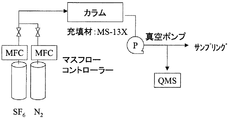
(実施例1)
図3に示す実験装置を使用して、PFCであるSF6と窒素との混合ガス(被処理ガス)の分離を行った。カラムは、内径54.9mm、長さ1.0mのものを1本使用した。カラム温度は120℃とし、充填材としてモレキュラシーブ13X(GLサイエンス社製)を使用した。カラム出口を真空ポンプにて1.0×10⁻³Pa程度の減圧にした状態で、SF6/N2(SF6:0.9SLM、N2:0.1SLM →SF6濃度:90%)の混合ガスを2分間導入した後、ガスの供給を止めて真空ポンプで排気のみを行った。
Example 1
Using the experimental apparatus shown in FIG. 3, a mixed gas (processed gas) of SF 6 which is PFC and nitrogen was separated. One column having an inner diameter of 54.9 mm and a length of 1.0 m was used. The column temperature was 120 ° C., and molecular sieve 13X (manufactured by GL Science) was used as a filler. SF 6 / N 2 (SF 6 : 0.9 SLM, N 2 : 0.1 SLM → SF 6 concentration: 90%) with the column outlet reduced to about 1.0 × 10 −3 Pa by a vacuum pump. After introducing the mixed gas for 2 minutes, the supply of the gas was stopped and only a vacuum pump was used for evacuation.
その結果、最初に窒素が排出され、後半にSF6が排出され、分離されていることが確認された。分析にはQMS(株式会社アルバック製RG−202P(特型)を用いた。QMS分析結果をモニタしながら後半のSF6サンプルを採取し分析をした結果、SF6濃度が99.9%以上であることを確認した。流出ガスのQMSの分析結果を図4に示す。QMSでは分子はイオン化され、N2は質量数28(N2)、SF6はFが1つ取れた質量数127(SF5)の挙動を確認することでカラムからの排出状況及び分離状況がわかる。 As a result, it was confirmed that nitrogen was discharged first and SF 6 was discharged and separated in the second half. QMS (RG-202P (special model) manufactured by ULVAC, Inc. was used for the analysis. As a result of collecting and analyzing the SF 6 sample in the latter half while monitoring the QMS analysis result, the SF 6 concentration was 99.9% or more. The result of QMS analysis of the effluent gas is shown in Fig. 4. In QMS, the molecules are ionized, N 2 has a mass number of 28 (N 2 ), and SF 6 has a mass number of 127 (one F). By confirming the behavior of SF 5 ), the discharge state and separation state from the column can be understood.
(実施例2)
実施例1と同様の装置を使用して、SF6/N2(SF6:0.9SLM、N2:0.1SLM →SF6濃度:90%)の混合ガスをパルス状で4バッチ導入し、1本のカラムで連続処理する試験を行った。カラム出口を真空ポンプによって排気しながら、混合ガスを2分間供給した後、18分間真空ポンプによる排気のみを行い、これを4回繰り返した。1バッチの時間は20分である。
(Example 2)
Using the same apparatus as in Example 1, four batches of SF 6 / N 2 (SF 6 : 0.9 SLM, N 2 : 0.1 SLM → SF 6 concentration: 90%) were introduced in pulses. The test which carries out continuous processing with one column was done. The mixed gas was supplied for 2 minutes while the column outlet was evacuated by a vacuum pump, and then only the evacuation by the vacuum pump was performed for 18 minutes. The time for one batch is 20 minutes.
流出ガスのQMSの分析結果を図5に示す。試験の結果、安定して繰り返し濃縮SF6が得られた。QMS分析結果をモニタしながら後半のSF6サンプルを採取し分析をした結果、実施例1と同様にSF6濃度が99.9%以上であることが分かった。2バッチ目以降の初期に排出される窒素にはカラム内に残留するSF6が混入するが、このガスは分離装置前段の前処理である膜分離装置等の濃縮装置に戻し、原料排ガスと共に窒素を除去することによって再利用可能である。そこでN2除去処理されたガスが再び分離装置に入り高濃度へと濃縮することができる。 FIG. 5 shows the QMS analysis result of the effluent gas. As a result of the test, concentrated SF 6 was obtained stably and repeatedly. As a result of collecting and analyzing the SF 6 sample in the latter half while monitoring the QMS analysis result, it was found that the SF 6 concentration was 99.9% or more as in Example 1. The nitrogen discharged in the initial stage after the second batch contains SF 6 remaining in the column. This gas is returned to a concentrator such as a membrane separator, which is a pretreatment before the separator, and is combined with the raw material exhaust gas. Can be reused by removing. Therefore, the gas that has been subjected to the N 2 removal treatment can enter the separator again and be concentrated to a high concentration.
(実施例3)
図6に示すようなカラムを2本用いた実験装置を用いて、SF6と窒素との混合ガスの分離を行った。実施例2の結果を考慮し、各カラムの出口を2系統設けた。1つはN2がメインの排気系、もう一つがSF6の回収ラインとした。図7のような運転工程表に基づいて分離を行った。混合ガスの供給をカラム入口の切り替えで行い、10分毎に交互に2分間ずつ混合ガスを各カラムに供給した。本実験では、連続供給は行っていないが、供給流速を変化させる(例えば実施例1の5倍の速さ)ことやカラム本数を増やして(例えば5本で)実施することで連続供給も可能である。カラム出口のバルブも10分毎に切り替えた。これによりそれぞれの回収系は区分され、特にSF6回収系には高純度SF6ガスのみが流れることになる。サンプルを採取し分析した結果、実施例1と同様にSF6濃度が99.9%以上であることが分かった。流出ガスのQMSの分析結果を図8に示す。N2排気系のガスは実施例2と同様に分類装置前段の濃縮装置前に戻してN2を除去して再度カラムに通すことで効率良く回収、分離を行うことができる。
(Example 3)
A mixed gas of SF 6 and nitrogen was separated using an experimental apparatus using two columns as shown in FIG. Considering the result of Example 2, two outlets for each column were provided. One was N 2 as the main exhaust system, and the other was the SF 6 recovery line. Separation was performed based on the operation process chart as shown in FIG. The mixed gas was supplied by switching the column inlet, and the mixed gas was alternately supplied to each column every 10 minutes for 2 minutes. In this experiment, continuous supply is not performed, but continuous supply is possible by changing the supply flow rate (for example, 5 times faster than Example 1) or increasing the number of columns (for example, 5 columns). It is. The valve at the column outlet was also switched every 10 minutes. As a result, the respective recovery systems are divided, and in particular, only high-purity SF 6 gas flows through the SF 6 recovery system. As a result of collecting and analyzing a sample, it was found that the SF 6 concentration was 99.9% or more as in Example 1. FIG. 8 shows the QMS analysis result of the effluent gas. The gas in the N 2 exhaust system can be efficiently recovered and separated by returning to the front of the concentrator before the classification apparatus in the same manner as in Example 2 to remove N 2 and passing it again through the column.
(比較例1)膜濃縮装置との比較
一般的なPFC膜濃縮技術の例として、2002年3月に株式会社半導体先端テクノロジーズ(通称Selete)より報告されている膜濃縮方法にて混合ガスの分離を行ったところ、SF6濃度は91%であった。
(Comparative example 1) Comparison with membrane concentrator As an example of a general PFC membrane concentrating technology, separation of mixed gas by the membrane concentrating method reported in March 2002 by Semiconductor Leading Edge Technologies (commonly known as Selete) As a result, SF 6 concentration was 91%.
実施例1〜3のように、SF6及びN2を含む混合ガスの濃縮の際に、被処理ガスを移送するためのガスを使用せずに、カラム出口を減圧状態にしながらカラムに混合ガスを供給することで、SF6とN2とを分離させSF6を99.9%以上の高純度で濃縮することができた。この方法は装置も小型で安価であり、且つ濃縮後の濃度も高いことから非常に有効である。また負圧で運転されるためガスの系外への拡散を防ぐことができ、加圧運転に比べ安全運転が出来る。また複数の分離装置(カラム)を使用して、これらカラムを順次利用することにより、被処理ガスを効率的に連続的に処理することができる。 As in Examples 1 to 3, when the mixed gas containing SF 6 and N 2 is concentrated, the mixed gas is applied to the column while the column outlet is in a reduced pressure state without using the gas for transferring the gas to be processed. Was able to separate SF 6 and N 2 and to concentrate SF 6 with a high purity of 99.9% or more. This method is very effective because the apparatus is small and inexpensive, and the concentration after concentration is high. In addition, since it is operated at a negative pressure, it is possible to prevent the gas from diffusing outside the system, and a safe operation can be performed as compared with a pressurizing operation. In addition, by using a plurality of separation devices (columns) and sequentially using these columns, the gas to be processed can be processed efficiently and continuously.
1,3 ガス分離装置、10 真空ポンプ、12 スクラバ装置、14 脱水装置、16 濃縮装置、18,18a,18b 分離装置、 20,20a,20b カラム用真空ポンプ、22,22a,22b,24,24a,24b,26,26a,26b,32a,32b バルブ、28 PFCガス供給装置、30 製造工程。
1,3 Gas separation device, 10 Vacuum pump, 12 Scrubber device, 14 Dehydration device, 16 Concentration device, 18, 18a, 18b Separation device, 20, 20a, 20b Column vacuum pump, 22, 22a, 22b, 24,
Claims (18)
充填材が充填されたカラムを利用して、前記特定ガスを他のガスから分離する分離手段と、
前記カラム内部を減圧状態にする吸引手段と、
を有し、
前記分離手段において、前記被処理ガスを移送するためのガスを使用せずに前記特定ガスを分離し、
前記カラム内部の圧力が1000Pa以下であることを特徴とするガス分離装置。 A gas separation device for separating a specific gas from a gas to be treated containing a specific gas of at least one component,
Separation means for separating the specific gas from other gases using a column filled with a filler;
Suction means for reducing the pressure inside the column;
Have
In the separation means, the specific gas is separated without using a gas for transferring the gas to be treated ;
A gas separation apparatus, wherein the pressure inside the column is 1000 Pa or less .
前記被処理ガス中の前記特定ガスの濃度を濃縮する濃縮手段をさらに有することを特徴とするガス分離装置。 The gas separation device according to claim 1 ,
The gas separation apparatus further comprising a concentrating means for concentrating the concentration of the specific gas in the gas to be treated.
前記分離手段から排出される未分離の被処理ガスを、前記分離手段あるいは前記濃縮手段に返送する返送手段をさらに有することを特徴とするガス分離装置。 The gas separation device according to claim 1 or 2 ,
The gas separation apparatus further comprising a return means for returning the unseparated gas to be treated discharged from the separation means to the separation means or the concentration means.
前記分離されたガス中の前記特定ガスの濃度を濃縮する第2濃縮手段をさらに有することを特徴とするガス分離装置。 The gas separator according to any one of claims 1 to 3 ,
The gas separation device further comprising a second concentration means for concentrating the concentration of the specific gas in the separated gas.
前記特定ガスはPFCガスであることを特徴とするガス分離装置。 The gas separation device according to any one of claims 1 to 4 ,
The gas separator according to claim 1, wherein the specific gas is PFC gas.
前記PFCガスは、C,N,Sのうち少なくとも1つの元素を構成元素とするフッ素化合物のいずれか1つを含むことを特徴とすることを特徴とするガス分離装置。 The gas separation device according to claim 5 ,
The PFC gas includes any one of fluorine compounds containing at least one element of C, N, and S as a constituent element.
前記PFCガスは、CF4,C2F6,C3F8,CHF3,SF6,NF3またはCOF2のいずれか1つを含むことを特徴とするガス分離装置。 The gas separation device according to claim 6 ,
The gas separation apparatus according to claim 1, wherein the PFC gas includes any one of CF 4 , C 2 F 6 , C 3 F 8 , CHF 3 , SF 6 , NF 3, and COF 2 .
前記被処理ガスは、窒素を含むことを特徴とするガス分離装置。 A gas separation device according to any one of claims 5 to 7 ,
The gas to be treated includes nitrogen.
前記PFCガスはSF6であり、前記充填材はモレキュラシーブ13Xであることを特徴とするガス分離装置。 The gas separation device according to claim 8 ,
The PFC gas is SF 6 and the filler is a molecular sieve 13X.
前記分離手段において複数のカラムを使用して、これら複数のカラムを順次利用することを特徴とするガス分離装置。 A gas separation apparatus according to any one of claims 1 to 9
A gas separation apparatus characterized by using a plurality of columns in the separation means and sequentially using the plurality of columns.
前記分離手段を複数有し、前記複数の分離手段が直列に接続されていることを特徴とするガス分離装置。 It is a gas separation device given in any 1 paragraph of Claims 1-10 ,
A gas separation apparatus comprising a plurality of the separation means, wherein the plurality of separation means are connected in series.
充填剤が異なる複数の分離手段が直列に接続されていることを特徴とするガス分離装置。 A gas separation device according to claim 11 , comprising:
A gas separation device, wherein a plurality of separation means having different fillers are connected in series.
充填材が充填されたカラムの内部を減圧状態にしながら前記被処理ガスを前記カラムに流通させて、前記特定ガスを他のガスから分離する分離工程を含み、
前記分離工程において、前記被処理ガスを移送するためのガスを使用せず、
前記カラム内部の圧力が1000Pa以下であることを特徴とするガス分離方法。 A gas separation method for separating a specific gas from a gas to be treated containing a specific gas of at least one component,
A separation step of separating the specific gas from other gases by circulating the gas to be treated through the column while reducing the pressure inside the column filled with a packing material;
In the separation step, a gas for transferring the gas to be treated is not used ,
A gas separation method, wherein the pressure inside the column is 1000 Pa or less .
前記分離工程の前に前記被処理ガス中の特定ガスの濃度を濃縮する濃縮工程をさらに含むことを特徴とするガス分離方法。 A gas separation method according to claim 13 ,
A gas separation method further comprising a concentration step of concentrating the concentration of the specific gas in the gas to be treated before the separation step.
前記分離工程から排出される未分離の被処理ガスを、前記分離工程あるいは前記濃縮工程に返送する返送工程をさらに含むことを特徴とするガス分離方法。 The gas separation method according to claim 13 or 14 ,
A gas separation method, further comprising a return step of returning the unseparated gas to be processed discharged from the separation step to the separation step or the concentration step.
前記分離工程の後に前記分離されたガス中の前記特定ガスの濃度を濃縮する第2濃縮工程をさらに含むことを特徴とするガス分離方法。 The gas separation method according to any one of claims 13 to 15 , comprising:
The gas separation method further comprising a second concentration step of concentrating the concentration of the specific gas in the separated gas after the separation step.
前記分離工程において、直列に接続された複数のカラムを用いることを特徴とするガス分離方法。 The gas separation method according to any one of claims 13 to 16 , comprising:
In the separation step, a plurality of columns connected in series are used.
前記分離工程において、直列に接続された、充填剤が異なる複数のカラムを用いることを特徴とするガス分離方法。 The gas separation method according to claim 17 ,
In the separation step, a plurality of columns connected in series and having different packing materials are used.
Priority Applications (6)
| Application Number | Priority Date | Filing Date | Title |
|---|---|---|---|
| JP2005120668A JP4212106B2 (en) | 2005-04-19 | 2005-04-19 | Gas separation device and gas separation method |
| US11/912,125 US7892322B2 (en) | 2005-04-19 | 2006-04-19 | Apparatus and method for separating gas |
| KR1020077026882A KR20080011205A (en) | 2005-04-19 | 2006-04-19 | Apparatus and method for separating gas |
| TW095113893A TWI359691B (en) | 2005-04-19 | 2006-04-19 | Gas separating device and gas separating method |
| EP06732104A EP1872847A4 (en) | 2005-04-19 | 2006-04-19 | Apparatus and method for separating gas |
| PCT/JP2006/308197 WO2006112472A1 (en) | 2005-04-19 | 2006-04-19 | Apparatus and method for separating gas |
Applications Claiming Priority (1)
| Application Number | Priority Date | Filing Date | Title |
|---|---|---|---|
| JP2005120668A JP4212106B2 (en) | 2005-04-19 | 2005-04-19 | Gas separation device and gas separation method |
Publications (3)
| Publication Number | Publication Date |
|---|---|
| JP2006297245A JP2006297245A (en) | 2006-11-02 |
| JP2006297245A5 JP2006297245A5 (en) | 2007-09-20 |
| JP4212106B2 true JP4212106B2 (en) | 2009-01-21 |
Family
ID=37115186
Family Applications (1)
| Application Number | Title | Priority Date | Filing Date |
|---|---|---|---|
| JP2005120668A Expired - Fee Related JP4212106B2 (en) | 2005-04-19 | 2005-04-19 | Gas separation device and gas separation method |
Country Status (6)
| Country | Link |
|---|---|
| US (1) | US7892322B2 (en) |
| EP (1) | EP1872847A4 (en) |
| JP (1) | JP4212106B2 (en) |
| KR (1) | KR20080011205A (en) |
| TW (1) | TWI359691B (en) |
| WO (1) | WO2006112472A1 (en) |
Families Citing this family (10)
| Publication number | Priority date | Publication date | Assignee | Title |
|---|---|---|---|---|
| JP2009018269A (en) * | 2007-07-12 | 2009-01-29 | Japan Organo Co Ltd | Gas separation apparatus and gas separation method |
| JP2012194042A (en) * | 2011-03-16 | 2012-10-11 | Taiyo Nippon Sanso Corp | Preprocessing apparatus for gas analyzer |
| TWI490029B (en) * | 2012-07-20 | 2015-07-01 | Kern Energy Entpr Co Ltd | Gas recovering system |
| KR20150026707A (en) | 2013-08-30 | 2015-03-11 | 주식회사 코캣 | Device and method for recovering low concentration sulfur hexafluoride gas |
| US11247015B2 (en) | 2015-03-24 | 2022-02-15 | Ventec Life Systems, Inc. | Ventilator with integrated oxygen production |
| US10315002B2 (en) | 2015-03-24 | 2019-06-11 | Ventec Life Systems, Inc. | Ventilator with integrated oxygen production |
| US10773049B2 (en) | 2016-06-21 | 2020-09-15 | Ventec Life Systems, Inc. | Cough-assist systems with humidifier bypass |
| US11191915B2 (en) | 2018-05-13 | 2021-12-07 | Ventec Life Systems, Inc. | Portable medical ventilator system using portable oxygen concentrators |
| KR20210014577A (en) * | 2019-07-29 | 2021-02-09 | 에이에스엠 아이피 홀딩 비.브이. | Method of forming a structure using fluorine removal |
| GB2588908B (en) * | 2019-11-13 | 2022-04-20 | Edwards Ltd | Inert gas recovery from a semiconductor manufacturing tool |
Family Cites Families (18)
| Publication number | Priority date | Publication date | Assignee | Title |
|---|---|---|---|---|
| US4194892A (en) * | 1978-06-26 | 1980-03-25 | Union Carbide Corporation | Rapid pressure swing adsorption process with high enrichment factor |
| JPH07100604B2 (en) | 1986-09-12 | 1995-11-01 | 日本酸素株式会社 | Neon and helium manufacturing method |
| JP2848557B2 (en) | 1987-06-18 | 1999-01-20 | 三菱瓦斯化学株式会社 | Hydrogen purification method |
| JP3210812B2 (en) | 1994-10-07 | 2001-09-25 | 日本原子力研究所 | Method and apparatus for separating hydrogen isotope and helium |
| JP2741743B2 (en) | 1994-11-17 | 1998-04-22 | 工業技術院長 | High temperature separation of carbon dioxide |
| US5840953A (en) | 1995-11-16 | 1998-11-24 | Eagle-Picher Industries, Inc. | Purified tetraethoxysilane and method of purifying |
| US5626033A (en) * | 1996-07-12 | 1997-05-06 | The Boc Group, Inc. | Process for the recovery of perfluorinated compounds |
| US5720797A (en) * | 1996-12-18 | 1998-02-24 | Alliedsignal Inc. | Process for recovering sulfur hexafluoride |
| JP3654477B2 (en) | 1997-02-17 | 2005-06-02 | 独立行政法人科学技術振興機構 | Bulk separation of gases by parametric gas chromatography. |
| JP3356965B2 (en) * | 1997-06-20 | 2002-12-16 | 株式会社日立製作所 | SF6 gas recovery / purification processing apparatus and method |
| US5976222A (en) * | 1998-03-23 | 1999-11-02 | Air Products And Chemicals, Inc. | Recovery of perfluorinated compounds from the exhaust of semiconductor fabs using membrane and adsorption in series |
| DE19910678A1 (en) * | 1998-08-20 | 2000-09-14 | Solvay Fluor & Derivate | Process for the purification of SF¶6¶ contaminated gases |
| EP1048337A1 (en) * | 1999-04-28 | 2000-11-02 | Air Products And Chemicals, Inc. | Recovery of perfluorinated compounds from the exhaust of semiconductors fabrications with recycle of vaccum pump dilutent |
| CN1241672C (en) * | 2000-05-26 | 2006-02-15 | 昭和电工株式会社 | Harn-removing agent and method for rendering halogen-containing gas harmless and uses thereof |
| JP2002035528A (en) * | 2000-07-26 | 2002-02-05 | Japan Atom Energy Res Inst | Gas separation apparatus |
| JP5093635B2 (en) | 2001-03-21 | 2012-12-12 | 独立行政法人日本原子力研究開発機構 | Gas separator |
| JP4538622B2 (en) | 2003-07-29 | 2010-09-08 | オルガノ株式会社 | Gas separator |
| JP2009018269A (en) * | 2007-07-12 | 2009-01-29 | Japan Organo Co Ltd | Gas separation apparatus and gas separation method |
-
2005
- 2005-04-19 JP JP2005120668A patent/JP4212106B2/en not_active Expired - Fee Related
-
2006
- 2006-04-19 KR KR1020077026882A patent/KR20080011205A/en not_active Application Discontinuation
- 2006-04-19 WO PCT/JP2006/308197 patent/WO2006112472A1/en active Application Filing
- 2006-04-19 EP EP06732104A patent/EP1872847A4/en not_active Withdrawn
- 2006-04-19 TW TW095113893A patent/TWI359691B/en not_active IP Right Cessation
- 2006-04-19 US US11/912,125 patent/US7892322B2/en not_active Expired - Fee Related
Also Published As
| Publication number | Publication date |
|---|---|
| JP2006297245A (en) | 2006-11-02 |
| US7892322B2 (en) | 2011-02-22 |
| TW200706232A (en) | 2007-02-16 |
| KR20080011205A (en) | 2008-01-31 |
| EP1872847A4 (en) | 2010-04-21 |
| WO2006112472A1 (en) | 2006-10-26 |
| US20090056540A1 (en) | 2009-03-05 |
| EP1872847A1 (en) | 2008-01-02 |
| TWI359691B (en) | 2012-03-11 |
Similar Documents
| Publication | Publication Date | Title |
|---|---|---|
| JP4212106B2 (en) | Gas separation device and gas separation method | |
| KR101107196B1 (en) | Apparatus and method for separating gas | |
| EP1175933B1 (en) | Gas separation apparatus | |
| JP3152389B2 (en) | Separation and recovery method of fluorochemical by membrane | |
| JP4683543B2 (en) | Gas separation method and gas separation apparatus | |
| US6530980B2 (en) | Gas separation apparatus | |
| JP5093635B2 (en) | Gas separator | |
| JP2019195758A (en) | Gas separator and gas separation method | |
| JP4538622B2 (en) | Gas separator | |
| JP4787550B2 (en) | Gas separation method and gas separation apparatus | |
| KR101420767B1 (en) | Appratus for enriching and recovering fluorinated gas using membrane, and the method for enriching and recoverying of fluorinated gas thereby | |
| JP4683544B2 (en) | Gas separation method and gas separation apparatus | |
| US6702874B2 (en) | Gas separation apparatus and gas separation method | |
| KR20140014542A (en) | Appratus for separating and enriching fluorinated gas, and the method for separating and enriching of fluorinated gas thereby | |
| JP2000005561A (en) | Treatment of fluoride | |
| JP2005046746A (en) | Gas separation apparatus | |
| JP6084830B2 (en) | Perfluorocompound exhaust gas detoxification treatment apparatus and method | |
| JP2020006324A (en) | Gas separator and gas separation method |
Legal Events
| Date | Code | Title | Description |
|---|---|---|---|
| A521 | Written amendment |
Free format text: JAPANESE INTERMEDIATE CODE: A523 Effective date: 20070802 |
|
| A621 | Written request for application examination |
Free format text: JAPANESE INTERMEDIATE CODE: A621 Effective date: 20071129 |
|
| A131 | Notification of reasons for refusal |
Free format text: JAPANESE INTERMEDIATE CODE: A131 Effective date: 20080408 |
|
| A521 | Written amendment |
Free format text: JAPANESE INTERMEDIATE CODE: A523 Effective date: 20080603 |
|
| TRDD | Decision of grant or rejection written | ||
| A01 | Written decision to grant a patent or to grant a registration (utility model) |
Free format text: JAPANESE INTERMEDIATE CODE: A01 Effective date: 20081007 |
|
| A01 | Written decision to grant a patent or to grant a registration (utility model) |
Free format text: JAPANESE INTERMEDIATE CODE: A01 |
|
| A61 | First payment of annual fees (during grant procedure) |
Free format text: JAPANESE INTERMEDIATE CODE: A61 Effective date: 20081027 |
|
| FPAY | Renewal fee payment (event date is renewal date of database) |
Free format text: PAYMENT UNTIL: 20111107 Year of fee payment: 3 |
|
| R150 | Certificate of patent or registration of utility model |
Free format text: JAPANESE INTERMEDIATE CODE: R150 |
|
| S111 | Request for change of ownership or part of ownership |
Free format text: JAPANESE INTERMEDIATE CODE: R313117 |
|
| FPAY | Renewal fee payment (event date is renewal date of database) |
Free format text: PAYMENT UNTIL: 20111107 Year of fee payment: 3 |
|
| R350 | Written notification of registration of transfer |
Free format text: JAPANESE INTERMEDIATE CODE: R350 |
|
| FPAY | Renewal fee payment (event date is renewal date of database) |
Free format text: PAYMENT UNTIL: 20111107 Year of fee payment: 3 |
|
| FPAY | Renewal fee payment (event date is renewal date of database) |
Free format text: PAYMENT UNTIL: 20121107 Year of fee payment: 4 |
|
| FPAY | Renewal fee payment (event date is renewal date of database) |
Free format text: PAYMENT UNTIL: 20121107 Year of fee payment: 4 |
|
| FPAY | Renewal fee payment (event date is renewal date of database) |
Free format text: PAYMENT UNTIL: 20131107 Year of fee payment: 5 |
|
| R250 | Receipt of annual fees |
Free format text: JAPANESE INTERMEDIATE CODE: R250 |
|
| LAPS | Cancellation because of no payment of annual fees |