EP0885651A1 - Mixer - Google Patents
Mixer Download PDFInfo
- Publication number
- EP0885651A1 EP0885651A1 EP97810383A EP97810383A EP0885651A1 EP 0885651 A1 EP0885651 A1 EP 0885651A1 EP 97810383 A EP97810383 A EP 97810383A EP 97810383 A EP97810383 A EP 97810383A EP 0885651 A1 EP0885651 A1 EP 0885651A1
- Authority
- EP
- European Patent Office
- Prior art keywords
- mixer
- components
- dividing edge
- end plate
- mixer element
- Prior art date
- Legal status (The legal status is an assumption and is not a legal conclusion. Google has not performed a legal analysis and makes no representation as to the accuracy of the status listed.)
- Granted
Links
- 230000000903 blocking effect Effects 0.000 claims description 2
- 239000000463 material Substances 0.000 abstract description 8
- 239000000203 mixture Substances 0.000 description 4
- 230000008878 coupling Effects 0.000 description 3
- 238000010168 coupling process Methods 0.000 description 3
- 238000005859 coupling reaction Methods 0.000 description 3
- 238000000034 method Methods 0.000 description 2
- 230000000712 assembly Effects 0.000 description 1
- 238000000429 assembly Methods 0.000 description 1
- 239000003054 catalyst Substances 0.000 description 1
- 239000007795 chemical reaction product Substances 0.000 description 1
- 230000002950 deficient Effects 0.000 description 1
- 239000004848 polyfunctional curative Substances 0.000 description 1
- 230000002787 reinforcement Effects 0.000 description 1
- 238000000926 separation method Methods 0.000 description 1
Images

Classifications
-
- B—PERFORMING OPERATIONS; TRANSPORTING
- B05—SPRAYING OR ATOMISING IN GENERAL; APPLYING FLUENT MATERIALS TO SURFACES, IN GENERAL
- B05C—APPARATUS FOR APPLYING FLUENT MATERIALS TO SURFACES, IN GENERAL
- B05C17/00—Hand tools or apparatus using hand held tools, for applying liquids or other fluent materials to, for spreading applied liquids or other fluent materials on, or for partially removing applied liquids or other fluent materials from, surfaces
- B05C17/005—Hand tools or apparatus using hand held tools, for applying liquids or other fluent materials to, for spreading applied liquids or other fluent materials on, or for partially removing applied liquids or other fluent materials from, surfaces for discharging material from a reservoir or container located in or on the hand tool through an outlet orifice by pressure without using surface contacting members like pads or brushes
- B05C17/00553—Hand tools or apparatus using hand held tools, for applying liquids or other fluent materials to, for spreading applied liquids or other fluent materials on, or for partially removing applied liquids or other fluent materials from, surfaces for discharging material from a reservoir or container located in or on the hand tool through an outlet orifice by pressure without using surface contacting members like pads or brushes with means allowing the stock of material to consist of at least two different components
-
- B—PERFORMING OPERATIONS; TRANSPORTING
- B01—PHYSICAL OR CHEMICAL PROCESSES OR APPARATUS IN GENERAL
- B01F—MIXING, e.g. DISSOLVING, EMULSIFYING OR DISPERSING
- B01F25/00—Flow mixers; Mixers for falling materials, e.g. solid particles
- B01F25/40—Static mixers
- B01F25/42—Static mixers in which the mixing is affected by moving the components jointly in changing directions, e.g. in tubes provided with baffles or obstructions
- B01F25/43—Mixing tubes, e.g. wherein the material is moved in a radial or partly reversed direction
- B01F25/431—Straight mixing tubes with baffles or obstructions that do not cause substantial pressure drop; Baffles therefor
- B01F25/4314—Straight mixing tubes with baffles or obstructions that do not cause substantial pressure drop; Baffles therefor with helical baffles
- B01F25/43141—Straight mixing tubes with baffles or obstructions that do not cause substantial pressure drop; Baffles therefor with helical baffles composed of consecutive sections of helical formed elements
-
- B—PERFORMING OPERATIONS; TRANSPORTING
- B01—PHYSICAL OR CHEMICAL PROCESSES OR APPARATUS IN GENERAL
- B01F—MIXING, e.g. DISSOLVING, EMULSIFYING OR DISPERSING
- B01F33/00—Other mixers; Mixing plants; Combinations of mixers
- B01F33/50—Movable or transportable mixing devices or plants
- B01F33/501—Movable mixing devices, i.e. readily shifted or displaced from one place to another, e.g. portable during use
- B01F33/5011—Movable mixing devices, i.e. readily shifted or displaced from one place to another, e.g. portable during use portable during use, e.g. hand-held
-
- B—PERFORMING OPERATIONS; TRANSPORTING
- B01—PHYSICAL OR CHEMICAL PROCESSES OR APPARATUS IN GENERAL
- B01F—MIXING, e.g. DISSOLVING, EMULSIFYING OR DISPERSING
- B01F35/00—Accessories for mixers; Auxiliary operations or auxiliary devices; Parts or details of general application
- B01F35/50—Mixing receptacles
- B01F35/52—Receptacles with two or more compartments
- B01F35/522—Receptacles with two or more compartments comprising compartments keeping the materials to be mixed separated until the mixing is initiated
-
- B—PERFORMING OPERATIONS; TRANSPORTING
- B01—PHYSICAL OR CHEMICAL PROCESSES OR APPARATUS IN GENERAL
- B01F—MIXING, e.g. DISSOLVING, EMULSIFYING OR DISPERSING
- B01F2101/00—Mixing characterised by the nature of the mixed materials or by the application field
- B01F2101/2305—Mixers of the two-component package type, i.e. where at least two components are separately stored, and are mixed in the moment of application
-
- B—PERFORMING OPERATIONS; TRANSPORTING
- B05—SPRAYING OR ATOMISING IN GENERAL; APPLYING FLUENT MATERIALS TO SURFACES, IN GENERAL
- B05C—APPARATUS FOR APPLYING FLUENT MATERIALS TO SURFACES, IN GENERAL
- B05C17/00—Hand tools or apparatus using hand held tools, for applying liquids or other fluent materials to, for spreading applied liquids or other fluent materials on, or for partially removing applied liquids or other fluent materials from, surfaces
- B05C17/005—Hand tools or apparatus using hand held tools, for applying liquids or other fluent materials to, for spreading applied liquids or other fluent materials on, or for partially removing applied liquids or other fluent materials from, surfaces for discharging material from a reservoir or container located in or on the hand tool through an outlet orifice by pressure without using surface contacting members like pads or brushes
- B05C17/00503—Details of the outlet element
- B05C17/00506—Means for connecting the outlet element to, or for disconnecting it from, the hand tool or its container
-
- B—PERFORMING OPERATIONS; TRANSPORTING
- B05—SPRAYING OR ATOMISING IN GENERAL; APPLYING FLUENT MATERIALS TO SURFACES, IN GENERAL
- B05C—APPARATUS FOR APPLYING FLUENT MATERIALS TO SURFACES, IN GENERAL
- B05C17/00—Hand tools or apparatus using hand held tools, for applying liquids or other fluent materials to, for spreading applied liquids or other fluent materials on, or for partially removing applied liquids or other fluent materials from, surfaces
- B05C17/005—Hand tools or apparatus using hand held tools, for applying liquids or other fluent materials to, for spreading applied liquids or other fluent materials on, or for partially removing applied liquids or other fluent materials from, surfaces for discharging material from a reservoir or container located in or on the hand tool through an outlet orifice by pressure without using surface contacting members like pads or brushes
- B05C17/00503—Details of the outlet element
- B05C17/00516—Shape or geometry of the outlet orifice or the outlet element
Definitions
- the present invention refers to a mixer for a multiple component dispensing cartridge or dispensing appliance according to the introduction of claim 1.
- Such mixers are known and they have the function of intimately mixing the components in order to prepare them for their application.
- the dividing edge is the first edge where the united material streams are first divided for being mixed together.
- the partial flow "A" precedes and a proper mixture cannot be achieved in the correct volumetric ratio, thus the components cannot properly react with each other resulting in defective bonds, seals, joints, impressions, etc.
- the "B” component is generally a hardener or catalyst, a mixture with an insufficient amount of "B” component is useless and because of this it is common practice, in order to stabilize the desired proportions of the components, to dispense and discard a certain quantity of material before being able to start the proper application of the mixture. Besides wastage of material, the initially dispensed material may not harden and may additionally cause disposal problems. If used, however, it may cause end product failure.
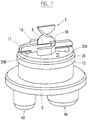
- Fig. 1 shows in a perspective view the inlet portion of a mixer according to the invention, the mixer elements and other parts of the device will be explained with the aid of Figs. 2 to 5.
- the components have a ratio which is differing from 1:1 and the larger component "A” flows out of the divided inlet opening 20A around baffle 16 to the second divided inlet opening 20B and merges with, and carries with it, the smaller component "B” coming out of divided inlet opening 20B, both streams arriving at both sides of the dividing edge 8 of the first mixer element of the mixer element group 3.
- the dividing edge is the dividing edge of the first mixer element of the mixer element group.
- the dividing edge can also be a short dividing wall either attached to a separating ridge or to the first mixer element or to both.
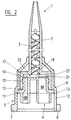
- Fig. 2 shows a mixer 1 comprising a mixer housing 2 containing a mixer element group 3 consisting of helical mixer elements, an inlet section 4 and a coupling ring 5 for fastening the mixer to a two component cartridge with bayonet fastening means 6 and 7.
- the inlet section 4 comprises an inlet 4A for a larger component "A” and a smaller inlet 4B for a smaller component "B". Both components arrive at the dividing edge 8 of the first mixer element of the mixer element group 3.
- the inlet section 4 comprises further a flange 9, the upper side of which is directed towards the mixer element group and fits against the inlet end 10 of the mixer housing 2 and an inner shoulder 11 of the wall 12 of the coupling ring.
- the outer diameter of the inlet section 4 further comprises a retaining flange 14 held in a groove 15 in the mixer housing.
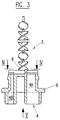
- Fig. 4 shows a main feature of the invention whereby both components are forced, on both sides of separating ridge 17, to flow along the surface 19 formed by the top of the end plate 20 which closes off the merging chamber 23 at the inlet side.
- the larger component "A” flows out of larger inlet 4A through divided inlet opening 20A and is directed towards the divided inlet opening 20B of smaller inlet 4B for the smaller component "B". This occurs, in an indirect way, on both sides of the separating ridge 17 around the arms of a U-shaped baffle 16 and back within the open baffle arms, carrying with it the second component "B" towards the dividing edge 8 of the first mixer element.
- a separating ridge 17 across the surface 19 of the end plate 20 in line with the dividing edge 8 of the first mixer element, the separating ridge 17 having the same height as the baffle.
- a blocking means 18 is located on top of the baffle, partially closing off the cross section of the housing 2 of the mixer element group for preventing component "A" from flowing directly to the dividing edge of the first mixer element.
- the profile of the separating ridge 17 is in the area of the divided inlet openings, and tapered toward the bottom for better flow separation of the material.
- the mixer housing encloses the top surface 19 of the inlet section at the periphery by the internal face 21 of a step 22 in the wall of the mixer housing at the level of the top of the baffle and separating ridge, thus forming a space in the form of merging chamber 23 so that the components are forced to follow the prescribed path parallel to the top surface and perpendicular to the flow direction of the material which leads to the dividing edge 8 of the first mixer element of the mixer element group 3 within the mixer housing.
Landscapes
- Chemical & Material Sciences (AREA)
- Chemical Kinetics & Catalysis (AREA)
- Dispersion Chemistry (AREA)
- Engineering & Computer Science (AREA)
- Mechanical Engineering (AREA)
- Details Of Rigid Or Semi-Rigid Containers (AREA)
- Processing And Handling Of Plastics And Other Materials For Molding In General (AREA)
- Accessories For Mixers (AREA)
- Infusion, Injection, And Reservoir Apparatuses (AREA)
Abstract
Description
- Fig. 1
- shows in a perspective view the inlet portion of a mixer according to the invention,
- Fig. 2
- shows in a longitudinal section the mixer of Fig. 1,
- Fig. 3
- shows in a cross section according to line III-III of Fig. 4 a detail of Fig. 2,
- Fig. 4
- shows a cross-section according to line IV-IV in Fig. 3, and
- Fig. 5
- shows a view in direction of the arrow V in Fig. 3.
Claims (5)
- A mixer for a multiple component dispensing cartridge or appliance, having at least two storage cylinders and comprising a mixer housing (2) containing a mixer element group (3) and being attachable to the dispensing cartridge or appliance, an inlet section (4) comprising side by side separate inlets (4A, 4B) communicating with the dividing edge (8) of the first element of the mixer element group (3), characterized in that the inlet section (4) ends with an end plate (20) having inlet openings (20A, 20B) for the components (A, B) to flow through and that between the top surface (19) of the end plate (20) and the mixer housing (2) a space is formed, for forcing the components to flow substantially perpendicular to the longitudinal mixer axis and parallel to the top surface (19) of the end plate (20) towards a dividing edge (8), the inlet openings (20A, 20B) being arranged on both sides and in line with the dividing edge (8).
- A mixer according to claim 1, characterized in that the space is a merging chamber (23) which is formed by the top surface (19) of the end plate (20) and the internal face (21) of a step (22) of the mixer housing (2).
- A mixer according to claim 1 or 2, characterized in that the space being a merging chamber (23) contains means (16, 18) for deflecting and guiding the flow of the components (A, B) and a separating ridge (17) arranged across the top surface (19) of the end plate (20) and dividing the inlet openings (20A, 20B) for the components (A, B), the separating ridge (17) being in line with the dividing edge (8).
- A mixer according to any of claims 1 to 3 for a dispensing cartridge or appliance with storage cylinders whose volumetric ratio is other than 1:1, characterized in that the separated inlets (4A, 4B) and the inlet openings (20A, 20B) have a different size and that the deflecting and guiding means comprises a U-shaped baffle (16) opened towards the smaller inlet opening (20B) and a partial blocking means (18) on top of the baffle for forcing the component (A) coming out of the larger inlet opening (20A) to flow toward the smaller inlet opening (20B) and into the open arms of the U-shaped baffle (16) before reaching the dividing edge (8), carrying with it the component (B) flowing out of the smaller inlet opening (20B).
- A mixer according to any of claims 1 to 4, characterized in that the dividing edge (8) is the dividing edge of the first mixer element of the mixer element group (3).
Priority Applications (5)
| Application Number | Priority Date | Filing Date | Title |
|---|---|---|---|
| EP97810383A EP0885651B1 (en) | 1997-06-18 | 1997-06-18 | Mixer |
| DE69716887T DE69716887T2 (en) | 1997-06-18 | 1997-06-18 | mixer |
| ES97810383T ES2185893T3 (en) | 1997-06-18 | 1997-06-18 | MIXER. |
| JP17115698A JP4669911B2 (en) | 1997-06-18 | 1998-06-18 | mixer |
| US09/099,403 US6135631A (en) | 1997-06-18 | 1998-06-18 | Mixer for multiple component dispensing cartridge |
Applications Claiming Priority (1)
| Application Number | Priority Date | Filing Date | Title |
|---|---|---|---|
| EP97810383A EP0885651B1 (en) | 1997-06-18 | 1997-06-18 | Mixer |
Publications (2)
| Publication Number | Publication Date |
|---|---|
| EP0885651A1 true EP0885651A1 (en) | 1998-12-23 |
| EP0885651B1 EP0885651B1 (en) | 2002-11-06 |
Family
ID=8230266
Family Applications (1)
| Application Number | Title | Priority Date | Filing Date |
|---|---|---|---|
| EP97810383A Expired - Lifetime EP0885651B1 (en) | 1997-06-18 | 1997-06-18 | Mixer |
Country Status (5)
| Country | Link |
|---|---|
| US (1) | US6135631A (en) |
| EP (1) | EP0885651B1 (en) |
| JP (1) | JP4669911B2 (en) |
| DE (1) | DE69716887T2 (en) |
| ES (1) | ES2185893T3 (en) |
Cited By (16)
| Publication number | Priority date | Publication date | Assignee | Title |
|---|---|---|---|---|
| JP2000117080A (en) * | 1998-10-16 | 2000-04-25 | Espe Dental Ag | Mixer for multicomponent paste |
| EP1072309A3 (en) * | 1999-07-23 | 2002-09-04 | Sulzer Chemtech AG | Two-component cartridge |
| DE10112904A1 (en) * | 2001-03-15 | 2002-10-02 | 3M Espe Ag | Dynamic mixer |
| EP1106243A3 (en) * | 1999-12-02 | 2003-01-08 | Wilhelm A. Keller | Dynamic mixer |
| DE10164385C1 (en) * | 2001-12-28 | 2003-03-06 | Kettenbach Gmbh & Co Kg | Device for mixing two paste-like substances for dental work includes first channel extending through coupling section and having first and second parts with adjoining deflection section inbetween to ensure constant mixing ratio at outlet |
| RU2318585C2 (en) * | 2006-03-15 | 2008-03-10 | ФГОУ ВПО "Оренбургский государственный аграрный университет" | Vibration mixer with batcher |
| EP1925370A1 (en) * | 2006-10-06 | 2008-05-28 | Sulzer Chemtech AG | Multi-component cartridge |
| RU2331465C1 (en) * | 2006-12-11 | 2008-08-20 | Овченкова Оксана Анатольевна | Device for heat, mass and energy exchange |
| EP2599540A1 (en) | 2011-11-29 | 2013-06-05 | Sulzer Mixpac AG | Mixing element for a static mixer |
| EP2724788A1 (en) * | 2012-10-23 | 2014-04-30 | Nordson Corporation | Dispensing assembly and method for dispensing a mixed fluid |
| TWI681814B (en) * | 2015-07-31 | 2020-01-11 | 弘一 何 | Dynamic mixer head |
| EP3669697A1 (en) | 2018-12-18 | 2020-06-24 | GEKA GmbH | Sealable internally fed applicator system |
| EP3669999A1 (en) | 2018-12-18 | 2020-06-24 | GEKA GmbH | Sealable internally fed applicator system |
| WO2020151940A1 (en) * | 2019-01-23 | 2020-07-30 | 3lmed GmbH | Mixer and method for mixing two components |
| EP3651887A4 (en) * | 2017-07-14 | 2021-04-14 | 3M Innovative Properties Company | Adapter for conveying plural liquid streams |
| EP4371656A1 (en) * | 2022-11-18 | 2024-05-22 | medmix Switzerland AG | Static mixer with separating means |
Families Citing this family (49)
| Publication number | Priority date | Publication date | Assignee | Title |
|---|---|---|---|---|
| US6736288B1 (en) * | 2000-10-26 | 2004-05-18 | Ronald D. Green | Multi-valve delivery system |
| EP1072323B1 (en) * | 1999-07-29 | 2003-09-10 | Wilhelm A. Keller | Cartridge discharge device with actuator for dynamic mixers |
| US6443612B1 (en) * | 1999-12-02 | 2002-09-03 | Wilhelm A. Keller | Dynamic mixer |
| JP2002263119A (en) * | 2001-03-08 | 2002-09-17 | Tokuyama Corp | Paste mixing equipment |
| DE10254409A1 (en) * | 2002-11-21 | 2004-06-03 | Ernst Mühlbauer Gmbh & Co. Kg | Device for mixing and dispensing multicomponent masses |
| DE10304611A1 (en) * | 2003-02-05 | 2004-08-19 | Basf Ag | Method and device for separating pasty molding materials |
| EP1599292B1 (en) * | 2003-03-06 | 2007-08-15 | Dentsply International, Inc. | Dispensing and mixing tip |
| ATE297249T1 (en) * | 2003-08-14 | 2005-06-15 | 3M Espe Ag | MIXING ELEMENT FOR A MULTI-COMPONENT PASTE MIXER, AND MIXER WITH THIS MIXING ELEMENT |
| HRP20030802A2 (en) * | 2003-10-03 | 2005-04-30 | Vrus-Pervan Iris | Precise hair colouring implement to form frosted and streaky hair and the method for protecting uncoloured hair |
| US7144170B2 (en) * | 2004-01-02 | 2006-12-05 | Richard Parks Corrosion Technologies, Inc. | Dual component dispensing and mixing systems for marine and military paints |
| EP1588779A1 (en) * | 2004-04-19 | 2005-10-26 | 3M Espe AG | Dynamic mixer |
| ATE462459T1 (en) * | 2004-07-16 | 2010-04-15 | Dentaco Gmbh | MULTI-CHAMBER AMPOULE FOR DISPENSING A MIXTURE CONSISTING OF SEVERAL SUBSTANCES |
| US8322909B2 (en) | 2004-09-22 | 2012-12-04 | 3M Deutschland Gmbh | Mixer for multi-component pastes, kit, and method of mixing paste components |
| EP1640060A1 (en) | 2004-09-22 | 2006-03-29 | 3M Espe Ag | Mixer for multi-component pastes, kit, and method of mixing paste components |
| US20120017412A1 (en) * | 2004-12-03 | 2012-01-26 | Paul Richard Pierson | Package and dispensing system |
| DE502005009314D1 (en) * | 2005-05-18 | 2010-05-12 | Dentaco Gmbh | More dispensing device |
| ATE554742T1 (en) * | 2005-06-22 | 2012-05-15 | 3M Innovative Properties Co | HYDROPHILIZED CURED SILICONE IMPRESSION MATERIALS WITH IMPROVED STORAGE BEHAVIOR |
| WO2009036962A2 (en) * | 2007-09-19 | 2009-03-26 | Kettenbach Gmbh & Co. Kg | Dispensing device |
| EP2044923A1 (en) | 2007-10-04 | 2009-04-08 | 3M Innovative Properties Company | Dental composition containing glass beads, process for production and use thereof |
| ATE525057T1 (en) | 2007-12-18 | 2011-10-15 | 3M Innovative Properties Co | DENTAL COMPOSITION WITH A SURFACTANT AND A COMPOUND CONTAINING F, METHOD OF PRODUCTION AND USE THEREOF |
| EP2072030A1 (en) | 2007-12-20 | 2009-06-24 | 3M Innovative Properties Company | Dental impression material containing rheological modifiers |
| ES2403057T3 (en) * | 2008-04-18 | 2013-05-13 | Kuros Biosurgery Ag | Supply device, kit containing the device, and method of operating the device |
| CA2686581C (en) * | 2009-02-11 | 2017-06-27 | Sulzer Mixpac Ag | Intermediate piece for the connection of a storage container to a static mixer |
| TWI524932B (en) * | 2009-03-11 | 2016-03-11 | 素路彩米克斯派克股份有限公司 | Apparatus for the discharge of a filler material |
| EP2266526A1 (en) | 2009-06-15 | 2010-12-29 | 3M Innovative Properties Company | Polyether group containing dental composition containing an F-containing compound, process of production and use thereof |
| US8921475B2 (en) | 2009-07-28 | 2014-12-30 | 3M Innovative Properties Company | Cationically hardenable dental composition, process of production and use thereof |
| EP2485852B1 (en) | 2009-10-06 | 2013-10-30 | Medmix Systems AG | Application assembly with a connection device between a multi-component cartridge and an accessory part |
| EP2380925A1 (en) | 2010-04-22 | 2011-10-26 | 3M Innovative Properties Company | Radiation curable composition, process of production and use thereof |
| WO2011134059A1 (en) | 2010-04-28 | 2011-11-03 | Integra Adhesives Inc. | Apparatus for mixing and dispensing multiple flowable components |
| DE102010019771A1 (en) * | 2010-05-07 | 2011-11-10 | Dürr Systems GmbH | Atomizer with a lattice mixer |
| EP2428199A1 (en) | 2010-09-09 | 2012-03-14 | 3M Innovative Properties Company | Curable composition, process of production and use thereof |
| US9522368B2 (en) * | 2010-10-26 | 2016-12-20 | Kettenbach Gmbh & Co. | Double cartridge, mixer therefor and combination of double cartridge and mixer |
| WO2012170413A1 (en) | 2011-06-08 | 2012-12-13 | 3M Innovative Properties Company | Siloxane compounds containing composition, method of production and use thereof |
| WO2013025494A1 (en) | 2011-08-12 | 2013-02-21 | 3M Innovative Properties Company | Curable composition with shortened setting time, process of production and use thereof |
| US8919609B2 (en) * | 2012-01-10 | 2014-12-30 | Pac-Dent International, Inc. | Dental mixing device having an auto-aligning tip mixing tip |
| CN104661736B (en) | 2012-05-24 | 2016-09-14 | 苏舍米克斯帕克有限公司 | For mixing the blender of the flowable component of at least two |
| DE102012012360A1 (en) * | 2012-06-22 | 2013-12-24 | Sca Schucker Gmbh & Co. Kg | Device for applying a pasty mass |
| WO2014130603A1 (en) | 2013-02-25 | 2014-08-28 | 3M Innovative Properties Company | Stabilized dental impression composition, kit of parts and use thereof |
| JP5973365B2 (en) * | 2013-03-01 | 2016-08-23 | 株式会社ジーシー | Dental mixer |
| KR101406068B1 (en) * | 2013-09-05 | 2014-06-11 | (주)디엑스엠 | Impression mixing tip |
| EP3233017A1 (en) | 2014-12-16 | 2017-10-25 | 3M Innovative Properties Company | Hardenable dental impression composition comprising a polymeric filler particles and use thereof |
| ES2934154T3 (en) * | 2015-10-30 | 2023-02-17 | Medmix Switzerland Ag | static mixer |
| CN108601476B (en) * | 2015-12-07 | 2021-01-22 | 康富公司 | Beverage post-mixer for mixing a base fluid and one or more additive fluids |
| US10281074B2 (en) | 2016-01-14 | 2019-05-07 | Nordson Corporation | Adapters for connecting a separated-outlet fluid cartridge to a single-inlet mixer, and related methods |
| DE102017117199A1 (en) | 2017-07-28 | 2019-01-31 | 3lmed GmbH | Mixer with compensation channel and / or stowage chamber |
| EP3658266B1 (en) | 2017-07-28 | 2023-02-22 | 3lmed GmbH | Mixer with compensation channel and/or accumulation chamber |
| KR102620841B1 (en) * | 2017-11-02 | 2024-01-04 | 신경수 | Mixing tip |
| DE102019009116B4 (en) | 2019-01-23 | 2021-02-25 | 3lmed GmbH | Mixer and method for mixing two components |
| DE202024103058U1 (en) * | 2024-06-10 | 2025-12-08 | Medmix Switzerland Ag | Static mixer |
Citations (4)
| Publication number | Priority date | Publication date | Assignee | Title |
|---|---|---|---|---|
| EP0319135A2 (en) * | 1987-10-22 | 1989-06-07 | Illinois Tool Works Inc. | Device for dispensing multiple components |
| EP0444247A1 (en) * | 1990-01-26 | 1991-09-04 | Crown Delta Corporation | Reverse flow dispensing mixer |
| US5487606A (en) * | 1992-08-24 | 1996-01-30 | Keller; Wilhelm A. | Mixer for double cartridge dispenser |
| US5498078A (en) * | 1994-01-19 | 1996-03-12 | Keller; Wilhelm A. | Mixer for double dispensing cartridges or dispensing appliances |
Family Cites Families (3)
| Publication number | Priority date | Publication date | Assignee | Title |
|---|---|---|---|---|
| US4846373A (en) * | 1982-09-07 | 1989-07-11 | Penn Laurence R | Apparatus for proportioning or for proportioning and mixing plural different fluid compositions |
| US5249709A (en) * | 1989-10-16 | 1993-10-05 | Plas-Pak Industries, Inc. | Cartridge system for dispensing predetermined ratios of semi-liquid materials |
| DE4026685A1 (en) * | 1990-08-23 | 1992-02-27 | Bostik Gmbh | METHOD AND DEVICE FOR MEASURING TWO PASTOESER MASSES |
-
1997
- 1997-06-18 EP EP97810383A patent/EP0885651B1/en not_active Expired - Lifetime
- 1997-06-18 DE DE69716887T patent/DE69716887T2/en not_active Expired - Lifetime
- 1997-06-18 ES ES97810383T patent/ES2185893T3/en not_active Expired - Lifetime
-
1998
- 1998-06-18 US US09/099,403 patent/US6135631A/en not_active Expired - Lifetime
- 1998-06-18 JP JP17115698A patent/JP4669911B2/en not_active Expired - Lifetime
Patent Citations (4)
| Publication number | Priority date | Publication date | Assignee | Title |
|---|---|---|---|---|
| EP0319135A2 (en) * | 1987-10-22 | 1989-06-07 | Illinois Tool Works Inc. | Device for dispensing multiple components |
| EP0444247A1 (en) * | 1990-01-26 | 1991-09-04 | Crown Delta Corporation | Reverse flow dispensing mixer |
| US5487606A (en) * | 1992-08-24 | 1996-01-30 | Keller; Wilhelm A. | Mixer for double cartridge dispenser |
| US5498078A (en) * | 1994-01-19 | 1996-03-12 | Keller; Wilhelm A. | Mixer for double dispensing cartridges or dispensing appliances |
Cited By (31)
| Publication number | Priority date | Publication date | Assignee | Title |
|---|---|---|---|---|
| EP1402940A3 (en) * | 1998-10-16 | 2004-04-28 | 3M Espe AG | Mixer for multi-component pastes |
| EP0993863A3 (en) * | 1998-10-16 | 2002-09-04 | 3M Espe Ag | Mixer for multi-component pastes |
| JP2000117080A (en) * | 1998-10-16 | 2000-04-25 | Espe Dental Ag | Mixer for multicomponent paste |
| EP1072309A3 (en) * | 1999-07-23 | 2002-09-04 | Sulzer Chemtech AG | Two-component cartridge |
| EP1106243A3 (en) * | 1999-12-02 | 2003-01-08 | Wilhelm A. Keller | Dynamic mixer |
| EP1595594A1 (en) * | 1999-12-02 | 2005-11-16 | Mixpac Systems AG | Dynamic mixer |
| DE10112904B4 (en) * | 2001-03-15 | 2004-07-22 | 3M Espe Ag | Dynamic mixer and method for mixing at least two paste components |
| DE10112904C5 (en) * | 2001-03-15 | 2010-04-22 | 3M Espe Ag | Dynamic mixer and method for mixing at least two paste components |
| US7287898B2 (en) | 2001-03-15 | 2007-10-30 | 3M Espe Ag | Dynamic mixer |
| DE10112904A1 (en) * | 2001-03-15 | 2002-10-02 | 3M Espe Ag | Dynamic mixer |
| US7674033B2 (en) | 2001-03-15 | 2010-03-09 | 3M Espe Ag | Dynamic mixer |
| WO2003055582A1 (en) * | 2001-12-28 | 2003-07-10 | Kettenbach Gmbh & Co. Kg | Device for mixing two pasty materials, in particular for mixing a dental impression material with a catalyst material |
| US6837612B2 (en) | 2001-12-28 | 2005-01-04 | Kettenbach Gmbh & Co. Kg | Device for mixing two paste-like compounds, in particular for mixing a dental-molding compound with a catalyzing compound |
| DE10164385C1 (en) * | 2001-12-28 | 2003-03-06 | Kettenbach Gmbh & Co Kg | Device for mixing two paste-like substances for dental work includes first channel extending through coupling section and having first and second parts with adjoining deflection section inbetween to ensure constant mixing ratio at outlet |
| RU2318585C2 (en) * | 2006-03-15 | 2008-03-10 | ФГОУ ВПО "Оренбургский государственный аграрный университет" | Vibration mixer with batcher |
| EP1925370A1 (en) * | 2006-10-06 | 2008-05-28 | Sulzer Chemtech AG | Multi-component cartridge |
| RU2331465C1 (en) * | 2006-12-11 | 2008-08-20 | Овченкова Оксана Анатольевна | Device for heat, mass and energy exchange |
| US10293311B2 (en) | 2011-11-29 | 2019-05-21 | Sulzer Mixpac Ag | Mixing element for a static mixer |
| EP2599540A1 (en) | 2011-11-29 | 2013-06-05 | Sulzer Mixpac AG | Mixing element for a static mixer |
| EP2724788A1 (en) * | 2012-10-23 | 2014-04-30 | Nordson Corporation | Dispensing assembly and method for dispensing a mixed fluid |
| US8960501B2 (en) | 2012-10-23 | 2015-02-24 | Nordson Corporation | Dispensing assembly and method for dispensing a mixed fluid |
| TWI681814B (en) * | 2015-07-31 | 2020-01-11 | 弘一 何 | Dynamic mixer head |
| EP3651887A4 (en) * | 2017-07-14 | 2021-04-14 | 3M Innovative Properties Company | Adapter for conveying plural liquid streams |
| US11813581B2 (en) | 2017-07-14 | 2023-11-14 | 3M Innovative Properties Company | Method and adapter for conveying plural liquid streams |
| EP3669999A1 (en) | 2018-12-18 | 2020-06-24 | GEKA GmbH | Sealable internally fed applicator system |
| WO2020127590A1 (en) | 2018-12-18 | 2020-06-25 | Geka Gmbh | Sealable internally fed applicator system |
| WO2020127583A1 (en) | 2018-12-18 | 2020-06-25 | Geka Gmbh | Sealable internally fed applicator system |
| EP3669697A1 (en) | 2018-12-18 | 2020-06-24 | GEKA GmbH | Sealable internally fed applicator system |
| WO2020151940A1 (en) * | 2019-01-23 | 2020-07-30 | 3lmed GmbH | Mixer and method for mixing two components |
| EP4371656A1 (en) * | 2022-11-18 | 2024-05-22 | medmix Switzerland AG | Static mixer with separating means |
| WO2024104789A1 (en) * | 2022-11-18 | 2024-05-23 | Medmix Switzerland Ag | Static mixer with separating means |
Also Published As
| Publication number | Publication date |
|---|---|
| DE69716887D1 (en) | 2002-12-12 |
| ES2185893T3 (en) | 2003-05-01 |
| JPH1199325A (en) | 1999-04-13 |
| JP4669911B2 (en) | 2011-04-13 |
| EP0885651B1 (en) | 2002-11-06 |
| DE69716887T2 (en) | 2003-03-20 |
| US6135631A (en) | 2000-10-24 |
Similar Documents
| Publication | Publication Date | Title |
|---|---|---|
| EP0885651B1 (en) | Mixer | |
| US5498078A (en) | Mixer for double dispensing cartridges or dispensing appliances | |
| US4767026A (en) | Dispensing and mixing apparatus | |
| US10293311B2 (en) | Mixing element for a static mixer | |
| US6540395B2 (en) | Dynamic mixer for dental impression compounds | |
| EP0584428B1 (en) | Mixer for double dispensing cartridges | |
| US5228599A (en) | Multiple dispensing cartridge for multiple-component substances | |
| EP0232733B1 (en) | Two-component application device | |
| US9782737B2 (en) | Cartridge system and static mixer therefor | |
| WO1995001287A1 (en) | Dual chamber dispenser | |
| US20130077432A1 (en) | Mixer for multi-component pastes, kit, and method of mixing paste components | |
| EP3331635B1 (en) | Entry mixing elements and related static mixers and methods of mixing | |
| JP3769058B2 (en) | Assembly and matched coupling method of mixer and multi-reactive component distributor | |
| JP2006081933A (en) | Dispenser unit for supplying two substances on the spot | |
| HUP0301407A2 (en) | Multiple flavor beverage dispensing air-mix nozzle | |
| US4971450A (en) | Interfacial surface generator | |
| WO2017036759A1 (en) | Static mixer, method of assembling a static mixer and dispensing apparatus | |
| JP7100127B2 (en) | Mixer with compensation channel and / or retention chamber | |
| US20090034357A1 (en) | Mixer for multi-component pastes, kit, and method of mixing paste components | |
| DE29912890U1 (en) | Two-component cartridge | |
| EP0288302A1 (en) | Nozzle assembly for beverage dispenser | |
| EP4371656A1 (en) | Static mixer with separating means | |
| WO2024189099A1 (en) | Static mixer insert, static mixer and dispensing system | |
| WO2025016628A1 (en) | Static mixer insert, static mixer and dispensing system | |
| KR20210117249A (en) | Mixer and method for mixing two components |
Legal Events
| Date | Code | Title | Description |
|---|---|---|---|
| PUAI | Public reference made under article 153(3) epc to a published international application that has entered the european phase |
Free format text: ORIGINAL CODE: 0009012 |
|
| AK | Designated contracting states |
Kind code of ref document: A1 Designated state(s): CH DE ES FR GB IT LI |
|
| AX | Request for extension of the european patent |
Free format text: AL;LT;LV;RO;SI |
|
| 17P | Request for examination filed |
Effective date: 19990604 |
|
| AKX | Designation fees paid |
Free format text: CH DE ES FR GB IT LI |
|
| 17Q | First examination report despatched |
Effective date: 20010907 |
|
| GRAG | Despatch of communication of intention to grant |
Free format text: ORIGINAL CODE: EPIDOS AGRA |
|
| GRAG | Despatch of communication of intention to grant |
Free format text: ORIGINAL CODE: EPIDOS AGRA |
|
| GRAH | Despatch of communication of intention to grant a patent |
Free format text: ORIGINAL CODE: EPIDOS IGRA |
|
| GRAH | Despatch of communication of intention to grant a patent |
Free format text: ORIGINAL CODE: EPIDOS IGRA |
|
| GRAA | (expected) grant |
Free format text: ORIGINAL CODE: 0009210 |
|
| AK | Designated contracting states |
Kind code of ref document: B1 Designated state(s): CH DE ES FR GB IT LI |
|
| REG | Reference to a national code |
Ref country code: GB Ref legal event code: FG4D |
|
| REG | Reference to a national code |
Ref country code: CH Ref legal event code: NV Representative=s name: AMMANN PATENTANWAELTE AG BERN Ref country code: CH Ref legal event code: EP |
|
| REF | Corresponds to: |
Ref document number: 69716887 Country of ref document: DE Date of ref document: 20021212 |
|
| REG | Reference to a national code |
Ref country code: ES Ref legal event code: FG2A Ref document number: 2185893 Country of ref document: ES Kind code of ref document: T3 |
|
| ET | Fr: translation filed | ||
| PLBE | No opposition filed within time limit |
Free format text: ORIGINAL CODE: 0009261 |
|
| STAA | Information on the status of an ep patent application or granted ep patent |
Free format text: STATUS: NO OPPOSITION FILED WITHIN TIME LIMIT |
|
| 26N | No opposition filed |
Effective date: 20030807 |
|
| REG | Reference to a national code |
Ref country code: GB Ref legal event code: 732E |
|
| REG | Reference to a national code |
Ref country code: FR Ref legal event code: TP |
|
| REG | Reference to a national code |
Ref country code: CH Ref legal event code: PUE Owner name: MIXPAC SYSTEMS AG Free format text: KELLER, WILHELM A.#OBSTGARTENWEG 9#CH-6402 MERLISCHACHEN (CH) -TRANSFER TO- MIXPAC SYSTEMS AG#GRUNDSTRASSE 12#6343 ROTKREUZ (CH) |
|
| REG | Reference to a national code |
Ref country code: CH Ref legal event code: PFUS Owner name: SULZER MIXPAC AG, CH Free format text: FORMER OWNER: MIXPAC SYSTEMS AG, CH Ref country code: CH Ref legal event code: NV Representative=s name: DR. GRAF AND PARTNER AG INTELLECTUAL PROPERTY, CH |
|
| REG | Reference to a national code |
Ref country code: DE Ref legal event code: R082 Ref document number: 69716887 Country of ref document: DE Representative=s name: MANITZ, FINSTERWALD & PARTNER GBR, DE |
|
| REG | Reference to a national code |
Ref country code: DE Ref legal event code: R082 Ref document number: 69716887 Country of ref document: DE Representative=s name: MANITZ FINSTERWALD PATENTANWAELTE PARTMBB, DE Effective date: 20141202 Ref country code: DE Ref legal event code: R082 Ref document number: 69716887 Country of ref document: DE Representative=s name: MANITZ, FINSTERWALD & PARTNER GBR, DE Effective date: 20141202 Ref country code: DE Ref legal event code: R081 Ref document number: 69716887 Country of ref document: DE Owner name: SULZER MIXPAC AG, CH Free format text: FORMER OWNER: MIXPAC SYSTEMS AG, ROTKREUZ, CH Effective date: 20141202 |
|
| REG | Reference to a national code |
Ref country code: ES Ref legal event code: PC2A Owner name: SULZER MIXPAC AG Effective date: 20150512 |
|
| REG | Reference to a national code |
Ref country code: FR Ref legal event code: TP Owner name: SULZER MIXPAC AG, CH Effective date: 20150716 Ref country code: FR Ref legal event code: CD Owner name: SULZER MIXPAC AG, CH Effective date: 20150716 |
|
| REG | Reference to a national code |
Ref country code: FR Ref legal event code: PLFP Year of fee payment: 20 |
|
| PGFP | Annual fee paid to national office [announced via postgrant information from national office to epo] |
Ref country code: ES Payment date: 20160614 Year of fee payment: 20 Ref country code: CH Payment date: 20160620 Year of fee payment: 20 Ref country code: DE Payment date: 20160621 Year of fee payment: 20 Ref country code: GB Payment date: 20160621 Year of fee payment: 20 |
|
| PGFP | Annual fee paid to national office [announced via postgrant information from national office to epo] |
Ref country code: FR Payment date: 20160627 Year of fee payment: 20 |
|
| PGFP | Annual fee paid to national office [announced via postgrant information from national office to epo] |
Ref country code: IT Payment date: 20160628 Year of fee payment: 20 |
|
| REG | Reference to a national code |
Ref country code: DE Ref legal event code: R071 Ref document number: 69716887 Country of ref document: DE |
|
| REG | Reference to a national code |
Ref country code: CH Ref legal event code: PL |
|
| REG | Reference to a national code |
Ref country code: GB Ref legal event code: PE20 Expiry date: 20170617 |
|
| PG25 | Lapsed in a contracting state [announced via postgrant information from national office to epo] |
Ref country code: GB Free format text: LAPSE BECAUSE OF EXPIRATION OF PROTECTION Effective date: 20170617 |
|
| REG | Reference to a national code |
Ref country code: ES Ref legal event code: FD2A Effective date: 20170926 |
|
| PG25 | Lapsed in a contracting state [announced via postgrant information from national office to epo] |
Ref country code: ES Free format text: LAPSE BECAUSE OF EXPIRATION OF PROTECTION Effective date: 20170619 |