EP3669697A1 - Sealable internally fed applicator system - Google Patents
Sealable internally fed applicator system Download PDFInfo
- Publication number
- EP3669697A1 EP3669697A1 EP18213658.0A EP18213658A EP3669697A1 EP 3669697 A1 EP3669697 A1 EP 3669697A1 EP 18213658 A EP18213658 A EP 18213658A EP 3669697 A1 EP3669697 A1 EP 3669697A1
- Authority
- EP
- European Patent Office
- Prior art keywords
- applicator
- valve body
- substances
- duct
- applicator system
- Prior art date
- Legal status (The legal status is an assumption and is not a legal conclusion. Google has not performed a legal analysis and makes no representation as to the accuracy of the status listed.)
- Withdrawn
Links
Images


Classifications
-
- A—HUMAN NECESSITIES
- A45—HAND OR TRAVELLING ARTICLES
- A45D—HAIRDRESSING OR SHAVING EQUIPMENT; EQUIPMENT FOR COSMETICS OR COSMETIC TREATMENTS, e.g. FOR MANICURING OR PEDICURING
- A45D24/00—Hair combs for care of the hair; Accessories therefor
- A45D24/22—Combs with dispensing devices for liquids, pastes or powders
- A45D24/28—Combs with dispensing devices for liquids, pastes or powders with piston pump or other types of pumps
-
- A—HUMAN NECESSITIES
- A45—HAND OR TRAVELLING ARTICLES
- A45D—HAIRDRESSING OR SHAVING EQUIPMENT; EQUIPMENT FOR COSMETICS OR COSMETIC TREATMENTS, e.g. FOR MANICURING OR PEDICURING
- A45D2200/00—Details not otherwise provided for in A45D
- A45D2200/05—Details of containers
- A45D2200/058—Means for mixing different substances prior to application
-
- A—HUMAN NECESSITIES
- A45—HAND OR TRAVELLING ARTICLES
- A45D—HAIRDRESSING OR SHAVING EQUIPMENT; EQUIPMENT FOR COSMETICS OR COSMETIC TREATMENTS, e.g. FOR MANICURING OR PEDICURING
- A45D2200/00—Details not otherwise provided for in A45D
- A45D2200/25—Kits
Definitions
- the invention concerns an internally fed cosmetic or pharmaceutic applicator system for applying at least one flowable substance to a portion of the body or keratine fibers to be treated according to the preamble of claim 1.
- According to a second aspect is an object of the invention to provide an internally fed applicator system that allows a more effective application even under very different application conditions.
- Proposed is an cosmetic or pharmaceutic applicator system for applying at least one flowable substance to the body, skin or keratine fibers respectively hairs, preferably in the shape of a fluidal or viscous substance on the basis of water, alcohol, oil, fat, wax and/or silicone.
- the applicator system comprises a body forming different reservoirs for storing at least two substances to be applied.
- it comprises a pump device for expelling the at least two substances out of the reservoirs.
- a duct system for feeding the at least two pumped substances from the reservoir out of the body through the applicator to at least one outputting mouth of an applicator.
- the applicator system comprises at least two different applicators. At least one of the applicators - and preferred all thereof - possess an internal static mixer.
- the applicators can be coupled according to the discretion of the user to the duct system in order to be internally fed with the at least two substances that way, that the at least two substances uniformly mix. It is highly preferred to give the ducts a design that ensures that a mixing takes place within the applicators only.
- the applicators are disposable.
- the applicators are made of plastic material by injection moulding.
- the applicators are made of not more than two parts that are mounted to each other after having been moulded. Said parts are the applicator body itself (flocked or unflocked) and the static mixer pressed and/or clicked into it.
- the or each mixer is embodied fully in the disposable applicator. That way only the applicator (head) must be cleaned or disposed and replaced while the container with the rest of the mass can be stored. The container stays ready for use up to the next application cycle some time later without being endangered to clog.
- the applicator system comprises a movable valve that can be moved from an open to a closed position and vice versa by means of moving the applicator relative to the body.
- Such a system is easy to operate and seals the ducts (at least those ducts that are not part of the disposable applicator or applicator head itself) of the system securely against the detrimental effect of the ambient air etc. and prevents clogging.
- valve comprises a valve seat and a valve body, whereas the valve body comprises a coupling for fixing the applicator.
- the coupling is preferably designed as an annular notch into which an annular extension of the applicator is stuck.
- This design has the advantage that the ducts can be shut off directly upstream of the applicator, so that the duct portion that is exposed to the detrimental effect of ambient air etc. even after closing the valve is extremely short.
- the valve body has at least one internal duct that is movable
- a valve body that is designed that way works very reliably even if substances to be applied are very viscous.
- valve body has two separate internal ducts for conducting different substances to a central output duct.
- the central output duct is embodied in the valve body where said separate internal ducts meet without coming into any fluidal contact with one another, since the central output duct preferably embodies two parallel but separated tracks that do not stand in fluidal communication with one another.
- Such a design with a central output duct provides for a very good preparation of the substances for the mixing (without having had contact before) within the applicator by means of a static mixer integrated into the applicator.
- the substances are kept completely separate from one another within the valve body.
- valve body is rotatably borne by the valve seat.
- a rotationally operated valve provides for an excellent fail safeness even under difficult operation conditions and can easily control two or more different conducts for two or more substances to be mixed before the output to the application surface.
- a rotation control is provided, so that the valve body cannot be rotated back and forth for more than totally 130° and better not more than totally 120°. In most ideal cases said rotation is limited to 90°.
- the aforementioned values apply to applicator systems using two different substances to be mixed before output on the application surface. For applicator systems using more than two of such substances a value of less than 75° is the optimum. That way it is made sure that it is not possible to unwantedly introduce the first substance into the region of the second substances and vice versa. With other words: That way an unwanted mixing of the substances within the valve is avoided, even if the valve is not operated with outermost care.
- the movable valve can be moved from an open to a closed position and vice versa by means of moving the applicator relative to the body.
- Such a design allows a convenient operation of the valve without any additional tool and without smudging one's fingers.
- At least one internal duct of the valve body extends from the jacket of the valve body to the center of the valve body.
- the applicator system comprises at least two different applicators. At least one of the applicators - and preferred all thereof - possess an internal static mixer.
- the applicators can be coupled according to the discretion of the user to the duct system in order to be internally fed with the at least two substances that way, that the at least two substances uniformly mix, but preferably only within the applicators and preferably not before they have reached the applicators.
- the applicators are disposable.
- the applicators are made of plastic material by injection moulding.
- the applicators are made of not more than two parts that are mounted to each other after having been moulded. Said parts are the applicator body itself (flocked or unflocked) and the static mixer.
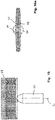
- FIG. 1 A first embodiment of the inventive applicator system is shown by Figures 1 to 4 . Particular reference is made to Figure 1 .
- the body 2 forming the reservoir(s) is embodied as a combination of a plunger 3 and a syringe 4.
- the interplay of the plunger 3 and the syringe 4 embodies two reservoirs 5 and 6.
- Each of the reservoirs 5, 6 contains one substance to be applied.
- the substances stored apart from one another are different in regard to their colour or their chemical and/or physical composition.
- the plunger 3 and the syringe 4 may be equipped with a protruding stopper 10 and 11.
- the stoppers 10, 11 improve the finger gripping when pressing the plunger 3 and the syringe 4 together in order to expel the substances out of their reservoirs 5, 6.
- the syringe 4 is equipped with a guiding tube 7, as shown by Fig. 3 .
- Said guiding tube 7 interacts with an according guiding tube 8 of the plunger 3. That way the guiding properties of the plunger 3 are improved.
- the syringe 4 forms a housing section HS with a valve seat 12.
- the valve seat 12 accommodates, preferably in a rotatable fashion, the valve body 13.
- valve body is positioned directly upstream of the applicator 15, without any additional duct that is formed outside of the valve body and that interconnects the valve body 13 and the applicator 15. Instead, the applicator is directly stuck into or onto the valve body 13.
- valve seat 12 The details of this valve seat 12 and the valve body 13 are shown by Fig. 4 .
- the valve body 13 forms a coupling portion 14.
- the coupling portion 14 can be designed that way that the applicator 15 can be coupled to the valve body 13 so that it is firmly hold by the valve body 13 even under the influence of the forces of the application.
- the applicator 15 is fixed to the valve body 13 by means of an elastic form fit connection.
- a form fit connection is realised as a snap-in connection.
- a coupling portion 14 alone is not responsible for holding the applicator 15 sufficiently firm.
- a snap-on cap 22 is provided.
- the snap-on cap 22 has a central hole that holds the applicator 15. This holding of the applicator is realized by means of the form fit between the borders confining the central hole of the snap-on cap and an annular groove 23 provided in the (shaft of the) applicator 15. As one sees the borders extend into an annular groove 23 in the applicator 15.
- FIG. 13 to 15 A more detailed view how the producing and loosing of said form fit can take place is depicted by Figs. 13 to 15 .
- the following design is advantageous:
- the applicator 15 can be stuck onto the coupling potion 14 of the valve body 13 by means of a straight movement along the longitudinal axis L, see the straight arrow.
- the applicator 15 is turned for substantially 90° (in clockwise direction here), as visualized by Fig. 14 .
- the valve body 13 remains stationary, it does not move during this locking process.
- the shaft of applicator 15 is not completely cylindrical but locally flattened, at least between the feed-in opening of the applicator 15 and the area for interaction with the snap-on cap 22.
- Said area, designed for accomplishing a form fit (positive interlocking fit) interaction of the applicator 15 with the snap-on cap 22 is positioned above the valve body 13.
- the snap-on cap 22 is designed that way that it can securely be snapped onto a complementary portion of the syringe 4 or, more exactly, onto a complementary portion of the housing HS formed by the syringe, as shown by Figure 4 .
- the snap-on cap 22 may have hooks 45 that snap into recesses or windows 46 of said housing HS as soon as the snap-on cap 22 has reached its final position, see what is shown by Fig. 4 and Fig. 1 . Moreover, the snap-on cap 22 secures the valve body 13 against extraction out of the valve seat 12.
- the interconnection between the valve body 13 and the applicator 15 is fluid tight.
- said tightness can be provided by the annular extension 25 of the applicator 15. Said annular extension 25 is stuck over the cylindrical flange CF of the valve body 13.
- valve body 13 even forms an annular groove so that the annular extension 25 of the applicator 15 is caught with its outer jacket JA as well as with its inner jacket. If a proper dimensioning and layout is provided, the interconnection can be designed that way that the annular extension 25 undergoes an elastic compression when being stuck over the cylindrical flange 26.
- the detaching of the applicator 15 shown is possible with the bare hands of the user, without using any tool, regardless whether a snap-on cap 22 is used or not.
- the interconnection that is formed between the valve body 13 of the applicator 15 allows itself the transfer of torque. That way the valve body 13 can be rotated by rotating the applicator 15.
- An optimized technical design provides that such a torque proof interconnection is realized by means of at least one protrusion or at least one tooth extending from the valve body 13 and gripping into a complementary recess of the applicator 15, or vice versa. Such a construction provides for positive locking fit in the direction of rotation.
- valve body 13 is equipped with two fully internal ducts 16 and 17.
- said ducts 16, 17 extend from the jacket portion of the valve body 13 into the interior of the valve body 13.
- the said jacket portion of the valve body 13 has preferably a conical shape. That way it is easier to grant tightness without burdensome narrowing of the tolerances, and to perform a very compact change of direction of the duct formed that way.
- said ducts 16 and 17 preferably meet a central output duct 18.
- This central output channel 18 is embodied along the rotational axis L of the valve body 13. In most cases said ducts 16 and 17 extend orthogonally to the rotational axis L of the valve body 13.
- the central output channel 18 is in fluidal connection with the duct 19 embodied in the applicator 15, more particular, embodied fully in the interior of the applicator 15.
- each pressure onto the plunger 3 expels the substances to be applied out of the reservoirs 5, 6.
- the substances flow through their ducts 20 and 21 in the syringe and enter through according mouth openings into the ducts 16 and 17 of the valve body 13. After having passed the ducts 16 and 17 of the valve body 13, the substances are fed into the central output channel 18 of the valve body 13. Nevertheless it is preferred that the two substances do not yet meet or mix here, for that purpose the central output chancel 18 provides two parallel but fully separated ducts.
- the substances flow into the duct 19 embodied in the applicator 15.
- the two substances are still kept apart for some distance within the duct 19. That way they will meet for first time when they arrive directly at the static mixer embodied within the applicator 15.
- the substances to be applied leave the internal area of the applicator system through the at least one mouth 27 of the applicator 15.
- the central output channel 18 has, as already described, in most cases two different tracks or ducts, too, that do not stand in any fluidal communication with one another. The reason for this is that it is in most cases not allowed that the different substances to be applied mix with one another before they have reached the applicator. Each mixing with one another would start a chemical reaction that has to be started completely out of the reusable parts of the applicator system in order to avoid clogging or detrimental effects in regard to the rest of the stored substances.
- a very interesting optional point is that even the duct 19 within the applicator 15 is designed that way that it forms in its beginning for some millimeters an entrance with two completely different and separated tracks that keep the at least two substances to be applied separated within the applicator until they enter into the static mixer within the applicator.
- the valve body 13 is rotatably hold by the valve seat 12, so that the valve body 13 can be rotated around the axis L by means of rotating the applicator 15. As soon as the valve body 13 is turned for example 90°, the situation is as shown by Figure 2 . That means the internal ducts 16 and 17 of the valve body 13 are not any longer in fluidal communication with the ducts 20 and 21 in the syringe 4 or - more generally spoken - in the body forming the reservoir. Instead, the valve body 13 blocks or seals the ducts 20 and 21, so that it is not possible to expel substances from the reservoir or reservoirs 5, 6.
- valve and/or the valve seat realize at least one rotation stopper where the rotation of the valve body 13 comes to an end as soon as the valve body is in its position where the ducts fully opened
- the duct 19 embodied in the applicator 15 is equipped with a static mixer 24 that mixes the substances expelled into the interior of the applicator during their flow along the interior of the applicator.
- the static mixer normally consists of a number of stationary hurdles that deflect the stream of the different substances repeatedly, back and forth, so that the local direction of flow changes. That leads to a mixing of the jointly flowing substances.
- the static mixer as such can be of one of the types as disclosed by prior published, granted patents EP 0730913 or EP 0885651 .
- the designs of the mixers as such and their physical embodiment and their fixation within or integration into an outer guiding tube is included into this application be reference.
- Fig. 4 Another optional detail is shown by Fig. 4 .
- the duct 19 embodied in the applicator 15 branches after completion of the mixing so that the mixed substances are locally dispensed trough several mouths 27 of the applicator at a number of places between the bristles or teeth of the applicator. That way a more uniform loading of the applicator with the substances to be applied is made sure.
- the second embodiment is very similar to the first embodiment so that all things described above for the first embodiment apply to the second embodiment, too, as long as nothing different is notified in the following.
- the body which serves as a reservoir.
- the body is constructed as a pump whose piston is driven by means of a screw driving mechanism.
- the main body portion 29 forms two reservoirs 5 and 6, too.
- the main body portion 29 holds a threaded spindle 30 within each reservoir 5 and 6.
- Each threaded spindle 30 carries a piston 31 that rides with its female thread on the male thread of said spindle 30.
- At the distal end each spindle 30 carries a sprocket 32.
- the main body portion 29 bears at its distal end a tubular sleeve 34 with an internal toothing 35.
- This tubular sleeve 34 is rotatably hold by the main body portion 29.
- the tubular sleeve 34 preferably possesses a tubular extension 36 that is stuck into the central guiding tube 37 of the main body portion 29.
- the internal toothing 35 and the sprockets 32 engage. That way the sprockets 32 are rotated as soon as the user turns the tubular sleeve 34. As soon as the sprockets 32 rotate, the threaded spindle 30 screws the pistons 31 in direction to the proximal i. e. in direction toward the applicator, for example. That way the substance to be applied is expelled out of its reservoir 5 or 6.
- valve mechanism and the way how to fix the applicator, for example to the valve body 13, are fully the same as described above for the first embodiment.
- the third embodiment is very similar to the first and the second embodiment, too. For that reason, all things described above apply to the third embodiment, too, as long as nothing different is notified in the following.
- the main body portion 29 forms a kind of bottle, in the case here a twin bottle with two different reservoirs 5 and 6.
- Each of the bottles preferably carries a bottleneck that is not shown in detail here.
- a sucking tube 38 is sunk into each reservoir 5 and 6.
- a said soap pump 39 is fixed.
- the soap pumps 39 may have a threaded cap each with which each soap pump is screwed onto the bottleneck assigned to it.
- the yoke 40 embodies a valve seat 12 as it is known from the first and the second embodiment. In the same manner as in the first and the second embodiment, the valve seat 12 accommodates a valve body 13.
- the valve body 13 is designed as already described. In Figure 11 it is displayed in its open position. In this position of the valve body 13 there is a continuous, uninterrupted duct between each of the soap pumps and the internal duct 19 of the applicator 15 that ends into at least one mouth 27 of the applicator.
- valve body 13 it is possible to couple at least one and preferably different applicators to the valve body 13 in a manner that allows to turn the valve body 13 by turning the applicator. That way the valve body 13 can be brought into its closed position, as described before.
- the applicator 15 is preferably equipped with a static mixer 24 that thoroughly mixes the substances to be applied that are fed by means of their ducts into the central output channel 18 in order to be conveyed from there to the internal duct 19 of the applicator.
- the invention is very advantageous if only one and the same applicator is used as a one-way applicator being disposed after application.
- Figure 16 discloses an internally fed applicator in the shape of a frontal comb 47.
- a frontal comb 47 Preferably all or at least a number of its tines 48 have an internal duct for dispensing the product to be applied through an orifice 49 at the end of the respective tine 48.
- the shaft 50 of this applicator accommodates a mixer which is of the type as explained before. Moreover the shaft 50 is embodied preferably in a way that it is fit for coupling to the snap-on cap, for example, as explained before. The features allowing this coupling action are not depicted here.
- the applicators are preferably designed such, that the 2 different substances to be mixed enter into the shaft 50 without being mixed before so that the substances come for first time in contact when they directly reach the mixer.
- the tines 48 being equipped with the internal ducts show a concave outer end with one or better opposite two lateral openings - so that their orifice 49 is not obstructed when the outer end of the tine comes in contact with the skin or the hairs.
- tines 48 that are not provided with internal ducts show an outer end having a chisel-like shape. Such a design improves the combing effect.
- Figure 17 discloses another alternative applicator. Compared to the applicator according to figure 16 this applicator may exhibit the only difference that no tines 48 are provided but bristles, in the shape of a bristle covering 51. The single bristles are flexible and in most of the cases none of the bristles is internally fed. Instead, even if an internal feeding is provided, such an internal feeding is accomplished by means of orifices that open out into the area of the roots of the bristles.
- shaft 50 of this applicator may accommodate the mixer of the type explained before if any mixer is used.
- shaft 50 is designed preferably in a way that it is fit for coupling to the snap-on cap 22, as explained before, for example. This is not depicted here.
- Figure 18 discloses another alternative applicator.
- This applicator may carrying no tines 48 or bristles but a blank, plane, convex or - at least slightly - concave surface 52.
- Said surface 52 may be flocked. It is a surface for spreading and smearing cosmetics.
- This applicator can be internally fed, too. In other cases such an applicator has no internal feeding. It is mounted to the device and used after prior outputting of cosmetics to the skin or hairs.
- Applicator system 1 for applying at least one flowable substance, with a body 2 forming at least one reservoir 5; 6 for storing at least one substance to be applied, a pump device for expelling the at least one substance out of the reservoir 5; 6, and a duct system 16, 17, 18, 19, 20, 21 for feeding the at least one pumped substance from the reservoir 5; 6 out of the body through the applicator 15 to at least one mouth 27 of the applicator 15, and a detachable applicator 15 for applying the at least one substance which is designed that way that the applicator system 1 comprises a movable valve 12, 13 that can be moved from an open to a closed position and vice versa by means of moving the applicator 15 relative to the body 2.
Abstract
Description
- The invention concerns an internally fed cosmetic or pharmaceutic applicator system for applying at least one flowable substance to a portion of the body or keratine fibers to be treated according to the preamble of
claim 1. - Internally fed applicator systems are known in different constellations.
- Most internal fed applicator systems offer one single applicator for applying the substance to the target area. Rather often the use of only one single applicator for one application job is disadvantageous since it is difficult to properly cover the different demands of application. For example if the applicator is rather big, it is easy to apply on rather huge surfaces while the precise drawing of a borderline may be difficult.
- Additional problems occur with such systems as soon as the storage container stores more than one single portion of the substance to be applied so that the applicator system is used only from time to time with long pauses in between. In this case the known applicator systems suffer from the drawback that the internally feeding ducts and the mixing portion run the risk to clog during the long pause between one and the next application. The risk of clogging increases if the applicator systems are stored between one and the next application while the applicator is detached and disposed or (in some cases) cleaned.
- According to a second aspect is an object of the invention to provide an internally fed applicator system that allows a more effective application even under very different application conditions.
- The inventive solution proposed to that end is an internally fed applicator system according to
claim 1. - Proposed is an cosmetic or pharmaceutic applicator system for applying at least one flowable substance to the body, skin or keratine fibers respectively hairs, preferably in the shape of a fluidal or viscous substance on the basis of water, alcohol, oil, fat, wax and/or silicone. This is a substance to be applied. The applicator system comprises a body forming different reservoirs for storing at least two substances to be applied. Moreover, it comprises a pump device for expelling the at least two substances out of the reservoirs. Finally it comprises a duct system for feeding the at least two pumped substances from the reservoir out of the body through the applicator to at least one outputting mouth of an applicator.
- It is a characteristic of the inventive solution that the applicator system comprises at least two different applicators. At least one of the applicators - and preferred all thereof - possess an internal static mixer. The applicators can be coupled according to the discretion of the user to the duct system in order to be internally fed with the at least two substances that way, that the at least two substances uniformly mix. It is highly preferred to give the ducts a design that ensures that a mixing takes place within the applicators only.
- Mostly the applicators are disposable. Preferably that means that the applicators are made of plastic material by injection moulding. Ideally the applicators are made of not more than two parts that are mounted to each other after having been moulded. Said parts are the applicator body itself (flocked or unflocked) and the static mixer pressed and/or clicked into it.
- That way it is possible to apply very conveniently, quickly and precisely. For large-area application namely for mass distribution and/or priming a big applicator with a huge application surface and maybe a high mass buffering capacity is used. For drawing fine lines afterwards an accordingly fine applicator is used. The reservoir with the cosmetics serves as comfortable handle.
- Preferably the or each mixer is embodied fully in the disposable applicator. That way only the applicator (head) must be cleaned or disposed and replaced while the container with the rest of the mass can be stored. The container stays ready for use up to the next application cycle some time later without being endangered to clog.
- A preferred embodiment provides that the applicator system comprises a movable valve that can be moved from an open to a closed position and vice versa by means of moving the applicator relative to the body.
- Such a system is easy to operate and seals the ducts (at least those ducts that are not part of the disposable applicator or applicator head itself) of the system securely against the detrimental effect of the ambient air etc. and prevents clogging.
- In another preferred embodiment the valve comprises a valve seat and a valve body, whereas the valve body comprises a coupling for fixing the applicator. The coupling is preferably designed as an annular notch into which an annular extension of the applicator is stuck.
- This design has the advantage that the ducts can be shut off directly upstream of the applicator, so that the duct portion that is exposed to the detrimental effect of ambient air etc. even after closing the valve is extremely short.
- Preferably, the valve body has at least one internal duct that is movable
- from a first position in which its - at least one - internal duct interconnects the at least one duct coming from the reservoir with the duct through the applicator

- to a second position in which its body blocks the interconnection between the at least one duct coming from the reservoir and the duct through the applicator.

- A valve body that is designed that way works very reliably even if substances to be applied are very viscous.
- A preferred embodiment provides that the valve body has two separate internal ducts for conducting different substances to a central output duct. The central output duct is embodied in the valve body where said separate internal ducts meet without coming into any fluidal contact with one another, since the central output duct preferably embodies two parallel but separated tracks that do not stand in fluidal communication with one another.
- Such a design with a central output duct provides for a very good preparation of the substances for the mixing (without having had contact before) within the applicator by means of a static mixer integrated into the applicator. The substances are kept completely separate from one another within the valve body.
- Preferably, the valve body is rotatably borne by the valve seat. A rotationally operated valve provides for an excellent fail safeness even under difficult operation conditions and can easily control two or more different conducts for two or more substances to be mixed before the output to the application surface.
- Preferably a rotation control is provided, so that the valve body cannot be rotated back and forth for more than totally 130° and better not more than totally 120°. In most ideal cases said rotation is limited to 90°. The aforementioned values apply to applicator systems using two different substances to be mixed before output on the application surface. For applicator systems using more than two of such substances a value of less than 75° is the optimum. That way it is made sure that it is not possible to unwantedly introduce the first substance into the region of the second substances and vice versa. With other words: That way an unwanted mixing of the substances within the valve is avoided, even if the valve is not operated with outermost care.
- It is of a particular interest if the movable valve can be moved from an open to a closed position and vice versa by means of moving the applicator relative to the body. Such a design allows a convenient operation of the valve without any additional tool and without smudging one's fingers.
- Preferably, at least one internal duct of the valve body extends from the jacket of the valve body to the center of the valve body.
- It is a characteristic of the inventive solution that the applicator system comprises at least two different applicators. At least one of the applicators - and preferred all thereof - possess an internal static mixer. The applicators can be coupled according to the discretion of the user to the duct system in order to be internally fed with the at least two substances that way, that the at least two substances uniformly mix, but preferably only within the applicators and preferably not before they have reached the applicators.
- Mostly the applicators are disposable. Preferably that means that the applicators are made of plastic material by injection moulding. Ideally the applicators are made of not more than two parts that are mounted to each other after having been moulded. Said parts are the applicator body itself (flocked or unflocked) and the static mixer.
- Further design aspects for further improving the invention are disclosed by the rest of the sub claims.
- Further technical effects, advantages, and improvement options are disclosed by the following description of preferred embodiments on the basis of the figures.
-
-
Figure 1 shows another review to an applicator system according to 1st embodiment of the invention. -
Figure 2 shows a longitudinal section through the applicator system according tofigure 1 . -
Figure 3 shows a longitudinal section through the applicator system according tofigure 1 , but turned for 90°. -
Figure 4 shows an enlarged view onto the housing and applicator portion of the applicator system shown byfigure 3 . -
Figure 5 shows a longitudinal section through the 2nd embodiment of the applicator system. -
Figure 6 shows an enlarged view onto the housing and applicator portion of the applicator system shown byfigure 5 . -
Figure 7 shows a front view to 3rd embodiment of an inventive an applicator system: -
Figure 8 shows a perspective view of the backside of the applicator system according tofigure 7 . -
Figure 9 shows a view from above to the applicator system according tofigure 7 . -
Figure 10 shows a longitudinal intersection through an applicator system according tofigure 7 . -
Figure 11 shows a horizontal intersection through the yoke of an applicator system according tofigure 7 . -
Figure 12 shows a vertical intersection (cutout) for the yoke of the applicator system according toFigure 7 . -
Figure 13 is the first picture of a sequence showing the possible form fit interaction between theapplicator 15 and the snap-oncap 22. -
Figure 14 is the second picture of a sequence showing the possible form fit interaction between theapplicator 15 and the snap-oncap 22. -
Figure 15 is the third picture of a sequence showing the possible form fit interaction between theapplicator 15 and the snap-oncap 22. -
Figure 16 shows another applicator to be used as a component of the inventive system. -
Fig. 16a shows a side view ofFig. 16 . -
Figure 17 shows another applicator to be used as a component of the inventive system. -
Fig. 17a shows a side view ofFig. 17 . -
Figure 18 shows another applicator to be used as a component of the inventive system. -
Fig. 18a shows a side view ofFig. 18 . - A first embodiment of the inventive applicator system is shown by
Figures 1 to 4 . Particular reference is made toFigure 1 . - Here, the
body 2 forming the reservoir(s) is embodied as a combination of aplunger 3 and a syringe 4. The interplay of theplunger 3 and the syringe 4 embodies tworeservoirs reservoirs - Preferably, the substances stored apart from one another are different in regard to their colour or their chemical and/or physical composition.
- The
plunger 3 and the syringe 4 may be equipped with a protrudingstopper stoppers plunger 3 and the syringe 4 together in order to expel the substances out of theirreservoirs - It is preferred that the syringe 4 is equipped with a guiding
tube 7, as shown byFig. 3 . Said guidingtube 7 interacts with an according guidingtube 8 of theplunger 3. That way the guiding properties of theplunger 3 are improved. - At its end - that is located opposite to the end with an opening 9 for introducing the plunger 3 - the syringe 4 forms a housing section HS with a
valve seat 12. Thevalve seat 12 accommodates, preferably in a rotatable fashion, thevalve body 13. - Preferably, the valve body is positioned directly upstream of the
applicator 15, without any additional duct that is formed outside of the valve body and that interconnects thevalve body 13 and theapplicator 15. Instead, the applicator is directly stuck into or onto thevalve body 13. - The details of this
valve seat 12 and thevalve body 13 are shown byFig. 4 . - The
valve body 13 forms acoupling portion 14. Thecoupling portion 14 can be designed that way that theapplicator 15 can be coupled to thevalve body 13 so that it is firmly hold by thevalve body 13 even under the influence of the forces of the application. - In most cases the
applicator 15 is fixed to thevalve body 13 by means of an elastic form fit connection. Normally, such a form fit connection is realised as a snap-in connection. - In the specific case shown here by
Fig. 4 , acoupling portion 14 alone is not responsible for holding theapplicator 15 sufficiently firm. - For reason of supporting the
coupling portion 14 embodied in thevalve body 13, a snap-oncap 22 is provided. The snap-oncap 22 has a central hole that holds theapplicator 15. This holding of the applicator is realized by means of the form fit between the borders confining the central hole of the snap-on cap and anannular groove 23 provided in the (shaft of the)applicator 15. As one sees the borders extend into anannular groove 23 in theapplicator 15. - A more detailed view how the producing and loosing of said form fit can take place is depicted by
Figs. 13 to 15 . The following design is advantageous:
Theapplicator 15 can be stuck onto thecoupling potion 14 of thevalve body 13 by means of a straight movement along the longitudinal axis L, see the straight arrow. Hereinafter theapplicator 15 is turned for substantially 90° (in clockwise direction here), as visualized byFig. 14 . Thevalve body 13 remains stationary, it does not move during this locking process. - Grace to this turning the (local) left-hand sided and righthand sided
annular grooves 23 become engaged with the borders confining the central hole of the snap-oncap 22, see what is visualized byFig. 15 . - As a summary one can say that it is a preferred embodiment if the shaft of
applicator 15 is not completely cylindrical but locally flattened, at least between the feed-in opening of theapplicator 15 and the area for interaction with the snap-oncap 22. Said area, designed for accomplishing a form fit (positive interlocking fit) interaction of theapplicator 15 with the snap-oncap 22 is positioned above thevalve body 13. - The snap-on
cap 22 is designed that way that it can securely be snapped onto a complementary portion of the syringe 4 or, more exactly, onto a complementary portion of the housing HS formed by the syringe, as shown byFigure 4 . - For that purpose, the snap-on
cap 22 may havehooks 45 that snap into recesses orwindows 46 of said housing HS as soon as the snap-oncap 22 has reached its final position, see what is shown byFig. 4 andFig. 1 . Moreover, the snap-oncap 22 secures thevalve body 13 against extraction out of thevalve seat 12. - Regardless how the snap-in connection between the
applicator 15 and thevalve body 13 is realized, it is in each case preferred that the interconnection between thevalve body 13 and theapplicator 15 is fluid tight. In case of the construction shown byFig. 4 , said tightness can be provided by theannular extension 25 of theapplicator 15. Saidannular extension 25 is stuck over the cylindrical flange CF of thevalve body 13. - More preferably, the
valve body 13 even forms an annular groove so that theannular extension 25 of theapplicator 15 is caught with its outer jacket JA as well as with its inner jacket. If a proper dimensioning and layout is provided, the interconnection can be designed that way that theannular extension 25 undergoes an elastic compression when being stuck over thecylindrical flange 26. - Preferably, the detaching of the
applicator 15 shown is possible with the bare hands of the user, without using any tool, regardless whether a snap-oncap 22 is used or not. - It is preferred that the interconnection that is formed between the
valve body 13 of theapplicator 15 allows itself the transfer of torque. That way thevalve body 13 can be rotated by rotating theapplicator 15. An optimized technical design provides that such a torque proof interconnection is realized by means of at least one protrusion or at least one tooth extending from thevalve body 13 and gripping into a complementary recess of theapplicator 15, or vice versa. Such a construction provides for positive locking fit in the direction of rotation. - As can be seen from
Fig. 4 , thevalve body 13 is equipped with two fullyinternal ducts - Preferably, said
ducts valve body 13 into the interior of thevalve body 13. - The said jacket portion of the
valve body 13 has preferably a conical shape. That way it is easier to grant tightness without burdensome narrowing of the tolerances, and to perform a very compact change of direction of the duct formed that way. - In the center of the
valve body 13 saidducts central output duct 18. Thiscentral output channel 18 is embodied along the rotational axis L of thevalve body 13. In most cases saidducts valve body 13. - The
central output channel 18 is in fluidal connection with theduct 19 embodied in theapplicator 15, more particular, embodied fully in the interior of theapplicator 15. - When the
valve body 13 takes the position shown byFig. 4 , the mouth of saidducts 16 and 17 - which are embodied in the jacket portion of the valve body 13 - communicate with theducts - That means that each pressure onto the
plunger 3 expels the substances to be applied out of thereservoirs ducts ducts valve body 13. After having passed theducts valve body 13, the substances are fed into thecentral output channel 18 of thevalve body 13. Nevertheless it is preferred that the two substances do not yet meet or mix here, for that purpose thecentral output chancel 18 provides two parallel but fully separated ducts. - Hereinafter the substances flow into the
duct 19 embodied in theapplicator 15. In most cases the two substances are still kept apart for some distance within theduct 19. That way they will meet for first time when they arrive directly at the static mixer embodied within theapplicator 15.
Finally, after being mixed, the substances to be applied leave the internal area of the applicator system through the at least onemouth 27 of theapplicator 15. - The
central output channel 18 has, as already described, in most cases two different tracks or ducts, too, that do not stand in any fluidal communication with one another. The reason for this is that it is in most cases not allowed that the different substances to be applied mix with one another before they have reached the applicator. Each mixing with one another would start a chemical reaction that has to be started completely out of the reusable parts of the applicator system in order to avoid clogging or detrimental effects in regard to the rest of the stored substances. - For that reason the mixer is completely integrated into the disposable applicators.
- A very interesting optional point is that even the
duct 19 within theapplicator 15 is designed that way that it forms in its beginning for some millimeters an entrance with two completely different and separated tracks that keep the at least two substances to be applied separated within the applicator until they enter into the static mixer within the applicator. - The reason for this is rather simple: That way it is made sure that the disposable applicator can be pulled off from the
valve body 13 without smudging thevalve body 13 unintendedly with a mixture of the two or more substances to be applied, that could start to harden within the valve 13 - so that thevalve 13 is clogged when some time later the next application will be started. - The
valve body 13 is rotatably hold by thevalve seat 12, so that thevalve body 13 can be rotated around the axis L by means of rotating theapplicator 15. As soon as thevalve body 13 is turned for example 90°, the situation is as shown byFigure 2 . That means theinternal ducts valve body 13 are not any longer in fluidal communication with theducts valve body 13 blocks or seals theducts reservoirs - Ideally, the valve and/or the valve seat realize at least one rotation stopper where the rotation of the
valve body 13 comes to an end as soon as the valve body is in its position where the ducts fully opened - It is very preferred that the
duct 19 embodied in theapplicator 15 is equipped with astatic mixer 24 that mixes the substances expelled into the interior of the applicator during their flow along the interior of the applicator. The static mixer normally consists of a number of stationary hurdles that deflect the stream of the different substances repeatedly, back and forth, so that the local direction of flow changes. That leads to a mixing of the jointly flowing substances. The static mixer as such can be of one of the types as disclosed by prior published, granted patentsEP 0730913 orEP 0885651 . The designs of the mixers as such and their physical embodiment and their fixation within or integration into an outer guiding tube is included into this application be reference. - Another optional detail is shown by
Fig. 4 . Theduct 19 embodied in theapplicator 15 branches after completion of the mixing so that the mixed substances are locally dispensed troughseveral mouths 27 of the applicator at a number of places between the bristles or teeth of the applicator. That way a more uniform loading of the applicator with the substances to be applied is made sure. - The second embodiment is very similar to the first embodiment so that all things described above for the first embodiment apply to the second embodiment, too, as long as nothing different is notified in the following.
- The difference is that for the second embodiment no combination of a classical combination of a syringe and a plunger is used in order to form the body which serves as a reservoir. Instead, the body is constructed as a pump whose piston is driven by means of a screw driving mechanism.
- The
main body portion 29 forms tworeservoirs - The
main body portion 29 holds a threadedspindle 30 within eachreservoir spindle 30 carries apiston 31 that rides with its female thread on the male thread of saidspindle 30. At the distal end eachspindle 30 carries asprocket 32. Moreover, themain body portion 29 bears at its distal end atubular sleeve 34 with aninternal toothing 35. Thistubular sleeve 34 is rotatably hold by themain body portion 29. For that purpose thetubular sleeve 34 preferably possesses atubular extension 36 that is stuck into thecentral guiding tube 37 of themain body portion 29. - The
internal toothing 35 and thesprockets 32 engage. That way thesprockets 32 are rotated as soon as the user turns thetubular sleeve 34. As soon as thesprockets 32 rotate, the threadedspindle 30 screws thepistons 31 in direction to the proximal i. e. in direction toward the applicator, for example. That way the substance to be applied is expelled out of itsreservoir - The valve mechanism and the way how to fix the applicator, for example to the
valve body 13, are fully the same as described above for the first embodiment. - The Figures for this embodiment illustrate that the
applicator system 1 can be easily equipped with adifferent applicator 15. In this particular case, that is not mandatory, the interlocking between the snap-oncap 22 and theapplicator 15 takes place as explained on the basis ofFigs. 4 to 16 - The third embodiment is very similar to the first and the second embodiment, too. For that reason, all things described above apply to the third embodiment, too, as long as nothing different is notified in the following.
- The difference is that for the third embodiment a piston pump is used in order to feed the substances to be applied via the
valve body 13 into theapplicator 15. For that reason, themain body portion 29 forms a kind of bottle, in the case here a twin bottle with twodifferent reservoirs tube 38 is sunk into eachreservoir soap pump 39 is fixed. For that purpose the soap pumps 39 may have a threaded cap each with which each soap pump is screwed onto the bottleneck assigned to it. - An interesting difference is the
yoke 40 that is stuck over the expellingtubes 41 of the soap pumps 39. That way the expellingtubes 41 of the soap pumps 39 feed the pumped substances into theyoke 40. For that purpose, theyoke 40 is equipped withinternal ducts yoke 40 embodies avalve seat 12 as it is known from the first and the second embodiment. In the same manner as in the first and the second embodiment, thevalve seat 12 accommodates avalve body 13. Thevalve body 13 is designed as already described. InFigure 11 it is displayed in its open position. In this position of thevalve body 13 there is a continuous, uninterrupted duct between each of the soap pumps and theinternal duct 19 of theapplicator 15 that ends into at least onemouth 27 of the applicator. - As already described, it is possible to couple at least one and preferably different applicators to the
valve body 13 in a manner that allows to turn thevalve body 13 by turning the applicator. That way thevalve body 13 can be brought into its closed position, as described before. - Again, the
applicator 15 is preferably equipped with astatic mixer 24 that thoroughly mixes the substances to be applied that are fed by means of their ducts into thecentral output channel 18 in order to be conveyed from there to theinternal duct 19 of the applicator. - In many cases the invention is very advantageous if only one and the same applicator is used as a one-way applicator being disposed after application.
- That way the stored contents keeps always fresh and in usable condition.
- Moreover a number of cases are conceivable in which the use of a number of different applicators is very helpful.
- For that purpose one or more of the applicators disclosed hereinafter can be used in addition.
-
Figure 16 discloses an internally fed applicator in the shape of a frontal comb 47. Preferably all or at least a number of itstines 48 have an internal duct for dispensing the product to be applied through an orifice 49 at the end of therespective tine 48. - The
shaft 50 of this applicator accommodates a mixer which is of the type as explained before. Moreover theshaft 50 is embodied preferably in a way that it is fit for coupling to the snap-on cap, for example, as explained before. The features allowing this coupling action are not depicted here. Once again the applicators are preferably designed such, that the 2 different substances to be mixed enter into theshaft 50 without being mixed before so that the substances come for first time in contact when they directly reach the mixer. - It is preferred that the
tines 48 being equipped with the internal ducts show a concave outer end with one or better opposite two lateral openings - so that their orifice 49 is not obstructed when the outer end of the tine comes in contact with the skin or the hairs. - Moreover it is preferred that those
tines 48 that are not provided with internal ducts show an outer end having a chisel-like shape. Such a design improves the combing effect. - It can be an option, to position directly alternating a
tine 48 with an internal duct and a tine with no internal duct as shown byFig. 16 . -
Figure 17 discloses another alternative applicator. Compared to the applicator according tofigure 16 this applicator may exhibit the only difference that notines 48 are provided but bristles, in the shape of a bristle covering 51. The single bristles are flexible and in most of the cases none of the bristles is internally fed. Instead, even if an internal feeding is provided, such an internal feeding is accomplished by means of orifices that open out into the area of the roots of the bristles. - Once again the
shaft 50 of this applicator may accommodate the mixer of the type explained before if any mixer is used. - Moreover the
shaft 50 is designed preferably in a way that it is fit for coupling to the snap-oncap 22, as explained before, for example. This is not depicted here. -
Figure 18 discloses another alternative applicator. This applicator may carrying notines 48 or bristles but a blank, plane, convex or - at least slightly -concave surface 52. Saidsurface 52 may be flocked. It is a surface for spreading and smearing cosmetics. - This applicator can be internally fed, too. In other cases such an applicator has no internal feeding. It is mounted to the device and used after prior outputting of cosmetics to the skin or hairs.
- Fully independent from the claims presented by now - or partially or fully merged with it - protection is claimed for the following:
Applicator system 1 for applying at least one flowable substance, with abody 2 forming at least onereservoir 5; 6 for storing at least one substance to be applied, a pump device for expelling the at least one substance out of thereservoir 5; 6, and aduct system reservoir 5; 6 out of the body through theapplicator 15 to at least onemouth 27 of theapplicator 15, and adetachable applicator 15 for applying the at least one substance which is designed that way that theapplicator system 1 comprises amovable valve applicator 15 relative to thebody 2. -
- 1
- applicator system
- 2
- body
- 3
- plunger
- 4
- syringe
- 5
- reservoir
- 6
- reservoir
- 7
- guiding tube syringe
- 8
- guiding tube plunger
- 9
- opening of syringe
- 10
- protruding stopper
- 11
- protruding stopper
- 12
- valve seat
- 13
- valve body
- 14
- coupling portion
- 15
- applicator
- 16
- duct of valve body
- 17
- duct of valve body
- 18
- central output channel
- 19
- duct embodied in the applicator
- 20
- duct within the syringe
- 21
- duct within the syringe
- 22
- snap-on cap
- 23
- annular groove
- 24
- static mixer
- 25
- annular extension
- 26
- cylindrical flange
- 27
- mouth of the applicator
- 28
- bristle or tooth or prong
- 29
- main body portion
- 30
- threaded spindle
- 31
- piston
- 32
- sprocket
- 34
- tubular sleeve
- 35
- internal toothing
- 36
- tubular extension
- 37
- central guiding tube
- 38
- sucking tube
- 39
- soap pump
- 40
- yoke
- 41
- expelling
tubes 41 - 42
- internal duct
- 43
- internal duct
- 44
- not awarded
- 45
- hook of the snap-on cap
- 46
- window for nesting the hook of the snap-on cap
- 47
- not assigned
- 48
- tine
- 49
- orifice
- 50
- shaft
- 51
- bristle covering
- 52
- blank application surface
- JA
- outer jacket
- CF
- cylindrical flange
- L
- longitudinal axis or axis of rotation
- HS
- housing section
Claims (15)
- Cosmetic or pharmaceutic applicator system (1) for applying at least two flowable substances preferably, whereas the applicator system (1) has a body (2) forming at least two reservoirs (5; 6) for storing at least two substances to be applied, a pump device for expelling the at least two substances out of the reservoirs (5; 6), and a duct system (16, 17, 18, 19, 20, 21) for feeding the at least two pumped substances from the reservoir (5; 6) out of the body (2) through the applicator (15) to at least one outputting mouth (27) of an applicator (15), characterized in that the applicator system (1) comprises at least two different applicators (15) - that may all possess an internal static mixer (24) - which can be coupled according to the discretion of the user to the duct system (16, 17, 18, 20, 21) in order to be internally fed with the at least two substances that way, that the at least two substances uniformly mix within the applicators (15).
- Applicator system (1) according to claim 1, characterized in that one of the applicators (15) carries bristles or prongs (28) and has a multiplicity of outputting mouths (27) that dispense the mixture of the substances to be applied between the bristles or prongs 20).
- Applicator system (1) according to one of the preceeding claims characterized in that at least one of the applicators (15) carries a flocking.
- Applicator system (1) according to one of the preceding claims characterized in that at least one of the applicators (15) carries a bare smudging surface without bristles, prongs, fingers, or carries a flocking.
- Applicator system (1) according to one of the preceding claims characterized in that at least one of the applicators (15) is a smearing or spreading applicator only and no internally fed applicator with a passage for substance to be applied passing through the applicator while at least one another alternative applicator is internally fed.
- Cosmetic or pharmaceutic applicator system according to one of the preceding claims for applying at least one flowable substance to the body or keratine fibers, with an applicator body (2) forming at least one reservoir (5; 6) for storing at least one substance to be applied, a pump device for expelling the at least one substance out of the reservoir (5; 6), and a duct system (16, 17, 18, 19, 20, 21) for feeding the at least one pumped substance from the reservoir (5; 6) out of the body through the applicator (15) to at least one mouth (27) of the applicator (15), and a detachable applicator (15) for applying the at least one substance characterized in that the applicator system (1) comprises a movable valve (12, 13) that can be moved from an open to a closed position and vice versa by means of moving the applicator (15) relative to the body (2).
- Applicator system (1) according to claim 6, characterized in that the valve (12, 13) comprises a valve seat (12) and a valve body (13), characterized in that the valve body (13) comprises a coupling portion (14) for fixing the applicator (15), whereas the coupling portion (14) is preferably designed as an annular notch into which an annular extension (25) of the applicator (15) is stuck.
- Applicator system (1) according to claim 6 or 7, characterized in that the valve body (13) has at least one internal duct (16; 17) and that the valve body (13) is movable from a first position in which its at least one internal duct (16; 17) interconnects the at least one duct (20, 21) coming from the reservoir (5; 6) with the duct (19) through the applicator (15) to a second position in which the valve body (13) blocks the interconnection between the at least one duct (20, 21) coming from the reservoir (5; 6) and the duct (19)through the applicator (15) .
- Applicator system (1) according to one of claims 6 to 8, characterized in that the valve body (13) has two separate internal ducts (16, 17) for conducting different substances to a central output channel (18) embodied in the valve body (13) where said separate internal (16, 17) ducts meet.
- Applicator system (1) according to one of to one of claims 6 to 9, characterized in that the valve body (13) is rotatably borne by the valve seat (12).
- Applicator system (1) according to one of claims 6 to 10, characterized in that a movable valve (12, 13) can be moved from an open to a closed position and vice versa by means of moving the applicator (15) relative to the body (2)
- Applicator system (1) according to one of claims 6 to 11, characterized in that at least one internal duct (16; 17) of the valve body (13) extends from the jacket of the valve body (13) to the center of the valve body (13).
- Applicator system (1) according to one of claims 6 to 12, characterized in that the jacket of the valve body (13) has a conical shape where the ducts (16, 17) start, that extend from the jacket of the valve body (13) to the center of the valve body (13).
- Applicator system (1) according to one of claims 6 to 13, characterized in that the longitudinal axes (L) of the ducts (20, 21) form a preferably right angle with the longitudinal axes (L) of the ducts (16, 17) of the valve body.
- Applicator system (1) according to one of to one of claims 6 to 14, characterized in that the valve seat (12) is embodied in a yoke (40) that interconnects the expelling tubes (41) of two or more pumps (39) that feed the pumped substances into the yoke (40) if the yoke (40) is pressed down, so that the expelling tubes (41) feed the internal ducts of the yoke (40), which, in turn, feed the internal ducts (16, 17) of the valve body (13) when it is in open position.
Priority Applications (2)
| Application Number | Priority Date | Filing Date | Title |
|---|---|---|---|
| EP18213658.0A EP3669697A1 (en) | 2018-12-18 | 2018-12-18 | Sealable internally fed applicator system |
| PCT/EP2019/086093 WO2020127583A1 (en) | 2018-12-18 | 2019-12-18 | Sealable internally fed applicator system |
Applications Claiming Priority (1)
| Application Number | Priority Date | Filing Date | Title |
|---|---|---|---|
| EP18213658.0A EP3669697A1 (en) | 2018-12-18 | 2018-12-18 | Sealable internally fed applicator system |
Publications (1)
| Publication Number | Publication Date |
|---|---|
| EP3669697A1 true EP3669697A1 (en) | 2020-06-24 |
Family
ID=64745954
Family Applications (1)
| Application Number | Title | Priority Date | Filing Date |
|---|---|---|---|
| EP18213658.0A Withdrawn EP3669697A1 (en) | 2018-12-18 | 2018-12-18 | Sealable internally fed applicator system |
Country Status (2)
| Country | Link |
|---|---|
| EP (1) | EP3669697A1 (en) |
| WO (1) | WO2020127583A1 (en) |
Citations (7)
| Publication number | Priority date | Publication date | Assignee | Title |
|---|---|---|---|---|
| US2446398A (en) * | 1946-09-21 | 1948-08-03 | Charley S Wilson | Handy comb |
| EP0305823A1 (en) * | 1987-08-29 | 1989-03-08 | Henkel Kommanditgesellschaft auf Aktien | Distribution device for multicomponent hair cosmetics, especially hair dyes |
| EP0730913A1 (en) | 1995-03-07 | 1996-09-11 | Wilhelm A. Keller | Bayonet fastening device for the attachment of an accessory to a multiple component cartridge or dispensing device |
| EP0885651A1 (en) | 1997-06-18 | 1998-12-23 | Wilhelm A. Keller | Mixer |
| EP1201318A1 (en) * | 2000-10-20 | 2002-05-02 | L'oreal | Dispensing assembly for the simultaneous distribution of two products |
| WO2003094657A1 (en) * | 2002-03-21 | 2003-11-20 | Sung Il Kang | Hairdyeing apparatus |
| DE202006011101U1 (en) * | 2006-07-18 | 2007-12-06 | Schwan-Stabilo Cosmetics Gmbh & Co. Kg | donor |
-
2018
- 2018-12-18 EP EP18213658.0A patent/EP3669697A1/en not_active Withdrawn
-
2019
- 2019-12-18 WO PCT/EP2019/086093 patent/WO2020127583A1/en active Application Filing
Patent Citations (7)
| Publication number | Priority date | Publication date | Assignee | Title |
|---|---|---|---|---|
| US2446398A (en) * | 1946-09-21 | 1948-08-03 | Charley S Wilson | Handy comb |
| EP0305823A1 (en) * | 1987-08-29 | 1989-03-08 | Henkel Kommanditgesellschaft auf Aktien | Distribution device for multicomponent hair cosmetics, especially hair dyes |
| EP0730913A1 (en) | 1995-03-07 | 1996-09-11 | Wilhelm A. Keller | Bayonet fastening device for the attachment of an accessory to a multiple component cartridge or dispensing device |
| EP0885651A1 (en) | 1997-06-18 | 1998-12-23 | Wilhelm A. Keller | Mixer |
| EP1201318A1 (en) * | 2000-10-20 | 2002-05-02 | L'oreal | Dispensing assembly for the simultaneous distribution of two products |
| WO2003094657A1 (en) * | 2002-03-21 | 2003-11-20 | Sung Il Kang | Hairdyeing apparatus |
| DE202006011101U1 (en) * | 2006-07-18 | 2007-12-06 | Schwan-Stabilo Cosmetics Gmbh & Co. Kg | donor |
Also Published As
| Publication number | Publication date |
|---|---|
| WO2020127583A1 (en) | 2020-06-25 |
Similar Documents
| Publication | Publication Date | Title |
|---|---|---|
| US8021064B2 (en) | Packaging and applicator device | |
| US5152305A (en) | Applicator device | |
| US7934512B2 (en) | Hair highlighting applicator | |
| US5913314A (en) | Combination salon tool device | |
| US6302607B1 (en) | Fluid applicators | |
| US6675812B1 (en) | Dispenser with comb or brush with optional sponge for cream, lotion, gel or liquid | |
| CN103607926B (en) | For hair products being applied to the device on a thread | |
| EP1032287B1 (en) | Fluid applicators | |
| US6244273B1 (en) | Water comb | |
| CN110996714B (en) | Device for dispensing and applying cosmetic or care products | |
| US6722804B2 (en) | Applique package and method of manufacture | |
| EP3669697A1 (en) | Sealable internally fed applicator system | |
| EP3669999B1 (en) | Sealable internally fed applicator system | |
| JP2008024339A (en) | Squeeze container | |
| US20130048003A1 (en) | Hair highlighting applicator comb | |
| JP2001523526A (en) | Fluid delivery system | |
| US20140311509A1 (en) | Disposable hair lightening applicator comb | |
| EP0264824B1 (en) | Dispenser for pastry products | |
| US20210227947A1 (en) | Liquid Hair Product Dispenser | |
| US9943153B2 (en) | Applicator and a dye kit comprising said applicator | |
| US20220386768A1 (en) | Cloud Comb | |
| CA3064204A1 (en) | Hair coloring variegation device and method of use | |
| JP4182513B2 (en) | Dispensing container | |
| US20220265020A1 (en) | Dispenser, comb, housing and method of using the dispenser | |
| US20090311034A1 (en) | Shearing assembly |
Legal Events
| Date | Code | Title | Description |
|---|---|---|---|
| PUAI | Public reference made under article 153(3) epc to a published international application that has entered the european phase |
Free format text: ORIGINAL CODE: 0009012 |
|
| STAA | Information on the status of an ep patent application or granted ep patent |
Free format text: STATUS: THE APPLICATION HAS BEEN PUBLISHED |
|
| AK | Designated contracting states |
Kind code of ref document: A1 Designated state(s): AL AT BE BG CH CY CZ DE DK EE ES FI FR GB GR HR HU IE IS IT LI LT LU LV MC MK MT NL NO PL PT RO RS SE SI SK SM TR |
|
| AX | Request for extension of the european patent |
Extension state: BA ME |
|
| STAA | Information on the status of an ep patent application or granted ep patent |
Free format text: STATUS: REQUEST FOR EXAMINATION WAS MADE |
|
| 17P | Request for examination filed |
Effective date: 20201216 |
|
| RBV | Designated contracting states (corrected) |
Designated state(s): AL AT BE BG CH CY CZ DE DK EE ES FI FR GB GR HR HU IE IS IT LI LT LU LV MC MK MT NL NO PL PT RO RS SE SI SK SM TR |
|
| STAA | Information on the status of an ep patent application or granted ep patent |
Free format text: STATUS: EXAMINATION IS IN PROGRESS |
|
| 17Q | First examination report despatched |
Effective date: 20221123 |
|
| STAA | Information on the status of an ep patent application or granted ep patent |
Free format text: STATUS: THE APPLICATION IS DEEMED TO BE WITHDRAWN |
|
| 18D | Application deemed to be withdrawn |
Effective date: 20230404 |