EP0444247A1 - Reverse flow dispensing mixer - Google Patents
Reverse flow dispensing mixer Download PDFInfo
- Publication number
- EP0444247A1 EP0444247A1 EP90121732A EP90121732A EP0444247A1 EP 0444247 A1 EP0444247 A1 EP 0444247A1 EP 90121732 A EP90121732 A EP 90121732A EP 90121732 A EP90121732 A EP 90121732A EP 0444247 A1 EP0444247 A1 EP 0444247A1
- Authority
- EP
- European Patent Office
- Prior art keywords
- dispensing
- mixing nozzle
- mixer
- shell
- tubular shell
- Prior art date
- Legal status (The legal status is an assumption and is not a legal conclusion. Google has not performed a legal analysis and makes no representation as to the accuracy of the status listed.)
- Ceased
Links
Images


Classifications
-
- B—PERFORMING OPERATIONS; TRANSPORTING
- B05—SPRAYING OR ATOMISING IN GENERAL; APPLYING FLUENT MATERIALS TO SURFACES, IN GENERAL
- B05C—APPARATUS FOR APPLYING FLUENT MATERIALS TO SURFACES, IN GENERAL
- B05C17/00—Hand tools or apparatus using hand held tools, for applying liquids or other fluent materials to, for spreading applied liquids or other fluent materials on, or for partially removing applied liquids or other fluent materials from, surfaces
- B05C17/005—Hand tools or apparatus using hand held tools, for applying liquids or other fluent materials to, for spreading applied liquids or other fluent materials on, or for partially removing applied liquids or other fluent materials from, surfaces for discharging material from a reservoir or container located in or on the hand tool through an outlet orifice by pressure without using surface contacting members like pads or brushes
- B05C17/00553—Hand tools or apparatus using hand held tools, for applying liquids or other fluent materials to, for spreading applied liquids or other fluent materials on, or for partially removing applied liquids or other fluent materials from, surfaces for discharging material from a reservoir or container located in or on the hand tool through an outlet orifice by pressure without using surface contacting members like pads or brushes with means allowing the stock of material to consist of at least two different components
-
- A—HUMAN NECESSITIES
- A61—MEDICAL OR VETERINARY SCIENCE; HYGIENE
- A61C—DENTISTRY; APPARATUS OR METHODS FOR ORAL OR DENTAL HYGIENE
- A61C5/00—Filling or capping teeth
- A61C5/60—Devices specially adapted for pressing or mixing capping or filling materials, e.g. amalgam presses
- A61C5/62—Applicators, e.g. syringes or guns
- A61C5/64—Applicators, e.g. syringes or guns for multi-component compositions
-
- B—PERFORMING OPERATIONS; TRANSPORTING
- B05—SPRAYING OR ATOMISING IN GENERAL; APPLYING FLUENT MATERIALS TO SURFACES, IN GENERAL
- B05C—APPARATUS FOR APPLYING FLUENT MATERIALS TO SURFACES, IN GENERAL
- B05C17/00—Hand tools or apparatus using hand held tools, for applying liquids or other fluent materials to, for spreading applied liquids or other fluent materials on, or for partially removing applied liquids or other fluent materials from, surfaces
- B05C17/005—Hand tools or apparatus using hand held tools, for applying liquids or other fluent materials to, for spreading applied liquids or other fluent materials on, or for partially removing applied liquids or other fluent materials from, surfaces for discharging material from a reservoir or container located in or on the hand tool through an outlet orifice by pressure without using surface contacting members like pads or brushes
- B05C17/01—Hand tools or apparatus using hand held tools, for applying liquids or other fluent materials to, for spreading applied liquids or other fluent materials on, or for partially removing applied liquids or other fluent materials from, surfaces for discharging material from a reservoir or container located in or on the hand tool through an outlet orifice by pressure without using surface contacting members like pads or brushes with manually mechanically or electrically actuated piston or the like
Definitions
- the present invention is directed to the field of multiple material mixing and dispensing, and more particularly to a dispensing mixer suited for use with a dispensing gun for intermixing and dispensing a composite of materials from a common nozzle.
- the mixing nozzle (30) is preferably in the symmetrical center of the tubular shell and includes slotted openings (41) and (42) adjacent the rear end (34) of the tubular shell (24), which communicate with the storage compartments (25) and (26) to provide for the egress of material from the compartments (25) and (26) upon the application of pressure to the head (40), of the piston assembly (36).
- the dispensing mixer (10) is ready to be inserted into the extrusion gun (12) of Figure 1 once the compartments (25) and (26) are loaded with a desired material, and the cap (22) rotated to align the slot (52) with the openings (41) and (42), as shown in Figure 7.
- Any material composition of any desired viscosity may be loaded into the compartments (25) and (26) of the tubular shell (24).
- Resin materials, which upon intermixing become active for use as an adhesive or as a dental filling material, are particularly well suited for use in the mixer (10). It should, however, be understood that any materials which require intermixing in situ immediately before use, particularly materials having a heavy consistency, may be used.
- a conventional-type caulking gun (60) may also be used to operate the dispensing mixer (10), as shown in Figure 10.
- the dispensing mixer (10) would be loaded into the open breach (62) of the caulking gun (60).
- the end face (66) of the gun (60) has a horseshoe-like-configuration which engages the head (40) of the piston assembly (36).
- a constricting force is developed between the head (40) and the closure cap (22) of the mixer (10), for discharging mixed effluent from the discharge spout (14), as explained heretofore in connection with Figure 1.
- the tubular shell (24) terminates in an end plate (70), which extends from a tubular neck (71) mounted over the common mixing nozzle (30) to seal off compartments (25) and (26), respectively.
- the end plate (70) lies in a plane substantially transverse to the longitudinal axis of the tubular shell (24), and has a diameter larger than the diameter of the tubular shell (24) to form an overhanging lip (72).
- the closure cap (22) has a complementary lip (74) which engages the lip (72) upon press fitting the cap (22) over the tubular shell (24).
- the cap (22) is rotated until the holes (84) and (85) register with the corresponding openings (41) and (42) in the mixing nozzle (30). In this position, the material stored in the storage compartments (25) and (26) may be discharged into the common mixing nozzle (30) upon actuation of the piston assembly (36), in response to the manual operation of the extrusion gun.
- a static mixing element (not shown) is inserted into the mixing nozzle (30).
- the closure cap (22) has a complementary lip (74) for engaging the lip (72) upon press fitting the cap (22) over the tubular shell (24).
- a slot (94) is formed in the tubular shell (24) of generally torus configuration.
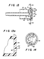
- the closure cap (22) can be rotated into an open position, as shown in Figures 13 and 14, or a closed position. In the open position, the slot (94) provides a passageway connecting the openings (92) and (93) to the common mixing nozzle (30). When the closure cap (22) is rotated ninety degrees into the closed position, the openings (92) and (93) are blocked off.
- Rotation of the cap (22) into an open or closed position is controlled by a curved slot (95) in the end wall (47) of the closure cap (22), and a stopping pin (96) extending from the end plate (70) into the curved slot (95).
- the stopping pin (96) allows the end cap (22) to be rotated into either the open or closed positions, respectively.
- the end plate (90) is preferably molded with a protruding shoulder (97) formed about the opening (92), and a corresponding protruding shoulder (98) formed about opening (93).
- the torus slot (94) forms an end (99) which abuts the end plate (90) to form a knife edge (100) and (103) respectively with edged (100) engaging the edge (102) of the shoulder (97) and the edge ( 103) engaging the corresponding edge of the shoulder (98).
- This arragement forms an annular seal at the interface with the end plate (90) to prevent leakage in the open position upon discharging material from the compartments (25) and (26), respectively.
Landscapes
- Health & Medical Sciences (AREA)
- Oral & Maxillofacial Surgery (AREA)
- Dentistry (AREA)
- Epidemiology (AREA)
- Life Sciences & Earth Sciences (AREA)
- Animal Behavior & Ethology (AREA)
- General Health & Medical Sciences (AREA)
- Public Health (AREA)
- Veterinary Medicine (AREA)
- Engineering & Computer Science (AREA)
- Mechanical Engineering (AREA)
- Coating Apparatus (AREA)
- Containers And Packaging Bodies Having A Special Means To Remove Contents (AREA)
Abstract
A dispensing mixer unit suited for use with a dispensing gun for mixing and dispensing at least two materials (25-26) through a common mixing nozzle. The dispensing mixer comprises a tubular shell (24) having at least two compartments for separately storing the materials to be intermixed and a common mixing nozzle (30), with the shell surrounding the common mixing nozzle in a concentric arrangement.
Description
- The present invention is directed to the field of multiple material mixing and dispensing, and more particularly to a dispensing mixer suited for use with a dispensing gun for intermixing and dispensing a composite of materials from a common nozzle.
- The art of mixing two components, stored separately in a double barrel syringe to form a single mixed product by forcing the components through a static mixing element located in a common discharge nozzle, is described in U.S. Patent No. 4,753,536, issued to Spehar, et al., on June 28, 1988. The discharge nozzle is removably coupled to the multiple barrel syringe containing the separately stored components to form an elongated dispenser, with the discharge nozzle and multiple barrel syringe axially aligned relative to one another so that the material discharged from the syringe flows along a linear path extending unidirectionally from the syringe through the discharge nozzle. The syringe is, in turn, adapted to be coupled to a pair of plungers from a dispensing gun which has movable pistons for forcing material from each of the barrels upon actuating the plungers. This results in a device which, by necessity, has a relatively long axial dimension, with the length of the syringe, the length of the discharge nozzle, and the length of the gun plunger assembly defining the overall length of the device.
- There exist many medical and commercial applications for dispensing a mixed composite product of two or more materials in a very limited working space. In such cases, the space limitation mandates a design configuration in which the length of the device, including the cartridge and mixer, is relatively short.
- The dispensing mixer of the present invention is suited for use with a dispensing gun and includes means for separately storing two or more materials in a tubular shell surrounding a common mixing nozzle in which a static mixing element is placed. In accordance with the design of the present invention, the stored materials are fed in one direction from their respective storage compartments into the common mixing nozzle with the direction of flow then reversed for passage through the mixing nozzle, thereby limiting the overall length of the dispenser. This arrangement condenses the overall length of the unit to less than about fifty percent of the length of the prior art type of dispenser as discussed heretofore.
- The dispensing device of the present invention is adapted for mixing and dispensing at least two materials through a common mixing nozzle and comprises:
a tubular shell surrounding said common mixing nozzle with the tubular shell having opposite ends and with said common mixing nozzle extending axially from one of said opposite ends;
partition means located in said shell for dividing said shell into at least two storage compartments for separately storing the materials to be intermixed and dispensed from said device;
piston means axially aligned with said tubular shell and extending from one of said opposite ends in juxtaposition with each of said storage compartments;
a static mixing element disposed in said common mixing nozzle; and
means for providing a controlled passageway from each storage compartment in said shell to said common mixing nozzle, such that upon relative advancement of said piston means into said storage compartments, the stored materials are forced to flow in one direction from each storage compartment through said controlled passageway into said common mixing nozzle with the direction of flow reversed through said common mixing nozzle. - Advantages of the present invention will become apparent from reading the following detailed description of the invention in conjunction with the accompanying drawings of which:
- Figure 1 is a side elevation of a dispensing gun loaded with the dispensing mixer of the present invention for discharging a mixed extruded composite product through a common nozzle;
- Figure 2 is a cross-sectional view through the center of the dispensing mixer shown partly in section and partly exploded;
- Figure 3 is an end view of the dispensing mixer of Figure 2 taken along the lines 3-3 in Figure 2;
- Figure 4 is an end view of the closure for the dispensing mixer shown in Figure 2 taken along the lines 4-4 of Figure 2;
- Figure 5 is a view in perspective of the dispensing mixer of Figure 2 illustrating how the closure is operatively attached to the shell of the dispensing mixer;
- Figure 6 is another perspective view, similar to Figure 5, viewed from the side opposite to that of Figure 5;
- Figure 7 is a view in longitudinal cross section of the dispensing mixer of Figure 2 shown in its fully extended position with the storage compartments shown completely filled and before operating the unit;
- Figure 8 is another view, similar to Figure 7, with the dispensing mixer of the present invention partially actuated so that storage material has begun to intermix through the mixing nozzle;
- Figure 9 is yet another view, similar to Figure 8, with the dispensing mixer of the present invention shown substantially fully discharged;
- Figure 10 shows the dispensing mixer of the present invention loaded into another type of conventional cartridge gun for dispensing a mixed extruded composite product.
- Figure 11 is a cross-sectional view of another embodiment of the dispensing mixer of the present invention shown partly in section and partly exploded;
- Figure 12 is similar to Figure 11, with the closure cap shown coupled to the tubular shell of the dispensing mixer;
- Figure 13 is a cross-sectional view of Yet another embodiment of a coupling arrangement between the closure cap and the tubular shell;
- Figure 13A is an exploded view of a section of the rear end of the tubular shell of Figure 13; and
- Figure 14 is an end view of the closure cap in Figure 13 taken along the lines 14-14 of Figure 13.
- Referring to the drawings, particularly Figure 1, in which the dispensing mixer (10) of the present invention is shown loaded into a manually-operated extrusion gun (12) for controllably discharging a mixed extruded composite product from a common discharge spout (14) in the dispensing mixer (10). The extrusion gun (12) is, of itself, a conventional extrusion device having a fixed handle (15) which is pistol-shaped and adapted to be gripped by the fingers of one hand, a movable lever (16) which is pivotally connected to the handle (15), and a plunger assembly (18) which engages the lever (16) for slidably moving the plunger (18) into a tubular barrel (19) in response to pressure applied between the handle (15) and the lever (16), preferably using the palm of the same hand holding the gun (12). The dispensing mixer (10) is loaded into the tubular barrel (19) by threadably removing the front tip (20) from the barrel (19). Alternatively, the barrel (19) may be designed with a front end having a semi-hemispherical geometry (not shown), in substitution for the front tip (20), with the dispensing mixer (10) forced fitted to tightly engage the barrel (19) at such front end. The plunger assembly (18) has a fitting (not shown) in contact with the closure cap (22) for the dispensing unit (10), as shown in Figures 2-6. In operation, the plunger (18) presses against the closure cap (22) of the dispensing mixer (10) upon squeezing together the handle (15) and the lever (16). This applies a contraction force between opposite ends of the dispensing mixer (10), which forces the materials stored in the dispensing mixer (10) through the discharge spout (14), as will be discussed hereafter at length.
- Referring now to Figures 2-9 inclusive, in which the dispensing mixer (10) of the present invention is shown comprising a tubular shell (24) divided into at least two compartments (25) and (26), separated by partition walls (27) and (28), respectively. The partition walls (27) and (28) need not divide the compartments (25) and (26) into equal sizes. The tubular shell (24) surrounds a common mixing nozzle (30) which is preferably of cylindrical geometry, but need not be centrally positioned in the tubular shell. The mixing nozzle (30) is tapered to form a common discharge spout (14). The closure cap (22) is fastened to the rear end (34) of the tubular shell (24) and is rotatable into an open or closed position, as will hereafter be discussed in detail. The compartments (25) and (26) in the tubular shell (24) may be loaded with materials through either opposite end of the tubular shell (24), although preferably from the front end (35) by withdrawing the piston assembly (36) and locking the closure cap (22) on the rear end (34).
- The piston assembly (36) includes a plurality of pistons (37) and (38), corresponding in number to the number of storage compartments in the shell (24). The pistons are mounted in sliding engagement over the mixing nozzle (30), with each piston (37) and (38) juxtaposed in registration, with a corresponding compartment (25) and (26) of the shell (24). The pistons (37) and (38) extend from a common head (40) and are of a geometry and size complementary to the geometry and size of the corresponding compartments (25) and (26) with which each is registered, so that upon applying force to the head (40), the pistons (37) and (38) are driven in common into the compartments (25) and (26), for urging the material contents from the compartments (25) and (26) toward the read end (34) of the tubular shell (24). The compartments (25) and (26) and the corresponding pistons need not be of matching size. Accordingly, any desired ratio may be achieved by using predesigned compartment geometry and volume ratios. The corresponding pistons must match the size of the compartments into which they feed. Thus, the pistons (37) and (38) will apply an equal force to each of the compartments (25) and (26), respectively.
- The mixing nozzle (30) is preferably in the symmetrical center of the tubular shell and includes slotted openings (41) and (42) adjacent the rear end (34) of the tubular shell (24), which communicate with the storage compartments (25) and (26) to provide for the egress of material from the compartments (25) and (26) upon the application of pressure to the head (40), of the piston assembly (36).
- The tubular shell (24) has an annular protrusion (45) which locks into an annular slot (44) in the closure cap (22) upon pressing the cap (22) over the rear end (34) of the shell (24). The closure cap (22) has an end wall (47) which abuts the rear end (34) of the tubular shell (24) when the cap (22) is fitted over the shell (24). The closure cap (22) also has a pair of curved walls (49) and (50) which extend from the end wall (47) and are complementary to one another. The curved walls (49) and (50) form sectors of a cylinder having a diameter slightly smaller than the diameter of the cylindrical conduit (30), so that when the cap (22) is fitted over the shell (24), the projections (49) and (50) fit within the cylindrical conduit (30) at the rear end (34) of the shell (24) to form a relatively tight fit. The curved walls (49) and (50) are spaced apart, forming a keyway (52), as shown in Figures 4 and 5. The alignment of keyway (52) with the openings (41) and (42) in the cylindrical conduit (30) is controlled by manual rotation of the cap (22). In the aligned position, the material from each compartment (25) and (26) will flow into the central mixing nozzle (30) upon applying force to the piston head (40). In the non-aligned position, the openings (41) and (42) are blocked.
- A static mixing element (54) (as shown only in Figures 7 and 8) is inserted into the hollow mixing nozzle (30) to permit common mixing of the materials in nozzle (30). The interior wall of nozzle (30) may be slightly tapered (not shown) to permit the static mixing element (54) to fit snugly inside. The static mixing element (54) is a conventional device with a multiplicity of twisted, auger-like mixing blades. The number of mixing blades (51) controls how well the materials intermix to form a homogeneously mixed product within the nozzle (30).
- The dispensing mixer (10) is ready to be inserted into the extrusion gun (12) of Figure 1 once the compartments (25) and (26) are loaded with a desired material, and the cap (22) rotated to align the slot (52) with the openings (41) and (42), as shown in Figure 7. Any material composition of any desired viscosity may be loaded into the compartments (25) and (26) of the tubular shell (24). Resin materials, which upon intermixing become active for use as an adhesive or as a dental filling material, are particularly well suited for use in the mixer (10). It should, however, be understood that any materials which require intermixing in situ immediately before use, particularly materials having a heavy consistency, may be used. Figures 8 and 9 show the dispensing mixer in a partially discharged and a substantially fully discharged position, respectively. At any interim discharge position, the mixer (10) may be removed from the gun (12) and the cap (22) rotated to temporarily block further egress of material through the discharge nozzle (32). Once the materials are mixed, the dispensing mixer is reusable only upon removal and replacement of the static mixing element (54) before the mixed materials in the common mixing nozzle (30) gel.
- A conventional-type caulking gun (60) may also be used to operate the dispensing mixer (10), as shown in Figure 10. The dispensing mixer (10) would be loaded into the open breach (62) of the caulking gun (60). To receive the mixer (10), the end face (66) of the gun (60) has a horseshoe-like-configuration which engages the head (40) of the piston assembly (36). Upon actuating the conventional pawl and ratchet hand-control mechanism (68), a constricting force is developed between the head (40) and the closure cap (22) of the mixer (10), for discharging mixed effluent from the discharge spout (14), as explained heretofore in connection with Figure 1.
- Several alternative embodiments of the dispensing mixer (10) are shown in Figures 11-14, inclusive. In the configuration of Figures 11 and 12, the tubular shell (24) terminates in an end plate (70), which extends from a tubular neck (71) mounted over the common mixing nozzle (30) to seal off compartments (25) and (26), respectively. The end plate (70) lies in a plane substantially transverse to the longitudinal axis of the tubular shell (24), and has a diameter larger than the diameter of the tubular shell (24) to form an overhanging lip (72). The closure cap (22) has a complementary lip (74) which engages the lip (72) upon press fitting the cap (22) over the tubular shell (24). The closure cap (22) also has an annular slot (76) to receive the tubular neck (71) of the end plate (70). The annular slot (76) is formed between a cylindrical wall. (80) and a tubular extension (81), each of which extends from the end wall (47) of the closure cap (22). The tubular extension (81) has an annular groove (82), which receives a dimple (86) extending from the inside periphery of the neck (71), when the closure cap (22) is snapped over the tubular shell (24) to firmly lock the cap (22) in place. The tubular extension (81) has two openings (84) and (85), which permit material to flow into the mixing nozzle (30), when the holes (84) and (85) are aligned with openings (41) and (42). The cap (22) is rotated until the holes (84) and (85) register with the corresponding openings (41) and (42) in the mixing nozzle (30). In this position, the material stored in the storage compartments (25) and (26) may be discharged into the common mixing nozzle (30) upon actuation of the piston assembly (36), in response to the manual operation of the extrusion gun. A static mixing element (not shown) is inserted into the mixing nozzle (30).
- In the configuration of Figures 11 and 12, the piston assembly (36) has two hollow pistons (88) and (89), which are preferably composed of an inflexible resinous composition. Flexible tips (83) and (87) of an elastomeric composition having flared or flanged ends (90) and (91)are attached to the ends of corresponding pistons (88) and (89) to act as sealing wipers, to insure positive wiping of the walls of the compartments (25) and (26) during the piston stroke and to prevent back flow of material.
- Another variation of a coupling arrangement between the closure cap (22) and the tubular shell (24) is shown in Figures 13, 13A and 14, inclusive. In this arrangement, the tubular shell (24) terminates in end plate (90), extending from the mixing nozzle (30). In this configuration, the mixing nozzle does not have openings (41) and (42). Instead the end plate (90) has openings (92) and (93), with opening (92) contiguous to compartment (25) and opening (93) contiguous to compartment (26), respectively. The end plate (90) lies in a plane substantially transverse to the longitudinal axis of the tubular shell and is of a diameter larger than the diameter of the tubular shell to form an overhanging lip (72).
- The closure cap (22) has a complementary lip (74) for engaging the lip (72) upon press fitting the cap (22) over the tubular shell (24). A slot (94) is formed in the tubular shell (24) of generally torus configuration. The closure cap (22) can be rotated into an open position, as shown in Figures 13 and 14, or a closed position. In the open position, the slot (94) provides a passageway connecting the openings (92) and (93) to the common mixing nozzle (30). When the closure cap (22) is rotated ninety degrees into the closed position, the openings (92) and (93) are blocked off. Rotation of the cap (22) into an open or closed position is controlled by a curved slot (95) in the end wall (47) of the closure cap (22), and a stopping pin (96) extending from the end plate (70) into the curved slot (95). The stopping pin (96) allows the end cap (22) to be rotated into either the open or closed positions, respectively. The end plate (90) is preferably molded with a protruding shoulder (97) formed about the opening (92), and a corresponding protruding shoulder (98) formed about opening (93). The torus slot (94) forms an end (99) which abuts the end plate (90) to form a knife edge (100) and (103) respectively with edged (100) engaging the edge (102) of the shoulder (97) and the edge ( 103) engaging the corresponding edge of the shoulder (98). This arragement forms an annular seal at the interface with the end plate (90) to prevent leakage in the open position upon discharging material from the compartments (25) and (26), respectively.
Claims (6)
- A dispensing mixer for intermixing and dispensing at least two materials through a common mixing nozzle comprising:
a tubular shell surrounding said common mixing nozzle with said tubular shell having opposite ends and with said nozzle extending axially from one of said opposite ends;
partition means located in said shell for dividing said shell into at least two storage compartments for separately storing the materials to be intermixed and dispensed from said device;
piston means axially aligned with said tubular shell and extending from one of said opposite ends in juxtaposition with each of said storage compartments;
a static mixing element disposed in said common mixing nozzle; and
means for providing a controlled passageway from each storage compartment in said shell to said common mixing nozzle, such that upon relative advancement of said piston means into storage compartments, the stored materials are forced to flow in one direction from each storage compartment through said controlled passageway into said common mixing nozzle with the direction of flow reversed through said common mixing nozzle. - A dispensing mixer, as defined in claim 1, wherein said means for providing a controlled passageway comprises an opening in said mixing nozzle for communicating with each compartment.
- A dispensing mixer, as defined in claim 2, further comprising closure means for sealing the end of said tubular shell opposite said piston means.
- A dispensing mixer, as defined in claim 3, wherein said closure means further comprises control means for opening said controlled passageway in one position of said closure means and for blocking said controlled passageway in another position.
- A dispensing mixer, as defined in claim 4, wherein said closure means includes a keyway for opening or closing said controlled passageway upon manual rotation of said closure means.
- A dispensing mixer, as defined in claim 2, wherein said piston means comprises a piston head and a fixed number of pistons extending from the head, corresponding to the number of storage compartments.
Applications Claiming Priority (2)
| Application Number | Priority Date | Filing Date | Title |
|---|---|---|---|
| US07/470,810 US4969747A (en) | 1990-01-26 | 1990-01-26 | Reverse flow dispensing mixer |
| US470810 | 1990-01-26 |
Publications (1)
| Publication Number | Publication Date |
|---|---|
| EP0444247A1 true EP0444247A1 (en) | 1991-09-04 |
Family
ID=23869144
Family Applications (1)
| Application Number | Title | Priority Date | Filing Date |
|---|---|---|---|
| EP90121732A Ceased EP0444247A1 (en) | 1990-01-26 | 1990-11-13 | Reverse flow dispensing mixer |
Country Status (2)
| Country | Link |
|---|---|
| US (1) | US4969747A (en) |
| EP (1) | EP0444247A1 (en) |
Cited By (4)
| Publication number | Priority date | Publication date | Assignee | Title |
|---|---|---|---|---|
| EP0885651A1 (en) * | 1997-06-18 | 1998-12-23 | Wilhelm A. Keller | Mixer |
| WO1999019079A1 (en) * | 1997-10-10 | 1999-04-22 | Henkel Teroson Gmbh | Device for storing, pressing out and dosing two-component compounds |
| WO2005016170A3 (en) * | 2003-08-14 | 2005-08-25 | 3M Espe Ag | Unit-dose syringe for a multi-component material |
| US8556539B2 (en) | 2010-10-08 | 2013-10-15 | Harr Technologies, Inc. | Trenchless drainage structure replacement |
Families Citing this family (24)
| Publication number | Priority date | Publication date | Assignee | Title |
|---|---|---|---|---|
| US5425580A (en) * | 1990-12-28 | 1995-06-20 | Byk Gulden Lomberg Chemische Fabrik Gmbh | Dosage form for micro-bubble echo contrast agents |
| US5301842A (en) * | 1991-03-06 | 1994-04-12 | Frank Ritter | Multicomponent cartridge for plastic materials |
| US5348392A (en) * | 1991-03-13 | 1994-09-20 | Dow Corning France S.A. | Apparatus for mixing and dispensing a multicomponent composition |
| US5248068A (en) * | 1991-10-21 | 1993-09-28 | Snap-On Tools Corporation | Caulk gun with ergonomic handles |
| US5310091A (en) * | 1993-05-12 | 1994-05-10 | Tremco, Inc. | Dual product dispenser |
| US6409972B1 (en) * | 1995-06-06 | 2002-06-25 | Kwan-Ho Chan | Prepackaged liquid bone cement |
| KR100385285B1 (en) * | 1995-10-21 | 2003-08-25 | 명진산업 주식회사 | Introduction device and mixer nozzle for introduction of double liquid combination and curable resin |
| DE29820832U1 (en) * | 1998-11-20 | 1999-10-07 | Ernst Mühlbauer KG, 22547 Hamburg | Arrangement for mixing multicomponent materials, in particular for dental purposes |
| JP2003205628A (en) * | 2002-01-16 | 2003-07-22 | Canon Inc | Ink tank |
| US6705756B2 (en) * | 2002-03-12 | 2004-03-16 | Chemque, Incorporated | Apparatus and method for mixing and dispensing components of a composition |
| US20050002975A1 (en) * | 2003-06-06 | 2005-01-06 | Densen Cao | Structures and methods for delivering topical compositions |
| US7506783B2 (en) * | 2003-06-09 | 2009-03-24 | Nordson Corporation | Dual fluid cartridge assembly |
| US7530808B2 (en) * | 2004-03-10 | 2009-05-12 | Cao Group, Inc | Binary dental bleaching using switch-closable double barrel syringe |
| JP2008504955A (en) * | 2004-07-08 | 2008-02-21 | メッドミックス システムズ アーゲー | Formulation system comprising an injector or cartridge and a mixer |
| US7237693B2 (en) * | 2004-09-10 | 2007-07-03 | Tah Industries, Inc. | Dual fluid cartridge for storing and dispensing fluids in unequal ratios |
| US20060093424A1 (en) * | 2004-10-30 | 2006-05-04 | Garry Tsaur | Multi-chamber applicator |
| US7497355B2 (en) * | 2005-01-08 | 2009-03-03 | Nordson Corporation | Dual fluid cartridge with reduced fluid waste |
| US20060228307A1 (en) * | 2005-04-08 | 2006-10-12 | Cao Group, Inc. | Structures and methods for delivering topical compositions |
| US7481333B2 (en) * | 2006-03-20 | 2009-01-27 | Nordson Corporation | Propellant actuated dual fluid cartridge |
| US7748567B2 (en) * | 2006-03-29 | 2010-07-06 | Nordson Corporation | Single dose dual fluid cartridge for use with hand-held applicators |
| US20070250013A1 (en) * | 2006-03-31 | 2007-10-25 | Brennan Robert C | Self-contained single dose dual fluid dispenser |
| US20070289996A1 (en) * | 2006-06-19 | 2007-12-20 | Todd Alan Wheatcraft | Polyurethane and epoxy adhesive applicator systems |
| DE102013103552A1 (en) * | 2013-04-09 | 2014-10-09 | Ivoclar Vivadent Ag | syringe |
| EP3177391B1 (en) * | 2014-08-05 | 2018-08-15 | BASF Coatings GmbH | Cartridge holder, multi-chamber cartridges and metering and mixing devices containing same |
Citations (4)
| Publication number | Priority date | Publication date | Assignee | Title |
|---|---|---|---|---|
| GB2002854A (en) * | 1977-08-20 | 1979-02-28 | Fischer Artur | Improvements in and relating to a fixing agent injection device for use in anchoring a fixing plug |
| GB2064664A (en) * | 1979-12-07 | 1981-06-17 | Hilti Ag | Tool for dispensing multi-component compositions |
| GB2086248A (en) * | 1980-10-30 | 1982-05-12 | Hilti Ag | A tool for mixing and dispensing multi-component compositions |
| DE8536666U1 (en) * | 1985-12-30 | 1986-02-13 | F. Willich GmbH & Co, 4600 Dortmund | Device for mixing single-use multi-component foams |
Family Cites Families (11)
| Publication number | Priority date | Publication date | Assignee | Title |
|---|---|---|---|---|
| US3390814A (en) * | 1965-09-24 | 1968-07-02 | Chem Dev Corp | Mixing device |
| BE754657Q (en) * | 1965-11-29 | 1971-01-18 | Kenics Corp | MIXER APPLIANCE |
| US4846373A (en) * | 1982-09-07 | 1989-07-11 | Penn Laurence R | Apparatus for proportioning or for proportioning and mixing plural different fluid compositions |
| US4538920A (en) * | 1983-03-03 | 1985-09-03 | Minnesota Mining And Manufacturing Company | Static mixing device |
| US4493436A (en) * | 1983-03-16 | 1985-01-15 | Loctite Corporation | Compartmental cartridge |
| EP0325303B1 (en) * | 1986-04-15 | 1993-03-31 | Three Bond Co., Ltd. | A plate-like container for containing jellied two-parts components |
| US4776704A (en) * | 1986-12-15 | 1988-10-11 | Dentsply Research & Development Corp. | Mixing and dispensing syringe |
| US4767026A (en) * | 1987-01-16 | 1988-08-30 | Keller Wilhelm A | Dispensing and mixing apparatus |
| US4801008A (en) * | 1987-03-02 | 1989-01-31 | W. R. Grace & Co. | Dispensing device having static mixer in nozzle |
| US4753536A (en) * | 1987-03-09 | 1988-06-28 | Spehar Edward R | Dispensing mixer for the storage and mixing of separate materials |
| US4869400A (en) * | 1988-02-29 | 1989-09-26 | Richard Jacobs | Composition dispensing system |
-
1990
- 1990-01-26 US US07/470,810 patent/US4969747A/en not_active Expired - Fee Related
- 1990-11-13 EP EP90121732A patent/EP0444247A1/en not_active Ceased
Patent Citations (4)
| Publication number | Priority date | Publication date | Assignee | Title |
|---|---|---|---|---|
| GB2002854A (en) * | 1977-08-20 | 1979-02-28 | Fischer Artur | Improvements in and relating to a fixing agent injection device for use in anchoring a fixing plug |
| GB2064664A (en) * | 1979-12-07 | 1981-06-17 | Hilti Ag | Tool for dispensing multi-component compositions |
| GB2086248A (en) * | 1980-10-30 | 1982-05-12 | Hilti Ag | A tool for mixing and dispensing multi-component compositions |
| DE8536666U1 (en) * | 1985-12-30 | 1986-02-13 | F. Willich GmbH & Co, 4600 Dortmund | Device for mixing single-use multi-component foams |
Cited By (7)
| Publication number | Priority date | Publication date | Assignee | Title |
|---|---|---|---|---|
| EP0885651A1 (en) * | 1997-06-18 | 1998-12-23 | Wilhelm A. Keller | Mixer |
| JPH1199325A (en) * | 1997-06-18 | 1999-04-13 | Wilhelm A Keller | Mixer |
| US6135631A (en) * | 1997-06-18 | 2000-10-24 | Keller; Wilhelm A. | Mixer for multiple component dispensing cartridge |
| JP4669911B2 (en) * | 1997-06-18 | 2011-04-13 | ズルツァー ミクスパック アーゲー | mixer |
| WO1999019079A1 (en) * | 1997-10-10 | 1999-04-22 | Henkel Teroson Gmbh | Device for storing, pressing out and dosing two-component compounds |
| WO2005016170A3 (en) * | 2003-08-14 | 2005-08-25 | 3M Espe Ag | Unit-dose syringe for a multi-component material |
| US8556539B2 (en) | 2010-10-08 | 2013-10-15 | Harr Technologies, Inc. | Trenchless drainage structure replacement |
Also Published As
| Publication number | Publication date |
|---|---|
| US4969747A (en) | 1990-11-13 |
Similar Documents
| Publication | Publication Date | Title |
|---|---|---|
| EP0444247A1 (en) | Reverse flow dispensing mixer | |
| US4261481A (en) | Fluid packaging kit for pressurized dispensing | |
| US4776704A (en) | Mixing and dispensing syringe | |
| US3390814A (en) | Mixing device | |
| DE69612483T2 (en) | MANUAL DISCHARGE DEVICE WITH FORCE LIMIT CLUTCH | |
| US5065906A (en) | Double-chambered cartridge having semi-cylindrical pistons for use in a press-out gun | |
| EP1825927B1 (en) | Unit-dose syringe for a multi-component material | |
| US5875928A (en) | Device for mixing and discharging a molding composition | |
| EP0541972B1 (en) | Container for flowable products | |
| DE69512287T2 (en) | Dispensing system for water-containing pasty dental materials | |
| EP2868394B1 (en) | Applicator and method for dispensing a viscous fluid | |
| US6971787B2 (en) | Apparatus and method for mixing and dispensing components of a composition | |
| US5033650A (en) | Multiple barrel dispensing device | |
| US8544683B2 (en) | Multiple component dispensing cartridge and method with side-by-side fluid chambers | |
| EP1679126B1 (en) | Dual fluid cartridge with reduced fluid waste | |
| EP1634654B1 (en) | Dual fluid cartridge for storing and dispensing fluids in unequal ratios | |
| US5944226A (en) | Add-on valve assembly for dual-component cartridge | |
| US20090302060A1 (en) | Dispensing appliance for a multiple cartridge | |
| US3188057A (en) | Apparatus for mixing and dispensing multi-component materials | |
| JP2008501494A (en) | Syringe for multi-component paste | |
| WO2010091527A1 (en) | Discharge device with tube | |
| EP1038796B1 (en) | Container for pasty or fluid material and metered delivery thereof | |
| CN107440780B (en) | Storage and mixing system for pasty starting components with a compressible inner sleeve | |
| US20090308891A1 (en) | Cartridge | |
| US4949873A (en) | Semi-circular plungers for a plural component dispenser |
Legal Events
| Date | Code | Title | Description |
|---|---|---|---|
| PUAI | Public reference made under article 153(3) epc to a published international application that has entered the european phase |
Free format text: ORIGINAL CODE: 0009012 |
|
| AK | Designated contracting states |
Kind code of ref document: A1 Designated state(s): DE FR GB IT NL |
|
| 17P | Request for examination filed |
Effective date: 19920303 |
|
| 17Q | First examination report despatched |
Effective date: 19930215 |
|
| STAA | Information on the status of an ep patent application or granted ep patent |
Free format text: STATUS: THE APPLICATION HAS BEEN REFUSED |
|
| 18R | Application refused |
Effective date: 19941113 |