EP0885622A1 - Aiguille à insufflation - Google Patents
Aiguille à insufflation Download PDFInfo
- Publication number
- EP0885622A1 EP0885622A1 EP98106065A EP98106065A EP0885622A1 EP 0885622 A1 EP0885622 A1 EP 0885622A1 EP 98106065 A EP98106065 A EP 98106065A EP 98106065 A EP98106065 A EP 98106065A EP 0885622 A1 EP0885622 A1 EP 0885622A1
- Authority
- EP
- European Patent Office
- Prior art keywords
- insufflation
- lance
- cannula
- base body
- needle
- Prior art date
- Legal status (The legal status is an assumption and is not a legal conclusion. Google has not performed a legal analysis and makes no representation as to the accuracy of the status listed.)
- Granted
Links
- 238000003466 welding Methods 0.000 claims abstract description 3
- 238000003780 insertion Methods 0.000 claims description 7
- 230000037431 insertion Effects 0.000 claims description 7
- 230000036316 preload Effects 0.000 claims description 7
- 238000004140 cleaning Methods 0.000 description 10
- 210000003815 abdominal wall Anatomy 0.000 description 8
- 238000004519 manufacturing process Methods 0.000 description 4
- 210000001015 abdomen Anatomy 0.000 description 3
- 210000000683 abdominal cavity Anatomy 0.000 description 3
- CURLTUGMZLYLDI-UHFFFAOYSA-N Carbon dioxide Chemical compound O=C=O CURLTUGMZLYLDI-UHFFFAOYSA-N 0.000 description 2
- GQPLMRYTRLFLPF-UHFFFAOYSA-N Nitrous Oxide Chemical compound [O-][N+]#N GQPLMRYTRLFLPF-UHFFFAOYSA-N 0.000 description 2
- 230000003187 abdominal effect Effects 0.000 description 2
- 239000008280 blood Substances 0.000 description 2
- 210000004369 blood Anatomy 0.000 description 2
- 239000000463 material Substances 0.000 description 2
- 238000012544 monitoring process Methods 0.000 description 2
- 230000001954 sterilising effect Effects 0.000 description 2
- 238000004659 sterilization and disinfection Methods 0.000 description 2
- 231100000732 tissue residue Toxicity 0.000 description 2
- 230000007704 transition Effects 0.000 description 2
- 241001631457 Cannula Species 0.000 description 1
- 238000004026 adhesive bonding Methods 0.000 description 1
- 238000005452 bending Methods 0.000 description 1
- 229910002092 carbon dioxide Inorganic materials 0.000 description 1
- 239000001569 carbon dioxide Substances 0.000 description 1
- 230000001427 coherent effect Effects 0.000 description 1
- 238000005553 drilling Methods 0.000 description 1
- 239000004744 fabric Substances 0.000 description 1
- 238000001746 injection moulding Methods 0.000 description 1
- 238000002357 laparoscopic surgery Methods 0.000 description 1
- 239000007788 liquid Substances 0.000 description 1
- 239000002184 metal Substances 0.000 description 1
- 238000002324 minimally invasive surgery Methods 0.000 description 1
- 239000001272 nitrous oxide Substances 0.000 description 1
- 230000035515 penetration Effects 0.000 description 1
- 229910000679 solder Inorganic materials 0.000 description 1
- 238000005476 soldering Methods 0.000 description 1
- 238000001356 surgical procedure Methods 0.000 description 1
Images

Classifications
-
- A—HUMAN NECESSITIES
- A61—MEDICAL OR VETERINARY SCIENCE; HYGIENE
- A61M—DEVICES FOR INTRODUCING MEDIA INTO, OR ONTO, THE BODY; DEVICES FOR TRANSDUCING BODY MEDIA OR FOR TAKING MEDIA FROM THE BODY; DEVICES FOR PRODUCING OR ENDING SLEEP OR STUPOR
- A61M13/00—Insufflators for therapeutic or disinfectant purposes, i.e. devices for blowing a gas, powder or vapour into the body
- A61M13/003—Blowing gases other than for carrying powders, e.g. for inflating, dilating or rinsing
-
- A—HUMAN NECESSITIES
- A61—MEDICAL OR VETERINARY SCIENCE; HYGIENE
- A61B—DIAGNOSIS; SURGERY; IDENTIFICATION
- A61B17/00—Surgical instruments, devices or methods
- A61B17/34—Trocars; Puncturing needles
- A61B17/3474—Insufflating needles, e.g. Veress needles
Definitions
- Such insufflation needles are also called Veress needles. It is a special cannula for insufflation of gas or Liquid especially in the human abdominal cavity.
- the first step is often the Insert insufflation needle into the puncture site on the abdominal wall.
- the cannula is chamfered and pointed at its front end.
- the insufflation needle is held on the cannula when it is inserted.
- the Insufflation lance received in the cannula first touches the Abdominal wall and is moved by moving the cannula against the Preload is pushed back into the cannula until it is essentially down completely in the cannula. Only then does it sting when moving on Insert the cannula into and through the abdominal wall.
- the abdominal insufflation then begins with a suitable gas such as carbon dioxide or nitrous oxide (CO 2 , NO 2 ).
- a suitable gas such as carbon dioxide or nitrous oxide (CO 2 , NO 2 ).
- the trocar is then used to insert the trocar through the abdominal wall.
- the insufflation needle is regularly already during the insertion connected to the insufflation gas supply, and the back pressure, against which the insufflation gas supply has to work on is from this displayed and can provide a very sensitive indication of whether the The abdominal wall is already pierced or not.
- the outflow opening The insufflation lance is out of the cannula during insertion covered, which largely prevents the gas from flowing.
- the surrounding fabric also acts as an additional seal.
- the flow resistance increases as the lance emerges from the Cannula significantly until it is finally fully released Outflow opening reached a minimum value.
- Insufflation needles are cleaned after use and for one sterilized new use.
- Insufflation lances can be with the Handling and particularly easily damaged during cleaning.
- the invention is therefore based on the object Provide insufflation needle that is reliable with little effort can be cleaned and sterilized and the less is susceptible to damage.
- the above mentioned Insufflationsnadel an insufflation lance with a releasable Fastening device is attached to the base body.
- the cleaning the base body is so much easier and also the cleaning of the Insufflation lance is easier because it is not the coherent passage cleaned by the base body and the insufflation lance as a whole must be, but the passages can be cleaned individually. So are rough edges where dirt is particularly difficult are to be eliminated, more easily accessible or avoided.
- one damaged insufflation lance can be replaced more easily and leads not about the uselessness of the entire insufflation needle.
- the insufflation lance is preferably with a stop for one Provide biasing element that provides the resilient bias. After this is also the detachment of the insufflation lance from the base body Preload element free from the base body and can be used for cleaning be removed. In addition, the mounting sleeve to which the second stop is provided for the biasing element, then also removed and cleaned separately.
- the biasing element is preferably a coil spring.
- the insufflation lance Fastening device fastened by laser welding.
- the Insufflation lance can be attached to a socket on which one part the fastening device is provided.
- This type of attachment the insufflation lance on the fastening device is a special one simple, fast and inexpensive way of connection.
- Others can Connections such as soldering or gluing may be provided.
- the Fastening device can be attached to the insufflation lance, for example be cast from a course material. The manufacture of the Insufflation needle is particularly simple when the stop is through the Socket is formed.
- the channel in the base body is continuous up to Fastening device or the insufflation lance with one Form flow cross-section that is larger than that Flow cross section of the insufflation lance.
- the known Insufflation needles, where the insufflation lance is in the base body is soldered in the channel well before the end of the base body practically tapered to the diameter of the insufflation lance on the one hand, drilling through to the end avoid, and on the other hand, to solder the insufflation lance too simplify.
- the flow resistance of the isufflation needle depends on the length of the Reduce the insufflation lance by up to 10% or more. It will indicated that this feature considered on its own, without the additional features of the characterizing part of claim 1 and the further configurations thereof or with only a part of these Features on their own is considered inventive.
- the channel through the base body can pass through a hole constant cross section. This makes cleaning the Base body and leads to cost savings in manufacture.
- the fastening device can be a screw connection or a quick connect device.
- the male Part of the fastening device can both on the Insufflation lance can also be provided on the base body. It can many quick connections are used, for example Bayonet connections such as a bayonet lock or another Quick connection, for example a "Luer Lock” or LL connection, which is a two-start steep thread.
- Bayonet connections such as a bayonet lock or another Quick connection, for example a "Luer Lock” or LL connection, which is a two-start steep thread.
- the cannula is preferably provided with a releasable fastening device attached to a cannula holder with which the cannula on the Base body is attached.
- the invention further relates to an insufflation lance with part of the Fastening device for the insufflation needle according to the invention as well as an exchange set with cannula and with insufflation lance with one Part of the fastener, and preferably with Preload element for the resilient preload for the Insufflation needle according to the invention.
- the insufflation lance or the Individual parts of the replacement set can be packed sterile. You can be provided in particular as disposable products. The latter has the Advantage that the labor-intensive cleaning of these parts is completely eliminated and only cleaning the base body is required.
- the Clinical staff is relieved and the big risk for that Clinical staff are infected with sticks with infected needles eliminated.
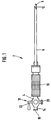
- Fig. 1 is an insufflation needle 2 with a base body 4, one Cannula 6 and one arranged within the cannula 6 Insufflation lance 8 shown.
- the cannula 6 is on a cannula holder 10 attached with which the cannula 6 is attached to the base body 4.
- the cannula holder 10 has a cylindrical shape and has a lengthways and cross-corrugated outer surface. It also serves as a grip the cannula 6 and the insufflation needle 2 when piercing.
- Base body 4 and insufflation lance 8 are relative to the cannula 6 and the carrier body 10 is longitudinally displaceable, being so resilient are biased that an outflow opening 12 in the unloaded state at the front end area of the insufflation lance 8 from the cannula 6 is uncovered.
- this can be pressed back into the cannula 6, so that the Outflow opening 12 is covered.
- FIG. 2 shows the in more detail Structure of the insufflation needle 2.
- the fastening sleeve 24 has a fastening device 26, for example a thread, with a fastening of the cannula holder 10 to the fastening sleeve 24 takes place.
- the mounting sleeve 24 itself is against twisting compared to the base body 4, for example, by one shown, set in a guide groove movable pin.
- the Fastening sleeve 24 has a cylindrical shape and one continuous, concentric bore and is on one cylindrical guide extension 28 (the outer contour of part is shown schematically) of the base body 4 longitudinally displaceable appropriate.
- a spring 30 is for resiliently biasing the Fastening sleeve 24 and thus the cannula holder 10 and the cannula 6 provided relative to the insufflation lance 8 and the base body 4.
- the insufflation lance 8 is soldered into a socket 32.
- the socket 32 is detachable with a fastening device on the guide extension 28 of the base body 4 attached. You can see the pins 34 and 36 one Bayonet lock, which the socket 32 and thus the Set insufflational lance 8 in a groove in the guide extension 28.
- At the socket 32 there is also a circumferential stop 38 for the spring 30 and an insertion cone 40, which the insertion of the socket 32 facilitated in the guide extension 28.
- An exit from Insufflation gas between the guide extension 28 and the socket 32 the use of the insufflation needle is not wanted and is through a seal is guaranteed at this point.
- a channel 42 through the base body 4 is from the inflow opening 16 up to the end of the guide extension 28 as a bore constant diameter. Closes on channel 42 aerodynamically a passage inside the insufflation lance, so that the inflow opening 16 in the base body 4 with the Outflow opening 12 from the insufflation lance 8 in Flow connection is established when the shut-off valve 18 is open.
- the cannula 6 is detachable with the cannula holder 10 two-thread quick connection, a so-called LL connection, connected as shown at 44.
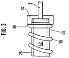
- Fig. 3 shows an alternative way of fastening the socket 32 and the insufflation needle 8 on the guide extension 28 of the Base body 4.
- the socket 32 is in the manner of a union nut the guide extension 28 is formed and is by a Screw connection attached to the guide extension 28.
- the insertion cone is 40 unlike in the embodiment of FIG. 2 as an inner cone educated.
- the socket 32 can also be used as a union nut as shown here is formed with one of the preceding quick connections the guide extension 28 of the base body 4 can be attached. Likewise can the socket 32 of FIG. 2 can be fastened with a screw connection.
- the socket 32 is a financially inexpensive to manufacture Metal rotating body into which the insufflation lance 8 is soldered.
- the But socket 32 can also be made of a plastic material, into which the insufflation lance 8 is glued, or for example in Injection molding process was cast on the insufflation lance 8.
Landscapes
- Health & Medical Sciences (AREA)
- Life Sciences & Earth Sciences (AREA)
- Anesthesiology (AREA)
- Biomedical Technology (AREA)
- Heart & Thoracic Surgery (AREA)
- Hematology (AREA)
- Engineering & Computer Science (AREA)
- Animal Behavior & Ethology (AREA)
- General Health & Medical Sciences (AREA)
- Public Health (AREA)
- Veterinary Medicine (AREA)
- Infusion, Injection, And Reservoir Apparatuses (AREA)
- Surgical Instruments (AREA)
- Laser Surgery Devices (AREA)
Applications Claiming Priority (2)
| Application Number | Priority Date | Filing Date | Title |
|---|---|---|---|
| DE19726579 | 1997-06-23 | ||
| DE19726579A DE19726579A1 (de) | 1997-06-23 | 1997-06-23 | Insufflationsnadel |
Publications (2)
| Publication Number | Publication Date |
|---|---|
| EP0885622A1 true EP0885622A1 (fr) | 1998-12-23 |
| EP0885622B1 EP0885622B1 (fr) | 2000-10-18 |
Family
ID=7833362
Family Applications (1)
| Application Number | Title | Priority Date | Filing Date |
|---|---|---|---|
| EP98106065A Expired - Lifetime EP0885622B1 (fr) | 1997-06-23 | 1998-04-02 | Aiguille à insufflation |
Country Status (3)
| Country | Link |
|---|---|
| EP (1) | EP0885622B1 (fr) |
| AT (1) | ATE196995T1 (fr) |
| DE (3) | DE19726579A1 (fr) |
Citations (2)
| Publication number | Priority date | Publication date | Assignee | Title |
|---|---|---|---|---|
| EP0339945A2 (fr) * | 1988-04-25 | 1989-11-02 | Edwin L. Adair | Aiguille d'insufflation de gaz avec orifice d'introduction d'un instrument |
| US5290276A (en) * | 1992-02-06 | 1994-03-01 | Sewell Jr Frank | Rotatable laparoscopic puncturing instrument |
Family Cites Families (7)
| Publication number | Priority date | Publication date | Assignee | Title |
|---|---|---|---|---|
| DE2835812A1 (de) * | 1978-08-16 | 1980-02-28 | Storz Karl | Trokar |
| GB8914728D0 (en) * | 1989-06-27 | 1989-08-16 | Rocket Of London Ltd | A pneumoperitoneal needle |
| US5139482A (en) * | 1990-01-18 | 1992-08-18 | Simeon Paula S | Fluid infusion line monitor |
| US5104382A (en) * | 1991-01-15 | 1992-04-14 | Ethicon, Inc. | Trocar |
| GB9113102D0 (en) * | 1991-06-18 | 1991-08-07 | Rocket Of London Ltd | A lock device |
| AU651745B2 (en) * | 1991-12-13 | 1994-07-28 | Covidien Ag | Locking pneumoneedle |
| WO1996001132A1 (fr) * | 1994-07-01 | 1996-01-18 | Northgate Technologies Incorporated | Instrument permettant une insufflation a grand debit et destine a une laparoscopie |
-
1997
- 1997-06-23 DE DE19726579A patent/DE19726579A1/de not_active Ceased
-
1998
- 1998-04-02 DE DE29806072U patent/DE29806072U1/de not_active Expired - Lifetime
- 1998-04-02 AT AT98106065T patent/ATE196995T1/de not_active IP Right Cessation
- 1998-04-02 EP EP98106065A patent/EP0885622B1/fr not_active Expired - Lifetime
- 1998-04-02 DE DE59800304T patent/DE59800304D1/de not_active Expired - Lifetime
Patent Citations (2)
| Publication number | Priority date | Publication date | Assignee | Title |
|---|---|---|---|---|
| EP0339945A2 (fr) * | 1988-04-25 | 1989-11-02 | Edwin L. Adair | Aiguille d'insufflation de gaz avec orifice d'introduction d'un instrument |
| US5290276A (en) * | 1992-02-06 | 1994-03-01 | Sewell Jr Frank | Rotatable laparoscopic puncturing instrument |
Also Published As
| Publication number | Publication date |
|---|---|
| EP0885622B1 (fr) | 2000-10-18 |
| DE19726579A1 (de) | 1999-01-28 |
| DE29806072U1 (de) | 1998-05-28 |
| ATE196995T1 (de) | 2000-11-15 |
| DE59800304D1 (de) | 2000-11-23 |
Similar Documents
| Publication | Publication Date | Title |
|---|---|---|
| EP0679408B1 (fr) | Appareil pour introduire un cathéter dans une cavité du corps | |
| DE69211421T2 (de) | Pneumoperitoneum-Nadel | |
| DE2915425C2 (de) | Saugsteuervorrichtung für ein Endoskop | |
| DE69330374T2 (de) | Injektor und dessen anwendung | |
| DE3518547C2 (de) | Hohlnadel eines Biopsiebestecks | |
| DE3500444C2 (de) | Vorrichtung zum Einführen eines Endoskops oder eines chirurgischen Werkzeugs in Körperhöhlen mit einer Zufuhr für ein Spülmedium und einer Absaugung für dieses Spülmedium | |
| DE69704089T2 (de) | Aus einer Nadel mit mehreren Querschnitten und einem elastischen Pfropfen bestehende Einheit für eine medizinische Vorrichtung | |
| DE69328254T2 (de) | Thorakozentese hülsenkatheter | |
| DE69215396T2 (de) | Desinfektierende Kupplung für Katheter und dergleichen | |
| EP0454816A1 (fr) | Dispositif d'injection. | |
| EP0843536B1 (fr) | Instrument chirurgical | |
| DE2701929B2 (de) | Schutzrohr für eine Kanüle einer Biopsienadel | |
| EP1269925B1 (fr) | Canule d'accès pour une opération endoscopique, notamment pour l'arthroscopie | |
| DE2717434A1 (de) | Vorrichtung zur pruefung der eindringtiefe einer hohlnadel in den koerper eines patienten | |
| DE2845643A1 (de) | Katheteranschlusskopf mit mindestens einem kanal in einem grundkoerper | |
| EP1259272A1 (fr) | Dispositif de microperfusion | |
| DE9112550U1 (de) | Trokarhülse zum Durchführen eines medizinischen Instrumentes | |
| DE19832834A1 (de) | Sicherheits-Infusions-Katheternadel | |
| DE2831267A1 (de) | Verbindungsstueck zur verbindung einer injektionsspritze mit einem katheter | |
| EP3846697B1 (fr) | Instrument chirurgical destiné à introduire de façon orientée une substance thérapeutique dans une cavité et outil s'y rapportant | |
| EP1315461A1 (fr) | Dispositif pour etancheifier et lubrifier des instruments guides dans des gaines de trocart | |
| EP0885622B1 (fr) | Aiguille à insufflation | |
| DE102019202158A1 (de) | Ein ophthalmologisches Handgerät sowie ein Set umfassend ein ophthalmologisches Handgerät | |
| DE29509729U1 (de) | Adapterhülse und Katheter-Set mit einer solchen Adapterhülse | |
| DE2835812A1 (de) | Trokar |
Legal Events
| Date | Code | Title | Description |
|---|---|---|---|
| PUAI | Public reference made under article 153(3) epc to a published international application that has entered the european phase |
Free format text: ORIGINAL CODE: 0009012 |
|
| 17P | Request for examination filed |
Effective date: 19981019 |
|
| AK | Designated contracting states |
Kind code of ref document: A1 Designated state(s): AT BE DE ES FR GB GR IT NL |
|
| AX | Request for extension of the european patent |
Free format text: AL;LT;LV;MK;RO;SI |
|
| GRAG | Despatch of communication of intention to grant |
Free format text: ORIGINAL CODE: EPIDOS AGRA |
|
| 17Q | First examination report despatched |
Effective date: 19990707 |
|
| AKX | Designation fees paid |
Free format text: AT BE DE ES FR GB GR IT NL |
|
| GRAG | Despatch of communication of intention to grant |
Free format text: ORIGINAL CODE: EPIDOS AGRA |
|
| GRAG | Despatch of communication of intention to grant |
Free format text: ORIGINAL CODE: EPIDOS AGRA |
|
| GRAH | Despatch of communication of intention to grant a patent |
Free format text: ORIGINAL CODE: EPIDOS IGRA |
|
| GRAH | Despatch of communication of intention to grant a patent |
Free format text: ORIGINAL CODE: EPIDOS IGRA |
|
| GRAA | (expected) grant |
Free format text: ORIGINAL CODE: 0009210 |
|
| AK | Designated contracting states |
Kind code of ref document: B1 Designated state(s): AT BE DE ES FR GB GR IT NL |
|
| PG25 | Lapsed in a contracting state [announced via postgrant information from national office to epo] |
Ref country code: NL Free format text: LAPSE BECAUSE OF FAILURE TO SUBMIT A TRANSLATION OF THE DESCRIPTION OR TO PAY THE FEE WITHIN THE PRESCRIBED TIME-LIMIT Effective date: 20001018 Ref country code: IT Free format text: LAPSE BECAUSE OF FAILURE TO SUBMIT A TRANSLATION OF THE DESCRIPTION OR TO PAY THE FEE WITHIN THE PRESCRIBED TIME-LIMIT;WARNING: LAPSES OF ITALIAN PATENTS WITH EFFECTIVE DATE BEFORE 2007 MAY HAVE OCCURRED AT ANY TIME BEFORE 2007. THE CORRECT EFFECTIVE DATE MAY BE DIFFERENT FROM THE ONE RECORDED. Effective date: 20001018 Ref country code: GB Free format text: LAPSE BECAUSE OF FAILURE TO SUBMIT A TRANSLATION OF THE DESCRIPTION OR TO PAY THE FEE WITHIN THE PRESCRIBED TIME-LIMIT Effective date: 20001018 Ref country code: FR Free format text: LAPSE BECAUSE OF FAILURE TO SUBMIT A TRANSLATION OF THE DESCRIPTION OR TO PAY THE FEE WITHIN THE PRESCRIBED TIME-LIMIT Effective date: 20001018 Ref country code: ES Free format text: THE PATENT HAS BEEN ANNULLED BY A DECISION OF A NATIONAL AUTHORITY Effective date: 20001018 |
|
| REF | Corresponds to: |
Ref document number: 196995 Country of ref document: AT Date of ref document: 20001115 Kind code of ref document: T |
|
| REF | Corresponds to: |
Ref document number: 59800304 Country of ref document: DE Date of ref document: 20001123 |
|
| PG25 | Lapsed in a contracting state [announced via postgrant information from national office to epo] |
Ref country code: GR Free format text: LAPSE BECAUSE OF FAILURE TO SUBMIT A TRANSLATION OF THE DESCRIPTION OR TO PAY THE FEE WITHIN THE PRESCRIBED TIME-LIMIT Effective date: 20010119 |
|
| NLV1 | Nl: lapsed or annulled due to failure to fulfill the requirements of art. 29p and 29m of the patents act | ||
| EN | Fr: translation not filed | ||
| PG25 | Lapsed in a contracting state [announced via postgrant information from national office to epo] |
Ref country code: AT Free format text: LAPSE BECAUSE OF NON-PAYMENT OF DUE FEES Effective date: 20010402 |
|
| GBV | Gb: ep patent (uk) treated as always having been void in accordance with gb section 77(7)/1977 [no translation filed] |
Effective date: 20001018 |
|
| PG25 | Lapsed in a contracting state [announced via postgrant information from national office to epo] |
Ref country code: BE Free format text: LAPSE BECAUSE OF NON-PAYMENT OF DUE FEES Effective date: 20010430 |
|
| PLBE | No opposition filed within time limit |
Free format text: ORIGINAL CODE: 0009261 |
|
| STAA | Information on the status of an ep patent application or granted ep patent |
Free format text: STATUS: NO OPPOSITION FILED WITHIN TIME LIMIT |
|
| 26N | No opposition filed | ||
| BERE | Be: lapsed |
Owner name: G.- FUR WISSENSCHAFTLICHEN APPARATEBAU M.B.H. WIS Effective date: 20010430 |
|
| REG | Reference to a national code |
Ref country code: DE Ref legal event code: R082 Ref document number: 59800304 Country of ref document: DE |
|
| REG | Reference to a national code |
Ref country code: DE Ref legal event code: R082 Ref document number: 59800304 Country of ref document: DE Representative=s name: GRUENECKER PATENT- UND RECHTSANWAELTE PARTG MB, DE Effective date: 20130206 Ref country code: DE Ref legal event code: R082 Ref document number: 59800304 Country of ref document: DE Representative=s name: GRUENECKER, KINKELDEY, STOCKMAIR & SCHWANHAEUS, DE Effective date: 20130206 Ref country code: DE Ref legal event code: R081 Ref document number: 59800304 Country of ref document: DE Owner name: WISAP MEDICAL TECHNOLOGY GMBH, DE Free format text: FORMER OWNER: WISAP GESELLSCHAFT FUER WISSENSCHAFTLICHEN APPARATEBAU MBH, 82054 SAUERLACH, DE Effective date: 20130220 |
|
| PGFP | Annual fee paid to national office [announced via postgrant information from national office to epo] |
Ref country code: DE Payment date: 20170915 Year of fee payment: 20 |
|
| REG | Reference to a national code |
Ref country code: DE Ref legal event code: R071 Ref document number: 59800304 Country of ref document: DE |