EP0885535B1 - Utilisation de paquets d'energie pour reseaux hertziens - Google Patents
Utilisation de paquets d'energie pour reseaux hertziens Download PDFInfo
- Publication number
- EP0885535B1 EP0885535B1 EP97912404A EP97912404A EP0885535B1 EP 0885535 B1 EP0885535 B1 EP 0885535B1 EP 97912404 A EP97912404 A EP 97912404A EP 97912404 A EP97912404 A EP 97912404A EP 0885535 B1 EP0885535 B1 EP 0885535B1
- Authority
- EP
- European Patent Office
- Prior art keywords
- station
- energy
- burst
- time
- remote
- Prior art date
- Legal status (The legal status is an assumption and is not a legal conclusion. Google has not performed a legal analysis and makes no representation as to the accuracy of the status listed.)
- Expired - Lifetime
Links
- 238000012546 transfer Methods 0.000 claims description 25
- 238000000034 method Methods 0.000 claims description 21
- 230000005540 biological transmission Effects 0.000 description 26
- 238000004891 communication Methods 0.000 description 12
- 238000001514 detection method Methods 0.000 description 4
- 238000010586 diagram Methods 0.000 description 4
- 230000008569 process Effects 0.000 description 3
- 230000011664 signaling Effects 0.000 description 3
- 230000002411 adverse Effects 0.000 description 2
- 230000008901 benefit Effects 0.000 description 2
- 230000008859 change Effects 0.000 description 2
- 230000000694 effects Effects 0.000 description 2
- 230000007420 reactivation Effects 0.000 description 2
- 230000004044 response Effects 0.000 description 2
- 230000001360 synchronised effect Effects 0.000 description 2
- 238000013329 compounding Methods 0.000 description 1
- 238000012937 correction Methods 0.000 description 1
- 238000013461 design Methods 0.000 description 1
- 238000011161 development Methods 0.000 description 1
- 238000005516 engineering process Methods 0.000 description 1
- 230000002401 inhibitory effect Effects 0.000 description 1
- 238000009434 installation Methods 0.000 description 1
- 238000005259 measurement Methods 0.000 description 1
- 238000012544 monitoring process Methods 0.000 description 1
- 230000010411 postconditioning Effects 0.000 description 1
- 238000012545 processing Methods 0.000 description 1
- 239000000725 suspension Substances 0.000 description 1
Images


Classifications
-
- H—ELECTRICITY
- H04—ELECTRIC COMMUNICATION TECHNIQUE
- H04W—WIRELESS COMMUNICATION NETWORKS
- H04W74/00—Wireless channel access, e.g. scheduled or random access
- H04W74/04—Scheduled or contention-free access
-
- H—ELECTRICITY
- H04—ELECTRIC COMMUNICATION TECHNIQUE
- H04W—WIRELESS COMMUNICATION NETWORKS
- H04W56/00—Synchronisation arrangements
- H04W56/001—Synchronization between nodes
- H04W56/0015—Synchronization between nodes one node acting as a reference for the others
-
- H—ELECTRICITY
- H04—ELECTRIC COMMUNICATION TECHNIQUE
- H04W—WIRELESS COMMUNICATION NETWORKS
- H04W74/00—Wireless channel access, e.g. scheduled or random access
- H04W74/002—Transmission of channel access control information
Definitions
- the invention relates to a method for data transfer between a master station and at least one remote station of a group of remote stations and comprising the step of
- the invention also relates to a master station and to a remote station.
- communication networks are formed by interconnecting devices by wire or cable, and having each device conform to a protocol for sending messages along these wires and cables.
- a portion of such a network may be implemented as a wireless connection, employing radio or infrared frequency signals between nodes.
- Such wireless connections are point-to-point, having a single communications device at each end, each tuned to each other at a frequency different from other devices in the same geographic area.
- a wireless network is formed without physical connections among the devices, employing, for example, radio frequency signals.
- Each device on the network is tuned to the same frequency, and each device conforms to a protocol for sending messages at this common frequency.
- the protocol may allow communication among all the devices in the network or the protocol may constrain each device to only communicate with a master device.
- Wireless networks offer a significant logistical advantage over wired networks, by obviating the need to run wires or cables to each device.
- LANs Local Area Networks
- a central base station may provide wireless services, including voice, video, and data, to all the communications devices in one's home, or a wireless base station may provide for the communication among all the portable computers in an office, or all the computers on a campus.
- the techniques and protocols employed in these wireless networks must not be significantly inferior to their wired network equivalents.
- a common protocol employed for data communications in a wired network is a bus structure with a "broadcast" protocol.
- Devices on the bus monitor the bus, wait for a quiet period, then transmit. Collisions occur when a second device, having also waited for the quiet period, simultaneously begins to transmit.
- the broadcast protocol typically calls for the devices to cease transmission in the event of a collision, and try again at the next quiet period. Repeated collisions are avoided by having the devices each randomly change their time of response from the start of the quiet period, so that they will no longer respond simultaneously.
- This broadcast protocol as the name implies, has its roots in radio transmission, and is still widely used for voice wireless networks, such as CB radios.
- the broadcast protocol is unsuitable for high speed data communications on a wireless network because collision detection on a wireless network is time-consuming.
- the protocol typically calls for an active assertion of one logic level, but the passive assertion (i.e. a non-assertion of the active level) of the other level. Collisions are detectable at the transmitter by monitoring the bus during the transmission of a passive level. If an active level is detected during this transmitter's transmission of a passive level, it necessarily implies a collision. The wired transmitter can automatically retransmit the message at the next quiet period.
- a device transmitting on a wireless network is unable to detect whether another device is transmitting at the same time.
- the device transmitting if it monitors the transmission frequency, will only detect its own transmission, because its power level will be significantly higher than that of a remote transmitter.
- the intended receiver typically receives a garbled message caused by the simultaneous transmission by two transmitters on the same frequency. Because collisions are likely to occur, and the transmitter has no means to detect these collisions, the wireless broadcast protocol typically requires the intended receiver to acknowledge (ACK) the receipt of each message. If it doesn't receive the message, or receives a garbled message, it doesn't transmit the acknowledgement, or transmits a Not-acknowledged (NAK) signal. If the transmitter fails to receive an acknowledgement, it retransmits the prior message.
- ACK acknowledge
- Polling network protocols wherein a master device polls each of the other devices for messages, are applicable to wireless networks. Such protocols, however, are inherently inefficient for networks with uneven traffic patterns. During the polling process, each device on the network is queried, and the polling of inactive devices consumes time. Most polling protocols allow for the suspension of the polling of a device after some period of inactivity, to save time, but such protocols must also include a means for the unpolled device to notify the master device when it becomes active again. Often this reactivation notification is accomplished by providing an auxiliary connection to the master device, for example an interrupt line common to all devices. The equivalent of an additional auxiliary connection in a wired network is an additional auxiliary frequency in a wireless network.
- a period of time can be set aside in each message period for a notification signal.
- the occurrence of a reactivation notification on this common line, or during the notification period, causes the master device to repoll all the devices on the network to determine which device is now active.
- D1 discloses a method for data transfer between a base station (master station) and at least one mobile station of a group of mobile stations (remote stations). This method comprises the step of exchanging a burst of energy between the master station and the at least one remote station. Thereto, a burst of energy is transmitted from the base station to the mobile station, and in response the mobile station transmits an acknowledging burst of energy to the base station.
- each burst comprises an (abbreviated) identifier for identifying the mobile station. Such an identifier, even when being abbreviated, is disadvantageous in that the burst transmission and reception then become complex.
- a burst in a predefined sub time interval is an indication that a data transfer is going to take place (during the third period of time) between the master station and a predefined remote station, whereby the predefined sub time interval has been assigned to this predefined remote station.
- the synchronization pattern is to be sent to the remotes. As a result, said problem is solved.
- D2 (US-A-5410588) discloses synchronized base stations. The synchronizing of base stations has nothing to do with the invention.
- the invention describes a method for transmitting control information in short energy bursts within a wireless network protocol.
- control information on a network typically comprises short messages with minimal, albeit important, information. That is, control information is typically that which, on a wired network, might be implemented on a single wire having one of two states.
- a "Request to Send” line might be provided on a wired network for a device to notify the master device that it has information to send.
- a "Clear to Send” line might be provide to notify the device that transmission can begin, or, the same "Request to Send” line could be employed by the master to signal this "Clear to Send” message at a subsequent time period.
- an "Acknowledge” line might also be provided.
- the information content comprises a single bit of information: either the device has, or has not, something to send; either the message was received, or it was not received; etc.
- the data content communicated in a wireless network is expected to contain significantly more information. Employing the same protocol for both data and control is inefficient in one or the other protocols, or both.
- This invention provides for a very efficient and effective means for communicating single bit control information messages within a wireless network without necessarily limiting or affecting the protocol employed for effective data transfer.
- This efficient and effective communications means is effected by synchronizing all devices to a master device, and allocating a small unit of time, relative to the synchronous period, to each device.
- the presence, or absence, of energy at the network frequency during each device's allocated time will signify the state of the one bit of control information for that device.
- the presence of energy in the allocated time slot can be asserted by either the master device or each of the other devices.
- multiple control bits can be accommodated by multiple allocations of time, as required.
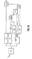
- Figure 1 shows a wireless network, comprised of mobile stations 101 through 105, and a base station 110.
- the mobile station equipment can either be discrete, or incorporated directly into the destination device, such as a telephone.
- Each mobile station on this network is assigned an address.
- address 1 is assigned to mobile station 101, address 2 to station 102, etc.
- the assignment of addresses can be established either by setting switches on each device, or by communicating messages which instruct the device to change its internal address.
- additional devices can be added to the network, or existing devices deleted, through the use of these address assigning and changing messages. Techniques are commonly known for such address initialization and are not presented herein.
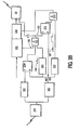
- Figure 2 shows a protocol for transmitting to a base station in a wireless network in accordance with this invention.
- the base station 110 will transmit a synchronizing pattern, which will be used by each station to establish a common time reference 200.
- the second period of time 260 is subdivided into sub time intervals 201 through 205. These time intervals are assigned to each mobile station 101 through 105, corresponding to their addresses 1 through 5. These time intervals are, for efficiency, of very short duration, and each has a fixed relationship to the time 200 established by the master station. If a mobile station has a message to transmit to the base station, it will transmit a burst of energy at the network frequency during its assigned time slot.
- mobile station 103 if mobile station 103 has information to transmit, it will transmit a burst of energy during time interval 203, informing the base station that the mobile station with address 3 has information to send.
- time period 270 data transfer can be accomplished, using the protocol established for such data transfer, independent of this energy burst signalling protocol.
- This particular embodiment is particularly well suited to a network with a relative ranking of mobile stations, wherein messages from address 1 have priority over messages from address 2, address 2 messages have priority over address 3 messages, etc.
- the protocol could require that a mobile station not transmit an energy burst if an energy burst is detected preceding its assigned time slot. That is, if address 2 sends an energy burst, addresses 3 through 5 would not be allowed to send an energy burst. In so doing, the possibility of collision is eliminated, and the station which sent the energy burst would be free to send its data in the immediately following time period 270. The receiving base station would know that the data came from the address corresponding to the time interval of the detected energy burst.
- the base station 110 will transmit a synchronization pattern to the mobile stations, on the frequency assigned for receiving information from the base station, during time period 250.
- the base station will transmit an energy burst during the time interval assigned to the station intended to receive the message.
- the mobile station which corresponds to the time interval in which the energy burst occurred would thus be alerted to receive the subsequent data, transmitted by the base station during time period 270.
- this protocol is particularly well suited for messages intended for more than one mobile station. An energy burst for each of the intended stations can be transmitted during period 260, so that each are alerted to receive the subsequent data transmitted during period 270.
- This protocol is similar in concept to protocols which include the source and/or destination addresses within the message data, but offers significant advantages through the use of energy bursts, as herein described.
- An energy burst as the name implies, is a short burst of energy transmitted at the assigned radio frequency. Contrary to a data signal, this energy burst has a very easy to satisfy criteria.
- Existing digital devices are very well suited for precise time measurements, particularly with reference to a periodically asserted synchronization pattern. Thus, specifying time as the relevant criteria, rather than content, allows for a very cost effective solution. Rather than specifying content-related criteria, as must be done for data signals, the critical specification is merely when the signal occurs, and not its content.
- FIG 3 shows a device for the reception or transmission of control information through the use of energy bursts at specified times, in accordance with this invention.
- the energy pulse detector 302 is shown separate from the data demodulator 301, exemplifying the fact that energy burst detection does not require the signal processing typically applied for data reception.
- the receiver 300 receives a signal from, for example, a base station 110.
- a timing generator 303 provides a means for detecting the sync signal 250 and establishing the time reference 200 of figure 2.
- the timing generator 303 produces a pulse at time 200 on Ref 350. This ref signal resets the RS latch 313, and is also input to delay elements 310 and 311.
- the delay element 310 produces a pulse 380 after a predetermined time from receipt of the pulse on Ref 350.
- the predetermined time is determined by the address assigned to each device, so as to correspond, in time, with one of the time intervals 201 through 205 shown in figure 2.
- This pulse 380 is input to the And gate 312. Also input to the And gate 312 is the output of the detector 302. If an energy pulse is detected during the period assigned to this device, as signalled by pulse 380, the output of the And gate 312 sets the RS Latch 313. Through the establishment of specific time intervals for each addressed device, the output of the RS Latch 313, therefore corresponds to the detection of a control signal from the base station intended for this device.
- the detection of this control signal informs the device that the subsequent message from the base station 100 is intended for this device.
- the delay element 311 generates a signal 381 after a predetermined time from receipt of the pulse on Ref 350. This signal 381 is asserted for the duration of message time period 270.
- the And gate 314 thus enables the gate 315 during the message time period 270 if and only if the RS Latch had been set, as described above, by the receipt of an energy burst during the assigned time period.
- Figure 3b shows a control device for generating an energy burst from a remote transmitter in accordance with this invention. Items having the same function as described in figure 3a have the same reference numerals.
- the reference signal 350 will contain a pulse at a time reference 200 established by the base station's transmission of a sync signal 250.
- the RS Latch 313 will be reset by the occurrence of the pulse on reference signal 350.
- the delay element 310 will produce a pulse during the device's assigned time interval, one of 201 through 205.
- Figure 3b contains an additional latch 330. This latch 330 is used to signal the occurrence of an energy burst prior to the time allocated for this device. The latch 330 is set by the reference signal 350.
- the latch 330 is reset. Thus, at the time of the pulse 380, the output of the latch 330 will be asserted if and only if no energy bursts have been detected since the latch was set by the reference pulse.
- the time interval pulse 380, the output of latch 330, and a control signal 382 are input to And gate 312.
- the And gate 312 will set the latch 313 during the time period 380 only if the latch 330 is set, signalling that no other transmitter sent an energy burst before time 380, and control signal 382 is asserted.
- the output of And gate 312 is also provided to the transmitter 337 as signal 385.
- the transmitter 337 Upon receipt of an asserted signal 385, the transmitter 337 will be enabled, thereby sending an energy burst.
- the detector 302 will subsequently detect this burst, which will cause latch 330 to reset, which will cause the And gate to deassert signal 385, thereby terminating the transmission of the energy burst.
- the signal 385 will be deasserted at the end of timing interval pulse 380.
- the control signal 382 is asserted whenever the device has a message to transmit, and the transmission of this message is effected after sending the above described energy burst.
- Messages are queued in transmit buffer 335.
- buffer 335 asserts the control signal 382.
- This control signal 382 causes the generation of an energy burst during the time period assigned to this device, as described above.
- the enabling of the transmission of the energy burst also sets latch 313, the output of which is input to And gate 314.
- the delay element 311 asserts a signal 381 during the message period 270. If latch 313 is set during this period, the And gate 314 asserts an enabling signal to the gate 336, which effects the transmission of the contents of the transmit buffer 335. If there are no additional messages queued, the transmit buffer 335 deasserts the control signal 382, thereby inhibiting the subsequent transmission of an energy burst.
- FIG. 3 demonstrate the use of energy bursts for receiving and transmitting control signals which subsequently control the reception and transmission of messages.
- the same, or similar, logic could be employed to receive or transmit energy bursts at the appropriate time intervals corresponding to other control signals as well.
- the common elements of figures 3a and 3b can be combined, and the embodiment shown could be implemented and executed by a software program, or a combination of hardware and software, as would be evident to one skilled in the art.
- the energy burst transmission and reception can be accomplished without the data equalization techniques normally employed for reliable, error free, data transmission.
- the automatic gain control, signal pre- and post- conditioning, error correction, and other techniques required to reliably determine which of two or more values have been received during data transmission, are not required to determine whether or not a burst of energy occurred at a particular time.
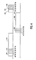
- FIG. 4 shows a protocol which eliminates this redundant process.
- the base station transmits a synchronizing pattern, on the one frequency used for both transmission and reception.
- This synchronizing pattern establishes a time reference 400.
- Time period 460 contains time intervals 461 through 465, corresponding to mobile station addresses 1 through 5.
- the base station transmits one or more energy bursts during the time interval corresponding to the intended receiving mobile station(s).
- Time period 480 is also partitioned into time periods 481 through 485, corresponding to mobile station addresses 1 through 5. If a mobile station has data to transmit, it transmits an energy burst during its assigned time interval, relative to time reference 400. As previously described, the protocol for transmitting to the base station would dictate that a mobile station not transmit an energy burst if it detects an energy burst in time intervals prior to its assigned interval. The mobile station which transmits the energy burst would then subsequently transmits its data during time period 490.
- the prior embodiments demonstrate the use of energy burst transmissions for predominantly single addressee communications. That is, within the time frames previously described, one remote station transmits data to the base station, and, except in the case of multiple addressees for the same message, the base station transmits data to one remote station. In such protocols, there is one energy burst period per message, and, in a network with heavy traffic, such a protocol may be inefficient.
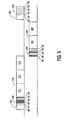
- Figure 5 shows an embodiment of the subject invention, particularly well suited for networks with continually heavy traffic patterns.
- the periods 570 and 590 following the energy burst periods 560 and 580 contain a variable number of message transfer periods. For example, if the base station has messages for three remote stations, three message transfer periods would follow the base stations energy burst period. The base station would assert an energy burst at the time periods assigned to each of the remote stations, and transmit the messages in the same order as the asserted energy bursts.
- Figure 5 shows, for example, that remote stations 2, 3, and 5 have messages being sent from the base station, as signalled by energy bursts at time periods 562, 563 and 565.
- Remote station 2's message will be transmitted first, at message transfer period 571; next, remote station 3's message, at message transfer period 572, followed by remote station 5's message, at period 573.
- Each remote station will note whether its assigned time period contains an energy burst, and also how many energy bursts, for other remote stations, have preceded its burst. In the example given, station 2 will note that it received the first burst, and will therefore know that its message will be the first message from the base station. Similarly, station 3 would note that it received the second burst, and hence its message is the second message. Station 5 would similarly determine that its message is the third message. All stations in this embodiment will note how many messages are being transmitted, by noting how many energy burst are transmitted in period 560.
- the stations will know when the time period 580 begins, relative to the time reference 500.
- the remote stations are not prohibited from asserting an energy burst when another remote station has also asserted an energy burst. If two remote stations have messages to send to the base station, two message transfer periods will follow the remote station energy burst period. Each remote station which has a message to send asserts an energy burst during its assigned time slot in period 580. Each remote station also notes how many other remote stations have transmitted an energy burst before them. If a particular remote station is the first station to transmit an energy burst, it sends its message in the first message slot 591 of period 590. If another remote station notes that one energy burst has preceded its energy burst, it sends its message in the second message slot 592.
- stations 1 and 3 have asserted energy bursts in time slots 581 and 583.
- Station 1 transmits its message in the first message time slot 591.
- Station 3 having noted that one energy burst 581 has preceded its energy burst 583, transmits its message in the second message time slot 592.
- the base station knowing that only two remote stations had messages to send, can immediately recommence the process by transmitting the synchronizing sequence for the next set of messages. Note that if there are no messages from the remote stations, the energy burst time period 580 will not contain any energy bursts and the synchronizing sequence 550 can commence immediately after the energy burst period 580. Similarly, if the base station has no messages to send, energy burst period 580 can begin immediately after energy burst period 560.
- the format of the message transfer protocol is independent of the energy burst timing protocol.
- This invention is not limited to the transfer protocols presented herein.
- explicit addressing could be included within each message.
- the use of energy bursts in this protocol would serve the purpose of collision avoidance, by allocating the message transfer time in accordance with the occurrence of energy bursts, but would not be exclusively relied upon to determine the addressees.
- the energy burst timing protocol could be employed in a network without an explicit base station. Each station could listen to all transmitted messages, and select those messages which contained its assigned address, either as an explicit address, or as determined by the energy burst time interval.
- the energy burst timing protocol would be established by having one station transmit the timing signal, as in a distributed synchronization network, wherein the synchronizing signal is transmitted by any station which initiates the communication.
- the use of the energy burst timing protocol disclosed is not limited to its use as a "request to send” signal as presented above.
- the energy burst timing protocol could be employed to signal other events as well.
- an intervening period could be inserted between the aforementioned "request to send” energy burst period and the message transfer period.
- the intended recipients could utilize energy bursts to signal a corresponding "clear to send” signal.
- energy burst timing protocol as disclosed herein is not limited to networks, nor to wireless networks in particular.
- energy bursts may be used exclusively for acknowledgements.
- energy burst periods could be employed to eliminate signalling wires, by adding one or more burst periods to the message transferring wire.
- the protocol may call for a priority signal, wherein the transmitter assigns a priority, for example from 1 to 3, for each message.
- a priority signal wherein the transmitter assigns a priority, for example from 1 to 3, for each message.
- Two time periods per remote station could be allocated in the energy burst period, and two bits could be transmitted as follows: 00 for no message, 01 for a Priority 1 message, 10 for a Priority 2 message, 11 for a Priority 3 message.
Claims (18)
- Procédé pour un transfert de données entre une station maîtresse (110) et au moins une station éloignée (101) d'un groupe de stations éloignées (101 et 105), et comprenant les étapes :- d'échange d'un paquet d'énergie entre la station maîtresse (110) et la au moins une station éloignée (101) ;caractérisé en ce que le procédé comprend en outre les étapes- d'émission d'un motif de synchronisation de la station maîtresse (110) vers le groupe de stations éloignées (101 à 105) pendant une première période de temps (250) pour établir une référence de temps commune (200) dans chaque station éloignée (101 à 105), une deuxième période de temps (260) étant divisée en des sous-intervalles de temps respectifs (201 à 205), lesquels sous-intervalles de temps respectifs (201 à 205) sont attribués aux stations éloignées respectives (101 à 105), et lesquels sous-intervalles de temps respectifs (201 à 205) ont chacun une relation fixe par rapport à la référence de temps commune (200) ;- d'accomplissement du transfert de données pendant une troisième période de temps (270) ;
le paquet d'énergie étant échangé pendant le sous-intervalle de temps (201) qui a été attribué à la au moins une station éloignée (101). - Procédé selon la revendication 1, le paquet d'énergie comprenant au plus deux bits.
- Procédé selon la revendication 1 ou 2, l'étape d'échange comprenant une sous-étape d'émission du paquet d'énergie de la station maîtresse (110) vers la au moins une station éloignée (101).
- Procédé selon la revendication 3, le transfert de données étant accompli de la station maîtresse (110) vers la au moins une station éloignée (101).
- Procédé selon la revendication 1 ou 2, l'étape d'échange comprenant une sous-étape d'émission du paquet d'énergie de la au moins une station éloignée (101) vers la station maîtresse (110).
- Procédé selon la revendication 5, le transfert de données étant accompli de la au moins une station éloignée (101) vers la station maîtresse (110).
- Station maîtresse (110) pour un transfert de données entre la station maîtresse (110) et au moins une station éloignée (101) d'un groupe de stations éloignées (101 à 105), et comprenant :- des moyens pour échanger un paquet d'énergie entre la station maîtresse et la au moins une station éloignée (101) ;caractérisé en ce que la station maîtresse (110) comprend en outre :- des moyens pour émettre un motif de synchronisation vers le groupe de stations éloignées (101 à 105) pendant une première période de temps (250) afin d'établir une référence de temps commune (200) dans chaque station éloignée (101 à 105), une deuxième période de temps (260) divisée en des sous-intervalles de temps respectifs (201 à 205), lesquels sous-intervalles de temps respectifs (201 à 205) sont attribués aux stations éloignées respectives (101 à 105), et lesquels sous-intervalles de temps respectifs (201 à 205) ont chacun une relation fixe par rapport à la référence de temps commune (200) ;- des moyens pour accomplir le transfert de données pendant une troisième période de temps (270), le paquet d'énergie étant échangé pendant le sous-intervalle de temps (201) qui a été attribuée à la au moins une station éloignée (101).
- Station maîtresse (110) selon la revendication 7, le paquet d'énergie comprenant au moins deux bits.
- Station maîtresse (110) selon la revendication 7 ou 8, les moyens d'échange comprenant des moyens pour émettre le paquet d'énergie vers la au moins une station éloignée (101).
- Station maîtresse (110) selon la revendication 9, les moyens d'accomplissement comprenant des moyens pour émettre les données vers la au moins une station éloignée (101).
- Station maîtresse (110) selon la revendication 7 ou 8, les moyens d'échange comprenant des moyens pour recevoir le paquet d'énergie de la au moins une station éloignée (101).
- Station maîtresse (110) selon la revendication 11, les moyens d'accomplissement comprenant des moyens pour recevoir des données de la au moins une station éloignée (101).
- Station éloignée (101) pour un transfert de données entre une station maîtresse (110) et la station éloignée (101), et comprenant :- des moyens pour échanger un paquet d'énergie entre la station maîtresse (110) et la station éloignée (101) ;caractérisé en ce que la station éloignée (101) comprend en outre :- des moyens pour recevoir un motif de synchronisation de la station maîtresse (110) pendant une première période de temps (250) afin d'établir une référence de temps commune (200) dans la station éloignée (101), une deuxième période de temps (260) étant divisée en sous-intervalles de temps respectifs (201 à 205), lesquels sous-intervalles de temps respectifs (201 à 205) sont attribués à des stations éloignées respectives (101 à 105), et lesquels sous-intervalles de temps respectifs (201 à 205) ont chacun une relation fixe par rapport à la référence de temps commune (200) ;- des moyens pour accomplir le transfert de données pendant une troisième période de temps (270) ;
le paquet d'énergie étant échangé pendant le sous-intervalle de temps (201) qui a été attribuée à la station éloignée (101). - Station éloignée (101) selon la revendication 13, le paquet d'énergie comprenant au moins deux bits.
- Station éloignée (101) selon la revendication 13 ou 14, les moyens d'échange comprenant des moyens pour recevoir le paquet d'énergie de la station maîtresse (110).
- Station éloignée (101) selon la revendication 15, les moyens d'accomplissement comprenant des moyens pour recevoir les données de la station maîtresse (110).
- Station éloignée (101) selon la revendication 13 ou 14, les moyens d'échange comprenant des moyens pour émettre le paquet d'énergie vers la station maîtresse (110).
- Station éloignée (101) selon la revendication 17, les moyens d'accomplissement comprenant des moyens pour émettre les données vers la station maîtresse (110).
Applications Claiming Priority (3)
| Application Number | Priority Date | Filing Date | Title |
|---|---|---|---|
| US767101 | 1996-12-04 | ||
| US08/767,101 US6069901A (en) | 1996-12-04 | 1996-12-04 | Use of energy bursts for wireless networks |
| PCT/IB1997/001491 WO1998025415A2 (fr) | 1996-12-04 | 1997-12-01 | Utilisation de paquets d'energie pour reseaux hertziens |
Publications (2)
| Publication Number | Publication Date |
|---|---|
| EP0885535A2 EP0885535A2 (fr) | 1998-12-23 |
| EP0885535B1 true EP0885535B1 (fr) | 2006-11-29 |
Family
ID=25078483
Family Applications (1)
| Application Number | Title | Priority Date | Filing Date |
|---|---|---|---|
| EP97912404A Expired - Lifetime EP0885535B1 (fr) | 1996-12-04 | 1997-12-01 | Utilisation de paquets d'energie pour reseaux hertziens |
Country Status (9)
| Country | Link |
|---|---|
| US (1) | US6069901A (fr) |
| EP (1) | EP0885535B1 (fr) |
| JP (1) | JP4100714B2 (fr) |
| KR (1) | KR100575011B1 (fr) |
| CN (1) | CN1132353C (fr) |
| BR (1) | BR9707345B1 (fr) |
| DE (1) | DE69737017T2 (fr) |
| ES (1) | ES2277355T3 (fr) |
| WO (1) | WO1998025415A2 (fr) |
Families Citing this family (13)
| Publication number | Priority date | Publication date | Assignee | Title |
|---|---|---|---|---|
| GB9804626D0 (en) * | 1998-03-06 | 1998-04-29 | Philips Electronics Nv | Wireless local area network system |
| GB9821089D0 (en) * | 1998-09-30 | 1998-11-18 | Koninkl Philips Electronics Nv | Method for the communication of information and apparatus employing the method |
| US6967937B1 (en) * | 1999-12-17 | 2005-11-22 | Cingular Wireless Ii, Llc | Collision-free multiple access reservation scheme for multi-tone modulation links |
| US6265975B1 (en) * | 2000-02-25 | 2001-07-24 | Harry I. Zimmerman | Proximity system for baggage |
| DE60128132T2 (de) | 2000-12-11 | 2007-12-27 | Sharp K.K. | Funkkommunikationssystem |
| US20020159434A1 (en) * | 2001-02-12 | 2002-10-31 | Eleven Engineering Inc. | Multipoint short range radio frequency system |
| US7085232B1 (en) | 2001-03-29 | 2006-08-01 | Cisco Technology, Inc. | ARQ in a point to multipoint network |
| US6907028B2 (en) * | 2002-02-14 | 2005-06-14 | Nokia Corporation | Clock-based time slicing |
| GB2403629A (en) * | 2003-06-27 | 2005-01-05 | Nokia Corp | Selective data reception |
| US7660583B2 (en) * | 2004-03-19 | 2010-02-09 | Nokia Corporation | Advanced handover in phased-shifted and time-sliced networks |
| US20090185550A1 (en) * | 2006-05-29 | 2009-07-23 | Panasonic Corporation | Radio base station apparatus |
| US20080108298A1 (en) * | 2006-11-07 | 2008-05-08 | Selen Mats A | Certified two way source initiated transfer |
| DE102012216716A1 (de) | 2012-09-19 | 2014-03-20 | Robert Bosch Gmbh | Kommunikationsverfahren in einem Kommunikationssystem |
Family Cites Families (12)
| Publication number | Priority date | Publication date | Assignee | Title |
|---|---|---|---|---|
| NZ232224A (en) * | 1989-01-27 | 1993-03-26 | British Telecomm | Alternate burst communication for cordless phones: bursts contain synchronisation information |
| US5166929A (en) * | 1990-06-18 | 1992-11-24 | Northern Telecom Limited | Multiple access protocol |
| JP3093243B2 (ja) * | 1990-07-12 | 2000-10-03 | 株式会社東芝 | 移動無線通信システム |
| US5410588A (en) * | 1991-04-03 | 1995-04-25 | Kabushiki Kaisha Toshiba | Mobile radio communications system having a supervising radio transmitting station for transmitting a reference synchronizing signal to a first and second base stations via a radio link |
| US5521925A (en) * | 1993-09-09 | 1996-05-28 | Hughes Aircraft Company | Method and apparatus for providing mixed voice and data communication in a time division multiple access radio communication system |
| JPH0799473A (ja) * | 1993-09-28 | 1995-04-11 | Toshiba Corp | ディジタル移動通信装置 |
| JPH07283773A (ja) * | 1994-04-06 | 1995-10-27 | Fujitsu Ltd | 移動局装置および基地局装置 |
| US5764648A (en) * | 1994-07-20 | 1998-06-09 | Sanyo Electric Co., Ltd. | Method and apparatus for generating a transmission timing signal in a wireless telephone |
| JP2600622B2 (ja) * | 1994-09-22 | 1997-04-16 | 日本電気株式会社 | Tdma方式の移動通信システムにおける下り制御信号の送信制御方法 |
| ES2103190B1 (es) * | 1994-11-30 | 1998-04-01 | Alcatel Standard Electrica | Procedimiento de alineamiento de rafagas. |
| US5745484A (en) * | 1995-06-05 | 1998-04-28 | Omnipoint Corporation | Efficient communication system using time division multiplexing and timing adjustment control |
| US5740166A (en) * | 1996-03-18 | 1998-04-14 | Telefonaktiebolaget Lm Ericsson | United access channel for use in a mobile communications system |
-
1996
- 1996-12-04 US US08/767,101 patent/US6069901A/en not_active Expired - Fee Related
-
1997
- 1997-12-01 CN CN97193291.3A patent/CN1132353C/zh not_active Expired - Fee Related
- 1997-12-01 BR BRPI9707345-8A patent/BR9707345B1/pt not_active IP Right Cessation
- 1997-12-01 EP EP97912404A patent/EP0885535B1/fr not_active Expired - Lifetime
- 1997-12-01 ES ES97912404T patent/ES2277355T3/es not_active Expired - Lifetime
- 1997-12-01 KR KR1019980705976A patent/KR100575011B1/ko not_active IP Right Cessation
- 1997-12-01 DE DE69737017T patent/DE69737017T2/de not_active Expired - Fee Related
- 1997-12-01 JP JP52540598A patent/JP4100714B2/ja not_active Expired - Fee Related
- 1997-12-01 WO PCT/IB1997/001491 patent/WO1998025415A2/fr active IP Right Grant
Also Published As
| Publication number | Publication date |
|---|---|
| BR9707345A (pt) | 2000-10-31 |
| WO1998025415A3 (fr) | 1998-10-01 |
| EP0885535A2 (fr) | 1998-12-23 |
| WO1998025415A2 (fr) | 1998-06-11 |
| KR100575011B1 (ko) | 2006-10-25 |
| CN1214826A (zh) | 1999-04-21 |
| JP4100714B2 (ja) | 2008-06-11 |
| DE69737017T2 (de) | 2007-06-21 |
| BR9707345B1 (pt) | 2009-05-05 |
| ES2277355T3 (es) | 2007-07-01 |
| KR19990082247A (ko) | 1999-11-25 |
| US6069901A (en) | 2000-05-30 |
| DE69737017D1 (de) | 2007-01-11 |
| CN1132353C (zh) | 2003-12-24 |
| JP2000504545A (ja) | 2000-04-11 |
Similar Documents
| Publication | Publication Date | Title |
|---|---|---|
| US5339316A (en) | Wireless local area network system | |
| US5677909A (en) | Apparatus for exchanging data between a central station and a plurality of wireless remote stations on a time divided commnication channel | |
| US5440560A (en) | Sleep mode and contention resolution within a common channel medium access method | |
| US5329531A (en) | Method of accessing a communication medium | |
| US20030137970A1 (en) | System and method for improved synchronization in a wireless network | |
| US7613146B2 (en) | Method and system for reliable data transmission in wireless networks | |
| US6292494B1 (en) | Channel hopping protocol | |
| US20030231621A1 (en) | Dynamic communication channel switching for computer networks | |
| EP0885535B1 (fr) | Utilisation de paquets d'energie pour reseaux hertziens | |
| WO2000016518A9 (fr) | Procede et appareil de commande de communications dans un reseau informatique | |
| EP1112641A2 (fr) | Procede et dispositif permettant d'acceder a un canal de communication dans un reseau informatique | |
| JPH0837528A (ja) | データ通信装置およびその方法 | |
| JP3165125B2 (ja) | 無線通信における多重アクセス方法 | |
| US20030016647A1 (en) | System and method for multipoint to multipoint data communication | |
| CA2245188C (fr) | Utilisation de paquets d'energie pour reseaux hertziens | |
| JP3305268B2 (ja) | 無線マルチキャスト受信局グループ構成方法及び該方法を用いた無線局 | |
| US7324544B1 (en) | Network slot synchronization scheme for a computer network communication channel | |
| CA2379844A1 (fr) | Structure de synchronisation de creneaux temporels de reseau pour canal de communication de reseau informatique | |
| MXPA98006276A (en) | Use of energy bursts for wireless networks | |
| WO2003009518A2 (fr) | Systeme et procede de communication de donnees multipoint a multipoint | |
| CA1208736A (fr) | Dispositif et methode de recherche de noms pour systeme de transmission de donnees a reseau local | |
| CN114630285A (zh) | 一种数据传输方法、设备、系统和计算机可读存储介质 | |
| JP2003333006A (ja) | 無線装置 | |
| US20050043029A1 (en) | Data transmission | |
| WO2000016521A1 (fr) | Architecture hierarchisee de reseau informatique |
Legal Events
| Date | Code | Title | Description |
|---|---|---|---|
| PUAI | Public reference made under article 153(3) epc to a published international application that has entered the european phase |
Free format text: ORIGINAL CODE: 0009012 |
|
| PUAK | Availability of information related to the publication of the international search report |
Free format text: ORIGINAL CODE: 0009015 |
|
| AK | Designated contracting states |
Kind code of ref document: A2 Designated state(s): DE ES FR GB IT |
|
| AK | Designated contracting states |
Kind code of ref document: A3 Designated state(s): DE ES FR GB IT |
|
| RHK1 | Main classification (correction) |
Ipc: H04J 3/12 |
|
| 17P | Request for examination filed |
Effective date: 19990401 |
|
| 17Q | First examination report despatched |
Effective date: 20040506 |
|
| GRAP | Despatch of communication of intention to grant a patent |
Free format text: ORIGINAL CODE: EPIDOSNIGR1 |
|
| GRAS | Grant fee paid |
Free format text: ORIGINAL CODE: EPIDOSNIGR3 |
|
| GRAA | (expected) grant |
Free format text: ORIGINAL CODE: 0009210 |
|
| AK | Designated contracting states |
Kind code of ref document: B1 Designated state(s): DE ES FR GB IT |
|
| REG | Reference to a national code |
Ref country code: GB Ref legal event code: FG4D |
|
| REF | Corresponds to: |
Ref document number: 69737017 Country of ref document: DE Date of ref document: 20070111 Kind code of ref document: P |
|
| ET | Fr: translation filed | ||
| REG | Reference to a national code |
Ref country code: ES Ref legal event code: FG2A Ref document number: 2277355 Country of ref document: ES Kind code of ref document: T3 |
|
| PLBE | No opposition filed within time limit |
Free format text: ORIGINAL CODE: 0009261 |
|
| STAA | Information on the status of an ep patent application or granted ep patent |
Free format text: STATUS: NO OPPOSITION FILED WITHIN TIME LIMIT |
|
| 26N | No opposition filed |
Effective date: 20070830 |
|
| PGFP | Annual fee paid to national office [announced via postgrant information from national office to epo] |
Ref country code: IT Payment date: 20081217 Year of fee payment: 12 |
|
| PGFP | Annual fee paid to national office [announced via postgrant information from national office to epo] |
Ref country code: ES Payment date: 20090128 Year of fee payment: 12 |
|
| PGFP | Annual fee paid to national office [announced via postgrant information from national office to epo] |
Ref country code: DE Payment date: 20090220 Year of fee payment: 12 |
|
| PGFP | Annual fee paid to national office [announced via postgrant information from national office to epo] |
Ref country code: GB Payment date: 20081231 Year of fee payment: 12 |
|
| PGFP | Annual fee paid to national office [announced via postgrant information from national office to epo] |
Ref country code: FR Payment date: 20081219 Year of fee payment: 12 |
|
| GBPC | Gb: european patent ceased through non-payment of renewal fee |
Effective date: 20091201 |
|
| REG | Reference to a national code |
Ref country code: FR Ref legal event code: ST Effective date: 20100831 |
|
| PG25 | Lapsed in a contracting state [announced via postgrant information from national office to epo] |
Ref country code: FR Free format text: LAPSE BECAUSE OF NON-PAYMENT OF DUE FEES Effective date: 20091231 |
|
| PG25 | Lapsed in a contracting state [announced via postgrant information from national office to epo] |
Ref country code: DE Free format text: LAPSE BECAUSE OF NON-PAYMENT OF DUE FEES Effective date: 20100701 |
|
| PG25 | Lapsed in a contracting state [announced via postgrant information from national office to epo] |
Ref country code: GB Free format text: LAPSE BECAUSE OF NON-PAYMENT OF DUE FEES Effective date: 20091201 |
|
| PG25 | Lapsed in a contracting state [announced via postgrant information from national office to epo] |
Ref country code: IT Free format text: LAPSE BECAUSE OF NON-PAYMENT OF DUE FEES Effective date: 20091201 |
|
| REG | Reference to a national code |
Ref country code: ES Ref legal event code: FD2A Effective date: 20110408 |
|
| PG25 | Lapsed in a contracting state [announced via postgrant information from national office to epo] |
Ref country code: ES Free format text: LAPSE BECAUSE OF NON-PAYMENT OF DUE FEES Effective date: 20110324 |
|
| PG25 | Lapsed in a contracting state [announced via postgrant information from national office to epo] |
Ref country code: ES Free format text: LAPSE BECAUSE OF NON-PAYMENT OF DUE FEES Effective date: 20091202 |