EP0885144B1 - Verfahren und computergesteuerte maschine zum anbringen reckbarer etikette auf gegenständen - Google Patents
Verfahren und computergesteuerte maschine zum anbringen reckbarer etikette auf gegenständen Download PDFInfo
- Publication number
- EP0885144B1 EP0885144B1 EP96923231A EP96923231A EP0885144B1 EP 0885144 B1 EP0885144 B1 EP 0885144B1 EP 96923231 A EP96923231 A EP 96923231A EP 96923231 A EP96923231 A EP 96923231A EP 0885144 B1 EP0885144 B1 EP 0885144B1
- Authority
- EP
- European Patent Office
- Prior art keywords
- label
- article
- segment
- applying
- container
- Prior art date
- Legal status (The legal status is an assumption and is not a legal conclusion. Google has not performed a legal analysis and makes no representation as to the accuracy of the status listed.)
- Expired - Lifetime
Links
Images


Classifications
-
- B—PERFORMING OPERATIONS; TRANSPORTING
- B65—CONVEYING; PACKING; STORING; HANDLING THIN OR FILAMENTARY MATERIAL
- B65C—LABELLING OR TAGGING MACHINES, APPARATUS, OR PROCESSES
- B65C9/00—Details of labelling machines or apparatus
-
- B—PERFORMING OPERATIONS; TRANSPORTING
- B65—CONVEYING; PACKING; STORING; HANDLING THIN OR FILAMENTARY MATERIAL
- B65C—LABELLING OR TAGGING MACHINES, APPARATUS, OR PROCESSES
- B65C9/00—Details of labelling machines or apparatus
- B65C9/40—Controls; Safety devices
-
- B—PERFORMING OPERATIONS; TRANSPORTING
- B65—CONVEYING; PACKING; STORING; HANDLING THIN OR FILAMENTARY MATERIAL
- B65C—LABELLING OR TAGGING MACHINES, APPARATUS, OR PROCESSES
- B65C3/00—Labelling other than flat surfaces
- B65C3/06—Affixing labels to short rigid containers
- B65C3/08—Affixing labels to short rigid containers to container bodies
- B65C3/14—Affixing labels to short rigid containers to container bodies the container being positioned for labelling with its centre-line vertical
- B65C3/16—Affixing labels to short rigid containers to container bodies the container being positioned for labelling with its centre-line vertical by rolling the labels onto cylindrical containers, e.g. bottles
-
- B—PERFORMING OPERATIONS; TRANSPORTING
- B65—CONVEYING; PACKING; STORING; HANDLING THIN OR FILAMENTARY MATERIAL
- B65C—LABELLING OR TAGGING MACHINES, APPARATUS, OR PROCESSES
- B65C9/00—Details of labelling machines or apparatus
- B65C9/0015—Preparing the labels or articles, e.g. smoothing, removing air bubbles
-
- B—PERFORMING OPERATIONS; TRANSPORTING
- B65—CONVEYING; PACKING; STORING; HANDLING THIN OR FILAMENTARY MATERIAL
- B65C—LABELLING OR TAGGING MACHINES, APPARATUS, OR PROCESSES
- B65C9/00—Details of labelling machines or apparatus
- B65C9/02—Devices for moving articles, e.g. containers, past labelling station
- B65C9/04—Devices for moving articles, e.g. containers, past labelling station having means for rotating the articles
- B65C9/045—Devices for moving articles, e.g. containers, past labelling station having means for rotating the articles adapted for accommodating articles of different diameters, e.g. for adapting the program of rotation to the diameter of the articles
-
- B—PERFORMING OPERATIONS; TRANSPORTING
- B65—CONVEYING; PACKING; STORING; HANDLING THIN OR FILAMENTARY MATERIAL
- B65C—LABELLING OR TAGGING MACHINES, APPARATUS, OR PROCESSES
- B65C9/00—Details of labelling machines or apparatus
- B65C9/46—Applying date marks, code marks, or the like, to the label during labelling
-
- Y—GENERAL TAGGING OF NEW TECHNOLOGICAL DEVELOPMENTS; GENERAL TAGGING OF CROSS-SECTIONAL TECHNOLOGIES SPANNING OVER SEVERAL SECTIONS OF THE IPC; TECHNICAL SUBJECTS COVERED BY FORMER USPC CROSS-REFERENCE ART COLLECTIONS [XRACs] AND DIGESTS
- Y10—TECHNICAL SUBJECTS COVERED BY FORMER USPC
- Y10T—TECHNICAL SUBJECTS COVERED BY FORMER US CLASSIFICATION
- Y10T156/00—Adhesive bonding and miscellaneous chemical manufacture
- Y10T156/10—Methods of surface bonding and/or assembly therefor
- Y10T156/1002—Methods of surface bonding and/or assembly therefor with permanent bending or reshaping or surface deformation of self sustaining lamina
- Y10T156/1028—Methods of surface bonding and/or assembly therefor with permanent bending or reshaping or surface deformation of self sustaining lamina by bending, drawing or stretch forming sheet to assume shape of configured lamina while in contact therewith
- Y10T156/1033—Flexible sheet to cylinder lamina
-
- Y—GENERAL TAGGING OF NEW TECHNOLOGICAL DEVELOPMENTS; GENERAL TAGGING OF CROSS-SECTIONAL TECHNOLOGIES SPANNING OVER SEVERAL SECTIONS OF THE IPC; TECHNICAL SUBJECTS COVERED BY FORMER USPC CROSS-REFERENCE ART COLLECTIONS [XRACs] AND DIGESTS
- Y10—TECHNICAL SUBJECTS COVERED BY FORMER USPC
- Y10T—TECHNICAL SUBJECTS COVERED BY FORMER US CLASSIFICATION
- Y10T156/00—Adhesive bonding and miscellaneous chemical manufacture
- Y10T156/10—Methods of surface bonding and/or assembly therefor
- Y10T156/1052—Methods of surface bonding and/or assembly therefor with cutting, punching, tearing or severing
- Y10T156/1062—Prior to assembly
-
- Y—GENERAL TAGGING OF NEW TECHNOLOGICAL DEVELOPMENTS; GENERAL TAGGING OF CROSS-SECTIONAL TECHNOLOGIES SPANNING OVER SEVERAL SECTIONS OF THE IPC; TECHNICAL SUBJECTS COVERED BY FORMER USPC CROSS-REFERENCE ART COLLECTIONS [XRACs] AND DIGESTS
- Y10—TECHNICAL SUBJECTS COVERED BY FORMER USPC
- Y10T—TECHNICAL SUBJECTS COVERED BY FORMER US CLASSIFICATION
- Y10T428/00—Stock material or miscellaneous articles
- Y10T428/24—Structurally defined web or sheet [e.g., overall dimension, etc.]
- Y10T428/24802—Discontinuous or differential coating, impregnation or bond [e.g., artwork, printing, retouched photograph, etc.]
Definitions
- the spinning of the container is achieved by, for example, a wheel fixed to and coaxial with the upper member of a pair of chucks and a pad which is concentric to the turret axis. The contact between this wheel and pad causes the respective chuck, and with it the container, to spin.
- the container can spin in only one direction and its speed is fixed by the speed of the turret and by the radius of the wheel and the pad. Also, this method of spinning the container to wrap the label may be ineffective for containers having generally noncircular cross sections.
- Such label application to containers may be carried cut with a stack of precut labels rather than severing labels from a continuous length of label material.
- An alternative to such heat shrinking/contour labelling is the application of stretchable labels, which are stretched before application and which, after application, contract and closely adhere to the recessed and/or contoured portions of the container.
- stretch labelling and the method and machinery for accomplishing it is provided by Automatic Label Systems of Twinsburg, Ohio, who supply what are called "Auto-Sleeve® stretch sleeve labels.”
- the Auto-Sleeve® labels are first formed into sleeves.
- the sleeves have a diameter less than the maximum diameter of the container to which they are to be fitted and the sleeve is stretch fitted over the container and when so applied it contracts and relaxes to fit the container tightly.
- This method avoids the need to use glue, heat or solvent to adhere the label to containers and it avoids the need to heat the label on containers to shrink the label material onto the container.
- stretch label material e.g., stretchable polyethylene is supplied continuously to a cutting instrumentality such as that shown in U.S. Patent No. 4,181,555 and each label, after it passes through the cutter and before it is cut into en individual label is supplied to a rotating vacuum drum and its leading end is placed on the rotating vacuum drum which grips the label by vacuum.
- precut labels are fed from a stack of the same to a vacuum drum, as for example in U.S. Patent No. 4,978,416, likewise being gripped by the vacuum of the vacuum drum.
- the vacuum is provided by a suitable vacuum pump (not shown). Also, means are provided to move the upper of each pair of upper and lower chucks away from the lower chuck to permit entry of a container and downward movement to clamp the container in place between the upper and lower chucks. Suitable cam means for such function is described in U. S. Patent No. 4,108,709, which also serves to lift each upper chuck to release a labeled container.
- a sensor and actuator arrangement capable of sensing upper chuck position and moving the upper chuck accordingly, may also be provided. The sensor and actuator arrangement would be similar to that discussed below with respect to turret 10 and modified as appropriate.
- the actuator may generally be an electric motor or air cylinder of which there are various types.
- labeling containers relate to the labeling of containers which are not cylindrical.
- containers having a rectangular cross-section or an oval cross-section.
- cylindrical containers either single or multiple labeling may be provided.
- Chuck rotational speed can be varied during labeling in such a way that each point of the surface of the container, as it is making contact with the applied label, has a suitable speed to match the speed of the incoming label, or slightly different to maintain proper tension.
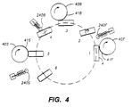
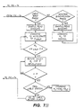
- FIG. 4 a process is shown for multiple labeling of rectangular containers.
- the process for labeling rectangular containers is analogous to the process illustrated in FIG. 3 for cylindrical containers but more movements of the container between stations may be required.
- FIG. 4 a front, back, and side labeling operation is shown in which a container 1 has a front label 41F applied to it by a vacuum drum 40F, container 3 has a back label 41B applied to it by a vacuum drum 40B, and container 5 has a side label 41S applied to it by a vacuum drum 40S.
- Containers 2 and 4 represent containers at intermediate points between labeling operations.
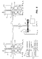
- a central turret shaft 11 is provided to turn a turret plate 13.
- the turret shaft 11 is driven by a motor 25.
- a drive shaft 26 extends from the motor 25 and is utilized to drive turret shaft 11.
- the portion of the labeling apparatus containing the motor 25, motor gear 27 and front gear 28, and related components is in the drive motor housing 60. It is separated by a partition 61 from the turret plate 13 and container handling stations 24.
- a turret shaft sensor 31 Also located in the drive motor housing 60 is a turret shaft sensor 31. As the turret shaft 11 rotates, the motion of the turret shaft 11 is transferred from turret gear 28 to sensor gear 29. This motion is sensed by sensor 31. The sensor 31 generates a plurality of electrical signals representative of the direction, speed and angular position of the turret shaft 11 in response to the sensed motion and position of shaft 30. For some sensors, the electrical signals generated are pulses which may be coded to represent the direction, speed, and angular position of the shaft. This signal is propagated across control lines 22 and 21 to the computer 20.
- An electrical signal propagating station 23 is mounted on top of the turret plate 13 about drive shaft 11. This station 23 permits continuous electrical signal propagation between lines running from the computer 20 to rotating stations 24 and vice versa. Methods and apparatus for providing the electrical signal propagating station 23 are generally known in the art.
- a general purpose computer of the type referred to as an IBM compatible computer having sufficient processor speed may be configured with appropriate interfaces to sense and control the labeling apparatus.
- Methods of control are known in the art and are taught in standard reference texts such as Incremental Motor Control - Volume I - DC Motors and Control Systems edited by Benjamin C. Kuo and Jacob Tal, published by the SRL Publishing Co.
- the additional output diver is required only when the required motor exciting signal has a larger voltage or current than is possible or desirable to provide directly from the output interface 105, or where the control signal may more effectively be generated external to the computer or its interface.
- the output driver 106 may be an amplifier, or may be a voltage controlled oscillator which generates a variable frequency pulse signal for a stepper motor.
- the output motor signals are analog signals less than a few amperes and fewer than 10 volts; however, motors requiring larger voltage or current signals may be used.
- the ability to continuously steer the container also permits reorientation of the container for a subsequent labeling operation on a different face. For example, in FIG. 4, container 2 is being rotated clockwise so as to present the appropriate face for labeling at vacuum drum 40B.
- the steering also permits a pressure device such as spring loaded roller 240B that is illustrated at position 4 to be used to urge the adhesive covered label onto the surface of the container.
- a pressure device such as spring loaded roller 240B that is illustrated at position 4 to be used to urge the adhesive covered label onto the surface of the container.
- the orientation of the container may be adjusted as the container passes the pressure application station 240B so that a relatively constant pressure is maintained.
- Other pressure devices such as a linear wiper arm, a brush, or a stream of directed compressed air may also be used to urge the label to contact the surface of the container.
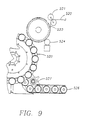
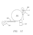
- the turret picks up each container in its turn, spins it and transports it past the vacuum drum 523, where it contacts the leading end of a label on the vacuum drum.
- the vacuum is released at this point of contact so that the label is released and will adhere to and wrap around the container.
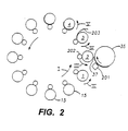
- FIG. 14 having spherical bodies.
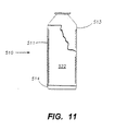
- the invention is also applicable to articles such as, for example, a cylindrical bottle or other container having on its cylindrical surface projecting portions to serve as decoration and which stand out from the cylindrical surface.
- the elastic segments for example, transparent stretchable label material, may be applied over such projecting portions and onto the cylindrical body of the bottle.
- the article may have a decorative projection.
- a transparent elastic label may be wrapped around the container in stretched position so as to overlie but not conceal the projecting decoration. The applied label will shrink onto the surrounding cylindrical surface.
- FIG. 17 shows a bottle 40 and cap 42 with a label 44 adhesively secured thereto.
- Label 44 has an indicia pattern 46 thereon, again including an arrangement of ridges 50.
- a label 52 can be applied to the top or side of a beverage can 54.
- Label 52 contains tactilely ascertainable information, such as in the form of ridges 56 arranged in a braille configuration.
- a cutter assembly 164 located adjacent roller 152, cuts appropriately sized labels 166 from stock 90.
- Roller 152 is a vacuum drum which applies a vacuum to hold stock 90 thereagainst while label 166 is cut.
- Each individual label 166 carries the embossed braille pattern thereon.
- the cutter assembly 164 and die insert 156 are in registry with one another as die rollers 152 and 154 are rotated so that the braille pattern and any printed matter on labels 166 are appropriately located relative to the leading and trailing edge portions on labels 166.
- FIG. 25 shows rollers 152 and 154 in perspective embossing a label 90 passing therebetween.
- Glue spit gun 246 includes a supply conduit 254 and a drain conduit 256.
- a reservoir 260 holds molten glue therein under pressure.
- Nozzles 262 spray droplets 248 onto label 244.
- a computer controller 270 controls the timing and pattern of the sputtering of the glue droplets from spit gun 246 onto labels 244.
- the Nordson Controlled Fiberization System 272 would replace the glue wheel 202 and spit gun 246 of FIGs. 26 and 27.
- the Nordson Controlled Fiberization System emits droplets of glue unto the backside of label 244, held by the vacuum drum 242.
Landscapes
- Labeling Devices (AREA)
- Road Signs Or Road Markings (AREA)
- Illuminated Signs And Luminous Advertising (AREA)
- Printers Characterized By Their Purpose (AREA)
Claims (7)
- Verfahren zum Aufbringen eines elastischen Abschnitts aus Blattmaterial, das ein Vorderende (37) und ein an dem Vorderende (37) nicht angebrachtes Hinterende aufweist, auf der Oberfläche eines Gegenstands (3), der eine Zone maximalen Durchmessers und zumindest einen benachbarten Bereich kleineren Durchmessers aufweist, wobei das Verfahren umfasst: Aufbringen des Abschnitts an dem Gegenstand (3) so, dass er auf der Zone maximalen Durchmessers und dem zumindest einen benachbarten Bereich aufliegt, durch Kleben des Vorderendes (37) des Abschnitts auf den Gegenstand (3), Wickeln des Abschnitts um den Gegenstand herum, sodass er auf der Zone und dem zumindest einen benachbarten Bereich aufliegt, und Sichern des Hinterendes des Abschnitts an dem Vorderende (37) oder an dem Gegenstand (3), dadurch gekennzeichnet, dass das Verfahren umfasst, vor dem Aufbringen des Abschnitts auf den Gegenstand (3) so, dass er auf der Zone maximalen Durchmessers und dem zumindest einen benachbarten Bereich aufliegt, ein computergesteuertes System zum Anlegen einer Zugkraft zu verwenden, ausgeübt durch eine Technik, entweder die Umfangsgeschwindigkeit einer drehbaren Vakuumtrommel (35), so zu steuern/zu regeln, dass sie größer ist als die der Abschnittszuführung, oder zu bewirken, dass der Gegenstand mit einer Umfangsgeschwindigkeit umläuft, die größer ist als jene einer drehbaren Vakuumtrommel, um hierdurch den Abstand zwischen dem Vorderende (37) und dem Hinterende zu vergrößern und hierdurch einen gereckten Abschnitt zu bilden, wobei das Recken ausreicht, sodass dann, wenn die angelegte Zugkraft von dem gereckten Abschnitt gelöst wird, der Abschnitt, der auf der Zone maximalen Durchmessers und dem zumindest einen benachbarten Bereich aufliegt, ausreichend eng und dicht an dem zumindest einen benachbarten Bereich anhaftet, wodurch der Abschnitt auf die Zone maximalen Durchmessers und den zumindest einen benachbarten Bereich kleineren Durchmessers der Oberfläche des Gegenstands (3) wärmeschrumpfbar ist.
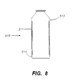
- Verfahren nach Anspruch 1, worin der Abschnitt ein Etikett (36) ist und der Gegenstand (3) ein Behälter (540) mit einem Körperabschnitt ist, wobei die Oberfläche des Körperabschnitts zwischen ihren Enden die Zone maximalen Durchmessers (543) und den zumindest einen benachbarten Bereich (542, 543) kleineren Durchmessers aufweist.
- Verfahren nach Anspruch 1 zum Etikettieren eines Gegenstands (3), dadurch gekennzeichnet, dass der Abschnitt des Blattmaterials ein Reck-Etikett (36) ist.
- Verfahren nach Anspruch 1 zum Aufbringen eines Reck-Etiketts (36) auf eine vorbestimmte Stelle auf der Oberfläche eines'Gegenstands (3), der eine beliebige Umfangsoberflächenform und eine Oberflächenumfangsdimension hat, die die Zone maximalen Durchmessers (543) und den zumindest einen benachbarten Bereich kleineren Durchmessers (541, 542) aufweist, unter Verwendung eines computergesteuerten Etikettierungssystems, wobei das System umfasst: einen Computer (20), Mittel zum Transportieren des Gegenstands, die eine Revolverplatte (13) und ein Spannfutter (14) zum Halten des Gegenstands (3) aufweisen, sowie Mittel (18, 31) zum Erfassen einer Winkelstellung, einer Drehrichtung und einer Geschwindigkeit der Revolverplatte (13) und des Spannfutters (14) und zum Transportieren des Gegenstands entlang einem festen Weg, der durch das Transportmittel definiert ist, sowie Mittel zum Aufbringen von Reck-Etiketten (36) auf die Gegenstände (3), die eine Schneidvorrichtung (521) zum Schneiden eines elastischen Abschnitts eines Blattmaterials von einer Materialrolle aufweist, wobei der Abschnitt ein Reck-Etikett ist, sowie die drehbare Vakuumtrommel (35) zum Halten des Etiketts, wobei das Verfahren umfasst:Vorsehen eines Reck-Etiketts (36), das eine ungereckte Länge hat, die kleiner ist als die Länge der Oberfläche des Gegenstands (3), der mit dem Etikett zu bedecken ist;Recken des Etiketts durch Anlegen der Zugkraft, um den Abstand zwischen den Vorder- und Hinterenden zu vergrößern, sodass die Länge des gereckten Etiketts größer oder gleich der Länge der mit dem Etikett abzudeckenden Oberfläche des Gegenstands (3) ist;Aufbringen des Etiketts, während es so gereckt ist, auf den Gegenstands, sodass es auf der Zone maximalen Durchmessers (543) und dem zumindest einen benachbarten Bereich aufliegt, durch Auftragen von Klebstoff auf das Vorderende (37), um hierdurch das Vorderende (37) des gereckten Etiketts auf den Gegenstand zu kleben, Wickeln des Etiketts, während es noch in dem gereckten Zustand ist, um den Gegenstand (3) herum, sodass es auf der Zone und dem zumindest einen benachbarten Bereich aufliegt, wobei der Klebstoff das Vorderende (37) an dem Gegenstand (3) im Wesentlichen sichert, bevor das Etikett von der Vakuumtrommel (35) gelöst wird, und Sichern des Hinterendes des gereckten Etiketts an dem Vorderende oder an dem Gegenstand (3) durch Auftragen von Klebstoff zum Ankleben des Hinterendes oder des unter dem Hinterende liegenden Bereichs, bevor sich das gereckte Etikett in Anpassung an den Gegenstand (3) entspannen gelassen wird; undSteuern/Regeln des Reckens und des Aufbringens des Etiketts durch:Auswählen einer Mehrzahl befohlener numerischer Werte umfassend, die einen befohlenen numerischen Wickelorientierungswert, einen befohlenen numerischen Drehrichtungswert und einen befohlenen numerischen Drehgeschwindigkeitswert für jeweils die drehbare Vakuumtrommel (35), die Revolverplatte (13) und das Spannfutter (14) sowie einen befohlenen numerischen Schneidvorrichtungstellungswert für die Schneidvorrichtung (54), wobei die Mehrzahl befohlener numerischer Werte in Kombination eine Mehrzahl räumlicher und zeitlicher Beziehungen zwischen und unter der Vakuumtrommel (35), der Revolverplatte (13), dem Spannfutter (14) und der Schneidvorrichtung (521) definieren, um das Etikett (36) auf den Gegenstand (3) an der vorbestimmten Stelle aufzubringen;mathematisches Charakterisieren der Mehrzahl räumlicher und zeitlicher Beziehungen zwischen der Mehrzahl numerischer Werte und der Mehrzahl räumlicher Charakteristika des Gegenstands (3) und des Etiketts (36), die enthalten: zumindest eine Umfangsdimension des Gegenstands (3), eine lineare Dimension entlang der Etikettenrichtung, die der Gegenstands (3)-Umfangsrichtung für das aufzubringende Etikett (36) entspricht, und eine Stelle auf dem Gegenstand (3), wo das Etikett (36) aufzubringen ist;Transportieren des Gegenstands (3) entlang dem Weg;Erfassen der Geschwindigkeit des Transportmittels;Berechnen in dem Computer (20) einer Mehrzahl berechneter numerischer Werte, umfassend einen berechneten numerischen Winkelorientierungswert, einen berechneten numerischen Drehungswert, einen berechneten numerischen Drehgeschwindigkeitswert für jeweils die drehbare Vakuumtrommel (35), die Revolverplatte (13) und das Spannfutter (14), sowie einen berechneten numerischen Schneidvorrichtungstellungswert, wobei die Mehrzahl berechneter numerischer Werte in Kombination, die die Mehrzahl zeitlicher und räumlicher Beziehungen zwischen der Trommel, der Revolverplatte (13), dem Spannfutter (14) und der Schneidvorrichtung (54) definieren, dafür sorgen, dass das Etikett (36) an der vorbestimmten Stelle auf den Gegenstand (3) aufgebracht wird; Erzeugen in dem Computer (20) einer Mehrzahl von Steuersignalen, wobei jedes Steuersignal jedem der Mehrzahl befohlener numerischer Werte entspricht, in Antwort auf die Mehrzahl berechneter numerischer Werte; undAnlegen der Mehrzahl von Steuersignalen an die Mittel zum Transportieren und an die Mittel zum Aufbringen von Reck-Etiketten (36), sodass das Etikett (36) um einen vorbestimmten Betrag gereckt wird, wenn es auf den Gegenstand (3) und an der vorbestimmten Stelle auf den Gegenstand (3) aufgebracht wird.
- Vorrichtung zum Aufbringen eines elastischen Abschnitts aus Blattmaterial, wobei der Abschnitt ein Vorderende (37) und ein an dem Vorderende (37) nicht angebrachtes Hinterende aufweist, auf der Oberfläche eines Gegenstands (3), der eine Zone maximalen Durchmessers und zumindest einen benachbarten Bereich kleineren Durchmessers aufweist, wobei die Vorrichtung Mittel umfasst, um den Abschnitt auf den Gegenstand (3) so aufzubringen, dass er auf der Zone maximalen Durchmessers und dem zumindest einen benachbarten Bereich aufliegt, durch Kleben des Vorderendes des Abschnitts auf den Gegenstand (3), Wickeln des Abschnitts um den Gegenstand, sodass er auf der Zone und dem zumindest einen benachbarten Bereich aufliegt, und Sichern des Hinterendes des Abschnitts an dem Vorderende (37) oder auf dem Gegenstand (3), dadurch gekennzeichnet, dass ein computergesteuertes System vorgesehen ist, um eine Zugkraft anzulegen, ausgeübt durch eine Technik, entweder die Umfangsgeschwindigkeit einer drehbaren Vakuumtrommel (35) so zu steuern/zu regeln, dass sie größer ist als die der Abschnittszuführung, oder zu bewirken, dass der Gegenstand mit einer Umfangsgeschwindigkeit umläuft, die größer ist als die einer drehbaren Vakuumtrommel, um hierdurch einen Abstand zwischen dem Vorderende (37) und dem Hinterende zu vergrößern und hierdurch einen gereckten Abschnitt zu bilden, sowie Mittel zum Lösen der Zugkraft von dem gereckten Abschnitt, um hierdurch den Abschnitt ausreichend eng an den zumindest einen benachbarten Bereich anzuheften, wodurch der Abschnitt auf die Zone maximalen Durchmessers und den zumindest einen benachbarten Bereich kleineren Durchmessers der Oberfläche des Gegenstands (3) wärmeschrumpfbar ist.
- Vorrichtung nach Anspruch 5, dadurch gekennzeichnet, dass die Mittel zum Recken und die Mittel zum Anlegen gemeinsam ein computergesteuertes Etikettierungssystem aufweisen, wobei das System umfasst:einen Computer (20);Mittel zum Erfassen einer Winkelstellung, einer Drehrichtung und einer Geschwindigkeit einer Revolverplatte (13) und eines Spannfutters (14) und zum Transportieren des Gegenstands (3) entlang einem festen Weg, der durch das Transportmittel definiert ist; undMittel zum Aufbringen des elastischen Abschnitts auf den Gegenstand (3), umfassend eine Schneidvorrichtung (521) zum Schneiden des elastischen Abschnitts aus Blattmaterial von einer Materialrolle, sowie die drehbare Vakuumtrommel (35) zum Halten des Abschnitts.
- Vorrichtung nach Anspruch 6, dadurch gekennzeichnet, dass das System umfasst:wobei die Mehrzahl befohlener numerischer Werte in Kombination eine Mehrzahl befohlener räumlicher und zeitlicher Beziehungen zwischen und unter der Vakuumtrommel, der Revolverplatte, dem Spannfutter und der Schneidvorrichtung definieren, um den Abschnitt an der vorbestimmten Stelle auf den Gegenstand aufzubringen;Mittel zum Wählen einer Mehrzahl befohlener numerischer Werte, umfassend:einen befohlenen numerischen Winkelorientierungswert für jeweils die drehbare Vakuumtrommel (35), die Revolverplatte (13) und das Spannfutter (14),einen befohlenen numerischen Drehrichtungswert für jeweils die drehbare Vakuumtrommel, die Revolverplatte und das Spannfutter; undeinen befohlenen numerischen Drehgeschwindigkeitswert für jeweils die drehbare Vakuumtrommel, die Revolverplatte und das Spannfutter, undeinen befohlenen Schneidvorrichtungstellungswert für die Schneidvorrichtung (52),
Mittel zum mathematischen Charakterisieren einer Mehrzahl tatsächlicher räumlicher und zeitlicher Beziehungen zwischen und unter der Vakuumtrommel, der Revolverplatte, dem Spannfutter und der Schneidvorrichtung, sowie einer Mehrzahl tatsächlicher räumlicher Charakteristika zwischen dem Gegenstand und dem Abschnitt, die zumindest eine Umfangsdimension des Gegenstands zum Definieren einer Schnittlänge des Abschnitts und eine Stelle des Gegenstands zum Anordnen des Abschnitts umfassen;
Mittel zum Erfassen der Geschwindigkeit des Transportmittels;
Mittel zum Berechnen einer Mehrzahl berechneter numerischer Werte, umfassend:wobei die Mehrzahl berechneter numerischer Werte in Kombination eine Mehrzahl berechneter räumlicher und zeitlicher Beziehungen zwischen und unter der Vakuumtrommel, der Revolverplatte, dem Spannfutter und der Schneidvorrichtung definieren, um den Abschnitt an der vorbestimmten Stelle auf den Gegenstand aufzubringen;einen berechneten Winkelorientierungswert für jeweils die drehbare Vakuumtrommel, die Revolverplatte und das Spannfutter,einen berechneten numerischen Drehungswert für jeweils die drehbare Vakuumtrommel, die Revolverplatte und das Spannfutter,einen berechneten numerischen Drehgeschwindigkeitswert für jeweils die drehbare Vakuumtrommel, die Revolverplatte und das Spannfutter sowie einen berechneten Schneidvorrichtungstellungswert für die Schneidvorrichtung,
Mittel zum Erzeugen in dem Computer (20) einer Mehrzahl von Steuersignalen, wobei jedes Steuersignal jedem der befohlenen numerischen Werte entspricht, in Antwort auf jeden der berechneten numerischen Werte; und
Mittel zum Anlegen der Mehrzahl von Steuersignalen an das Transportmittel und an das Abschnittaufbringemittel, um hierdurch den Abschnitt um einen vorbestimmten Betrag zu recken, während der Abschnitt an der vorbestimmten Stelle auf dem Gegenstand aufgebracht wird.
Priority Applications (1)
| Application Number | Priority Date | Filing Date | Title |
|---|---|---|---|
| EP01103055A EP1122173B1 (de) | 1995-06-07 | 1996-06-07 | Verfahren und Vorrichtung zum Anbringen von Etiketten in Blindenschrift auf Gegenständen |
Applications Claiming Priority (3)
| Application Number | Priority Date | Filing Date | Title |
|---|---|---|---|
| US48415495A | 1995-06-07 | 1995-06-07 | |
| US484154 | 1995-06-07 | ||
| PCT/US1996/009392 WO1996040559A2 (en) | 1995-06-07 | 1996-06-07 | Computer controlled labeling machine |
Related Child Applications (1)
| Application Number | Title | Priority Date | Filing Date |
|---|---|---|---|
| EP01103055A Division EP1122173B1 (de) | 1995-06-07 | 1996-06-07 | Verfahren und Vorrichtung zum Anbringen von Etiketten in Blindenschrift auf Gegenständen |
Publications (3)
| Publication Number | Publication Date |
|---|---|
| EP0885144A2 EP0885144A2 (de) | 1998-12-23 |
| EP0885144A4 EP0885144A4 (de) | 2000-03-08 |
| EP0885144B1 true EP0885144B1 (de) | 2003-10-22 |
Family
ID=23922979
Family Applications (2)
| Application Number | Title | Priority Date | Filing Date |
|---|---|---|---|
| EP96923231A Expired - Lifetime EP0885144B1 (de) | 1995-06-07 | 1996-06-07 | Verfahren und computergesteuerte maschine zum anbringen reckbarer etikette auf gegenständen |
| EP01103055A Expired - Lifetime EP1122173B1 (de) | 1995-06-07 | 1996-06-07 | Verfahren und Vorrichtung zum Anbringen von Etiketten in Blindenschrift auf Gegenständen |
Family Applications After (1)
| Application Number | Title | Priority Date | Filing Date |
|---|---|---|---|
| EP01103055A Expired - Lifetime EP1122173B1 (de) | 1995-06-07 | 1996-06-07 | Verfahren und Vorrichtung zum Anbringen von Etiketten in Blindenschrift auf Gegenständen |
Country Status (11)
| Country | Link |
|---|---|
| US (2) | US6287671B1 (de) |
| EP (2) | EP0885144B1 (de) |
| JP (1) | JPH11507312A (de) |
| KR (1) | KR100372400B1 (de) |
| AT (2) | ATE252488T1 (de) |
| AU (1) | AU718257B2 (de) |
| BR (1) | BR9609108A (de) |
| CA (1) | CA2223946C (de) |
| DE (2) | DE69632211T2 (de) |
| TW (1) | TW340826B (de) |
| WO (1) | WO1996040559A2 (de) |
Families Citing this family (90)
| Publication number | Priority date | Publication date | Assignee | Title |
|---|---|---|---|---|
| JPH11507312A (ja) * | 1995-06-07 | 1999-06-29 | ビー アンド エイチ マニュファクチュアリング カンパニー インコーポレイテッド | 触知可能なしるしと伸びるラベルを含むラベルを物品に付けるためのコンピュータ制御式ラベリングマシン |
| KR100415059B1 (ko) * | 1995-06-28 | 2004-02-18 | 비 앤드 에이치 매뉴팩춰링 컴파니, 인코포레이티드 | 시트재료의탄성세그먼트를부착하는방법 |
| EP0806364A1 (de) * | 1996-05-07 | 1997-11-12 | M & W Verpackungen Mildenberger & Willing GmbH | Verfahren zum Wrap-around-Etikettieren von Behältern |
| US6501390B1 (en) * | 1999-01-11 | 2002-12-31 | International Business Machines Corporation | Method and apparatus for securely determining aspects of the history of a good |
| US6428639B1 (en) | 1999-07-19 | 2002-08-06 | Krones, Inc. | Computer controlled position slaved servo labeling system |
| US6984429B2 (en) * | 2001-01-12 | 2006-01-10 | 3M Innovative Properties Company | Laminate from which decorative films can be applied to a substrate |
| US20030069977A1 (en) * | 2001-10-09 | 2003-04-10 | Pitney Bowes Incorporated | Method and system for identifying and providing additional information about an article to the visually impaired |
| US7090907B2 (en) | 2002-06-18 | 2006-08-15 | Spear Usa, Llc | Adhesive coated label having tactile feel |
| JP2006510058A (ja) | 2002-12-13 | 2006-03-23 | スピア ユー.エス.エー., エル.エル.シー. | 改良された美的外観を有するラベル |
| US7207467B1 (en) | 2003-03-19 | 2007-04-24 | Arjuna Raja | Identifying devices for the visually handicapped |
| ITMN20030036A1 (it) * | 2003-08-08 | 2005-02-09 | Global Packaging Solutions S R L | Macchina etichettatrice |
| DE502004007456D1 (de) * | 2004-01-19 | 2008-08-07 | Krones Ag | Vorrichtung zum bewegen und etikettieren von behältern |
| DE202004013947U1 (de) * | 2004-09-08 | 2005-02-17 | Krones Ag | Artikel mit einer etikettierten Mantelfläche und Vorrichtung zum Etikettieren eines Artikels |
| USD531047S1 (en) * | 2004-09-17 | 2006-10-31 | Unilever Bestfoods, North America Division Of Conopco, Inc. | Container |
| US7307249B2 (en) * | 2004-09-30 | 2007-12-11 | Cantu Homaro R | System and methods for preparing substitute food items |
| JP2006116823A (ja) * | 2004-10-21 | 2006-05-11 | Seiko Epson Corp | テープカートリッジおよびこれが着脱自在に装着されるテープ処理装置 |
| DE102004055745A1 (de) * | 2004-11-18 | 2006-06-01 | Krones Ag | Drehwertgeber und Rundläufermaschine |
| GB0501369D0 (en) * | 2005-01-22 | 2005-03-02 | Stepping Stones Invest Ltd | Improvements to labels and application apparatus therefor |
| US20060118507A1 (en) * | 2005-03-07 | 2006-06-08 | Feldman Brenda L | Device and method for identifying containers personal to sighted and visually handicapped individuals |
| DE102005023983B4 (de) * | 2005-05-20 | 2007-04-12 | Khs Ag | Etikettiermaschine für Behälter |
| US7704347B2 (en) | 2005-05-27 | 2010-04-27 | Prairie Packaging, Inc. | Reinforced plastic foam cup, method of and apparatus for manufacturing same |
| US7814647B2 (en) | 2005-05-27 | 2010-10-19 | Prairie Packaging, Inc. | Reinforced plastic foam cup, method of and apparatus for manufacturing same |
| US7536767B2 (en) | 2005-05-27 | 2009-05-26 | Prairie Packaging, Inc. | Method of manufacturing a reinforced plastic foam cup |
| US7694843B2 (en) | 2005-05-27 | 2010-04-13 | Prairie Packaging, Inc. | Reinforced plastic foam cup, method of and apparatus for manufacturing same |
| US7552841B2 (en) | 2005-05-27 | 2009-06-30 | Prairie Packaging, Inc. | Reinforced plastic foam cup, method of and apparatus for manufacturing same |
| US7818866B2 (en) | 2005-05-27 | 2010-10-26 | Prairie Packaging, Inc. | Method of reinforcing a plastic foam cup |
| DE102005041531A1 (de) * | 2005-08-31 | 2007-03-01 | Krones Ag | Positionsveränderbare Steuerkonsole |
| US20070175574A1 (en) * | 2006-01-27 | 2007-08-02 | Douglas Crank | Apparatus and method for conforming a label to the contour of a container |
| AU2007236395A1 (en) * | 2006-04-10 | 2007-10-18 | Dietmar Basta | Portable diagnostic system for a balancing function |
| ATE555991T1 (de) | 2006-06-06 | 2012-05-15 | Sidel Holdings & Technology Sa | Rotierende etikettiermaschine |
| KR101162261B1 (ko) * | 2006-12-15 | 2012-07-04 | 씨씨엘 라벨 게엠베하 | 신축성있는 필름 소재로 된 슬리브 라벨용 부착장치 |
| US9010567B2 (en) * | 2006-12-15 | 2015-04-21 | Theresa Pink | Lid |
| KR100853027B1 (ko) * | 2007-04-19 | 2008-08-20 | 씨아이에스(주) | 이차전지용 전극의 자동 라벨링 장치 |
| DE202008004480U1 (de) * | 2008-04-02 | 2009-08-13 | Krones Ag | Halteeinrichtung für Drehimpulsgeber |
| KR101008823B1 (ko) | 2008-09-18 | 2011-01-19 | 씨브이씨 테크놀로지스 인코포레이티드 | 설명서 부착 장치 |
| US8944823B2 (en) * | 2009-02-06 | 2015-02-03 | George Kasboske | Product identification system for persons with limited vision |
| DE102009034217A1 (de) * | 2009-07-22 | 2011-01-27 | Krones Ag | Steuerung von Drehtellern in Etikettiermaschinen |
| KR101129052B1 (ko) | 2010-02-08 | 2012-03-23 | 위더스케미칼 주식회사 | 용기 라벨링용 라벨 접착장치 |
| US8828170B2 (en) | 2010-03-04 | 2014-09-09 | Pactiv LLC | Apparatus and method for manufacturing reinforced containers |
| US8864707B1 (en) | 2010-12-03 | 2014-10-21 | Medical Device Engineering, LLC. | Tamper indicating closure assembly |
| DE102011087729A1 (de) * | 2011-12-05 | 2013-06-06 | Krones Ag | Vorrichtung und Verfahren zum Etikettieren von Behältern mit elastischen Etikettenhülsen |
| DE102011087728A1 (de) * | 2011-12-05 | 2013-06-06 | Krones Ag | Verfahren und Vorrichtung zum Etikettieren von Behältern mit Etikettenhülsen |
| KR101270946B1 (ko) | 2011-12-16 | 2013-06-11 | 주식회사 비에스테크 | 안테나 기능을 구비하는 휴대용 단말기 커버 제조 방법 |
| DE102012003354A1 (de) * | 2012-02-21 | 2013-08-22 | Khs Gmbh | Verfahren zum Etikettieren von Behältern sowie Etikettiermaschine |
| JP2013199079A (ja) * | 2012-03-26 | 2013-10-03 | Heishin Engineering & Equipment Co Ltd | 触知プリンター |
| JP5505669B1 (ja) * | 2012-12-17 | 2014-05-28 | 東洋製罐株式会社 | 自転駆動機構および該機構を用いたフィルムラベル貼着装置 |
| DE102013204461A1 (de) * | 2013-03-14 | 2014-09-18 | Krones Ag | Rundläufermaschine mit einem Karussell und Verfahren für eine Rundläufermaschine |
| GB2519372B (en) * | 2013-10-21 | 2020-06-03 | Videojet Technologies Inc | Machine and method of operation |
| US10912898B1 (en) | 2014-02-03 | 2021-02-09 | Medical Device Engineering Llc | Tamper evident cap for medical fitting |
| US10207099B1 (en) | 2014-02-21 | 2019-02-19 | Patrick Vitello | Closure assembly for medical fitting |
| US9828158B2 (en) * | 2014-04-03 | 2017-11-28 | Toyota Motor Engineering & Manufacturing North America, Inc. | Packaging for visually impaired and blind persons |
| DE102014105485A1 (de) * | 2014-04-17 | 2015-10-22 | Krones Ag | Vorrichtung und Verfahren zum Ausstatten von Behältern mit beleimten Etiketten |
| US10300263B1 (en) | 2015-02-27 | 2019-05-28 | Timothy Brandon Hunt | Closure assembly for a medical connector |
| US10166343B1 (en) | 2015-03-13 | 2019-01-01 | Timothy Brandon Hunt | Noise evident tamper cap |
| US10315024B1 (en) | 2015-03-19 | 2019-06-11 | Patick Vitello | Torque limiting closure assembly |
| DE202015104055U1 (de) * | 2015-08-03 | 2016-11-04 | Haendler & Natermann Gmbh | Behälter-Nassleimetikett, Prägewerkzeug für ein Behälter-Nassleimetikett und Behälter oder Flasche mit einem Behälter-Nassleimetikett |
| US11069263B2 (en) * | 2016-11-03 | 2021-07-20 | Jakayla Dixon | Systems and methods for identifying articles of clothing |
| US11097071B1 (en) | 2016-12-14 | 2021-08-24 | International Medical Industries Inc. | Tamper evident assembly |
| US10307548B1 (en) * | 2016-12-14 | 2019-06-04 | Timothy Brandon Hunt | Tracking system and method for medical devices |
| US10953162B1 (en) | 2016-12-28 | 2021-03-23 | Timothy Brandon Hunt | Tamper evident closure assembly |
| US10758684B1 (en) | 2017-03-03 | 2020-09-01 | Jonathan J. Vitello | Tamper evident assembly |
| US11040149B1 (en) | 2017-03-30 | 2021-06-22 | International Medical Industries | Tamper evident closure assembly for a medical device |
| US10888672B1 (en) | 2017-04-06 | 2021-01-12 | International Medical Industries, Inc. | Tamper evident closure assembly for a medical device |
| US10933202B1 (en) | 2017-05-19 | 2021-03-02 | International Medical Industries Inc. | Indicator member of low strength resistance for a tamper evident closure |
| US10898659B1 (en) | 2017-05-19 | 2021-01-26 | International Medical Industries Inc. | System for handling and dispensing a plurality of products |
| US10682837B2 (en) | 2017-06-09 | 2020-06-16 | The Proctor & Gamble Company | Method and compositions for applying a material onto articles |
| US11541180B1 (en) | 2017-12-21 | 2023-01-03 | Patrick Vitello | Closure assembly having a snap-fit construction |
| US11278681B1 (en) | 2018-02-20 | 2022-03-22 | Robert Banik | Tamper evident adaptor closure |
| US11413406B1 (en) | 2018-03-05 | 2022-08-16 | Jonathan J. Vitello | Tamper evident assembly |
| US11857751B1 (en) | 2018-07-02 | 2024-01-02 | International Medical Industries Inc. | Assembly for a medical connector |
| US11793987B1 (en) | 2018-07-02 | 2023-10-24 | Patrick Vitello | Flex tec closure assembly for a medical dispenser |
| US11779520B1 (en) | 2018-07-02 | 2023-10-10 | Patrick Vitello | Closure for a medical dispenser including a one-piece tip cap |
| CN108750260B (zh) * | 2018-07-03 | 2024-02-06 | 河南中包科技有限公司 | 一种用于啤酒贴标机标签喷胶装置 |
| US11690994B1 (en) | 2018-07-13 | 2023-07-04 | Robert Banik | Modular medical connector |
| US11426328B1 (en) | 2018-08-31 | 2022-08-30 | Alexander Ollmann | Closure for a medical container |
| US11471610B1 (en) | 2018-10-18 | 2022-10-18 | Robert Banik | Asymmetrical closure for a medical device |
| USD948713S1 (en) | 2019-09-03 | 2022-04-12 | International Medical Industries, Inc. | Asymmetrical self righting tip cap |
| USD903865S1 (en) | 2018-11-19 | 2020-12-01 | International Medical Industries, Inc. | Self-righting tip cap |
| FR3090456B1 (fr) | 2018-12-19 | 2020-11-27 | Sidel Participations | Ligne de production de récipients controlée par un dispositif de détermination de position |
| US11911339B1 (en) | 2019-08-15 | 2024-02-27 | Peter Lehel | Universal additive port cap |
| US11697527B1 (en) | 2019-09-11 | 2023-07-11 | Logan Hendren | Tamper evident closure assembly |
| US11357588B1 (en) | 2019-11-25 | 2022-06-14 | Patrick Vitello | Needle packaging and disposal assembly |
| US11904149B1 (en) | 2020-02-18 | 2024-02-20 | Jonathan Vitello | Oral tamper evident closure with retained indicator |
| US11523970B1 (en) | 2020-08-28 | 2022-12-13 | Jonathan Vitello | Tamper evident shield |
| US12070591B1 (en) | 2020-12-14 | 2024-08-27 | Patrick Vitello | Snap action tamper evident closure assembly |
| US11872187B1 (en) | 2020-12-28 | 2024-01-16 | Jonathan Vitello | Tamper evident seal for a vial cover |
| US12172803B1 (en) | 2021-10-04 | 2024-12-24 | Patrick Vitello | Tamper evident integrated closure |
| US12545483B1 (en) | 2022-04-22 | 2026-02-10 | Medical Device Engineering, Llc | Systems and methods for filling and venting dropper bottles |
| DE102022123015A1 (de) * | 2022-09-09 | 2024-03-14 | Krones Aktiengesellschaft | Verfahren und Vorrichtung zum Etikettieren von Behältern |
| DE102024119045A1 (de) | 2024-07-04 | 2026-01-08 | Krones Aktiengesellschaft | Etikettiermaschine zum Etikettieren von Behältern |
Citations (2)
| Publication number | Priority date | Publication date | Assignee | Title |
|---|---|---|---|---|
| US5240335A (en) * | 1991-05-09 | 1993-08-31 | Eastman Kodak Company | Braille printing apparatus |
| US5251758A (en) * | 1991-07-15 | 1993-10-12 | Liblan & Co., Ltd. | Food container with grippable portion having sense of touch indicia |
Family Cites Families (32)
| Publication number | Priority date | Publication date | Assignee | Title |
|---|---|---|---|---|
| US3235433A (en) * | 1962-05-15 | 1966-02-15 | Reynolds Metals Co | Method and apparatus for applying labels to containers |
| USRE28732E (en) * | 1966-01-28 | 1976-03-09 | Njm, Inc. | Method of and apparatus for printing and feeding labels in a continuous web, and for verifying and cutting individual labels therefrom for application to articles |
| FR1568638A (de) * | 1967-06-13 | 1969-05-23 | ||
| US3834963A (en) | 1970-01-23 | 1974-09-10 | B & J Mfg Co | Method for applying labels to containers |
| US4108710A (en) | 1972-02-14 | 1978-08-22 | B & H Manufacturing Company, Inc. | Apparatus for applying labels to containers |
| US4108709A (en) | 1976-06-14 | 1978-08-22 | B & H Manufacturing Company, Inc. | Label applying machine |
| US4500386A (en) | 1977-03-31 | 1985-02-19 | B & H Manufacturing Company, Inc. | Container feed for labeling machine |
| US4181555A (en) | 1978-02-07 | 1980-01-01 | B & H Manufacturing Company, Inc. | Labeling apparatus and method for continuously severing labels from continuous label stock and applying the severed labels to containers |
| US4216044A (en) * | 1978-07-07 | 1980-08-05 | American Can Company | Method for applying a decoration to a cylindrical body |
| US4242167A (en) | 1978-10-26 | 1980-12-30 | B & H Manufacturing Company, Inc. | Labeling machine |
| IT1136172B (it) * | 1980-04-09 | 1986-08-27 | Cir Spa Divisione Sasib | Dispositivo a regolazione elettronica per il taglio progressivo in foglietti di una bobina di nastro di materilae in foglio anche stampato |
| US4704173A (en) | 1982-05-27 | 1987-11-03 | Wolfgang Hoffman | System for applying heat shrink film to containers and other articles and heat shrinking the same |
| US4416714A (en) * | 1982-05-27 | 1983-11-22 | B & H Manufacturing Company, Inc. | Labeling machine for heat shrink labels |
| US4749426A (en) * | 1984-02-22 | 1988-06-07 | Avery International Corporation | Silk screen roller applicator technique |
| US4762229A (en) * | 1987-07-02 | 1988-08-09 | Monica Wickre | Method and apparatus for orienting or labeling a beverage dispensing container responsive to tactile stimuli |
| US4923557A (en) * | 1988-08-01 | 1990-05-08 | Trine Manufacturing Co., Inc. | Apparatus and method for applying a heat shrink film to a container |
| US4978416A (en) | 1988-10-28 | 1990-12-18 | B & H Manufacturing Company, Inc. | Stack fed labeling machine |
| US5137596A (en) | 1990-01-12 | 1992-08-11 | B & H Manufacturing Company, Inc. | Apparatus for heat sealing labels on containers |
| US5011032A (en) * | 1990-02-28 | 1991-04-30 | Rollman Bruce L | Patient dosage regimen compliance bottle cap |
| US5269864A (en) | 1990-04-04 | 1993-12-14 | B & H Manufacturing Co., Inc. | High speed labeling machine |
| US5091040A (en) | 1990-05-03 | 1992-02-25 | B & H Manufacturing Co., Inc. | Turret type labeling machine with contoured vacuum drum |
| DE9016591U1 (de) | 1990-12-06 | 1991-02-21 | Krones Ag Hermann Kronseder Maschinenfabrik, 8402 Neutraubling | Vorrichtung zum Ausstatten von Gefäßen mit Etiketten |
| IL106069A0 (en) * | 1992-06-25 | 1993-10-20 | Ontario Ltd 498775 | Silk screen tactile prints and process |
| US5403416A (en) * | 1992-12-18 | 1995-04-04 | B & H Manufacturing Co., Inc. | Method of labeling containers with convex surfaces |
| US5413651A (en) * | 1993-03-23 | 1995-05-09 | B&H Manufacturing Company | Universal roll-fed label cutter |
| US5380381A (en) | 1993-06-03 | 1995-01-10 | B & H Manufacturing Company, Inc. | Labeling machine with variable speed cutting head |
| US5858143A (en) * | 1993-09-16 | 1999-01-12 | B & H Manufacturing, Inc. | Computer controlled labeling machine for applying labels including stretch labels and tactilely sensible indicia on articles |
| US5779482A (en) * | 1994-01-12 | 1998-07-14 | Yuugenkaisha Mediamews | Indications for the visually handicapped using transparent three-dimensional ink |
| US5649480A (en) * | 1995-06-07 | 1997-07-22 | Yim; Joan Marilyn | Touch-readable product and associated process |
| JPH11507312A (ja) * | 1995-06-07 | 1999-06-29 | ビー アンド エイチ マニュファクチュアリング カンパニー インコーポレイテッド | 触知可能なしるしと伸びるラベルを含むラベルを物品に付けるためのコンピュータ制御式ラベリングマシン |
| US5702559A (en) * | 1995-07-13 | 1997-12-30 | B&H Manufacturing Company, Inc. | Method and apparatus for applying a tactilely distinguishable marking on an article |
| US11607720B2 (en) | 2021-03-25 | 2023-03-21 | Bnsf Railway Company | Wedge driver and method therefor |
-
1996
- 1996-06-07 JP JP9501720A patent/JPH11507312A/ja not_active Ceased
- 1996-06-07 EP EP96923231A patent/EP0885144B1/de not_active Expired - Lifetime
- 1996-06-07 AU AU63799/96A patent/AU718257B2/en not_active Ceased
- 1996-06-07 KR KR1019970709292A patent/KR100372400B1/ko not_active Expired - Fee Related
- 1996-06-07 EP EP01103055A patent/EP1122173B1/de not_active Expired - Lifetime
- 1996-06-07 AT AT96923231T patent/ATE252488T1/de not_active IP Right Cessation
- 1996-06-07 DE DE69632211T patent/DE69632211T2/de not_active Expired - Fee Related
- 1996-06-07 AT AT01103055T patent/ATE264225T1/de not_active IP Right Cessation
- 1996-06-07 WO PCT/US1996/009392 patent/WO1996040559A2/en not_active Ceased
- 1996-06-07 CA CA002223946A patent/CA2223946C/en not_active Expired - Fee Related
- 1996-06-07 BR BR9609108A patent/BR9609108A/pt not_active IP Right Cessation
- 1996-06-07 DE DE69630469T patent/DE69630469T2/de not_active Expired - Fee Related
- 1996-07-05 TW TW085108137A patent/TW340826B/zh active
-
1999
- 1999-01-12 US US09/229,504 patent/US6287671B1/en not_active Expired - Lifetime
-
2001
- 2001-04-04 US US09/826,469 patent/US6488794B1/en not_active Expired - Fee Related
Patent Citations (2)
| Publication number | Priority date | Publication date | Assignee | Title |
|---|---|---|---|---|
| US5240335A (en) * | 1991-05-09 | 1993-08-31 | Eastman Kodak Company | Braille printing apparatus |
| US5251758A (en) * | 1991-07-15 | 1993-10-12 | Liblan & Co., Ltd. | Food container with grippable portion having sense of touch indicia |
Also Published As
| Publication number | Publication date |
|---|---|
| KR100372400B1 (ko) | 2003-06-18 |
| US6488794B1 (en) | 2002-12-03 |
| EP0885144A4 (de) | 2000-03-08 |
| DE69630469T2 (de) | 2004-07-29 |
| WO1996040559A3 (en) | 1997-04-10 |
| DE69630469D1 (de) | 2003-11-27 |
| CA2223946A1 (en) | 1996-12-19 |
| US6287671B1 (en) | 2001-09-11 |
| AU718257B2 (en) | 2000-04-13 |
| ATE264225T1 (de) | 2004-04-15 |
| KR19990022823A (ko) | 1999-03-25 |
| EP1122173A2 (de) | 2001-08-08 |
| EP1122173A3 (de) | 2003-01-02 |
| ATE252488T1 (de) | 2003-11-15 |
| AU6379996A (en) | 1996-12-30 |
| EP0885144A2 (de) | 1998-12-23 |
| JPH11507312A (ja) | 1999-06-29 |
| CA2223946C (en) | 2002-09-10 |
| BR9609108A (pt) | 1999-06-15 |
| EP1122173B1 (de) | 2004-04-14 |
| DE69632211T2 (de) | 2005-04-14 |
| TW340826B (en) | 1998-09-21 |
| WO1996040559A2 (en) | 1996-12-19 |
| DE69632211D1 (de) | 2004-05-19 |
Similar Documents
| Publication | Publication Date | Title |
|---|---|---|
| EP0885144B1 (de) | Verfahren und computergesteuerte maschine zum anbringen reckbarer etikette auf gegenständen | |
| US5858143A (en) | Computer controlled labeling machine for applying labels including stretch labels and tactilely sensible indicia on articles | |
| AU715798B2 (en) | Applying a tactilely distinguishable marking on an article | |
| EP0825952B1 (de) | Verfahren zum etikettieren von behältern | |
| CA2171967C (en) | Computer controlled turret type labeling machine | |
| US5061334A (en) | Machine and method for high speed, precisely registered label application with sprockets for positioning the label on a transfer wheel | |
| WO1996040559B1 (en) | Computer controlled labeling machine | |
| US5256239A (en) | Continously moving web pressure-sensitive labeler | |
| CA2074921C (en) | Cylindrical body label wrapping system with cam operated adjustable path length retractable heaters | |
| EP0954476B1 (de) | Verfahren zum aufbringen von gedehnten etiketten auf behälter | |
| EP0377384B1 (de) | Vorrichtung und Verfahren zum schnellen und genauen Etikettieren | |
| CA2224860C (en) | Applying stretch labels | |
| AU764267B2 (en) | Computer controlled labeling machine for applying labels including stretch labels and tactilely sensible indicia on articles | |
| MXPA97009691A (en) | Computer controlled labeling machine to apply labels, including elastic labels and sensitive brands to the articulated touch | |
| MXPA97008719A (en) | Method for labeling enva |
Legal Events
| Date | Code | Title | Description |
|---|---|---|---|
| PUAI | Public reference made under article 153(3) epc to a published international application that has entered the european phase |
Free format text: ORIGINAL CODE: 0009012 |
|
| 17P | Request for examination filed |
Effective date: 19980107 |
|
| AK | Designated contracting states |
Kind code of ref document: A2 Designated state(s): AT BE CH DE DK ES FI FR GB GR IE IT LI LU MC NL PT SE |
|
| AX | Request for extension of the european patent |
Free format text: SI PAYMENT 980107 |
|
| A4 | Supplementary search report drawn up and despatched |
Effective date: 20000126 |
|
| AK | Designated contracting states |
Kind code of ref document: A4 Designated state(s): AT BE CH DE DK ES FI FR GB GR IE IT LI LU MC NL PT SE |
|
| 17Q | First examination report despatched |
Effective date: 20001012 |
|
| GRAG | Despatch of communication of intention to grant |
Free format text: ORIGINAL CODE: EPIDOS AGRA |
|
| RTI1 | Title (correction) |
Free format text: COMPUTER CONTROLLED LABELING MACHINE AND METHOD FOR APPLYING STRETCH LABELS ON ARTICLES |
|
| RTI1 | Title (correction) |
Free format text: COMPUTER CONTROLLED LABELING MACHINE AND METHOD FOR APPLYING STRETCH LABELS ON ARTICLES |
|
| GRAG | Despatch of communication of intention to grant |
Free format text: ORIGINAL CODE: EPIDOS AGRA |
|
| GRAG | Despatch of communication of intention to grant |
Free format text: ORIGINAL CODE: EPIDOS AGRA |
|
| GRAH | Despatch of communication of intention to grant a patent |
Free format text: ORIGINAL CODE: EPIDOS IGRA |
|
| GRAH | Despatch of communication of intention to grant a patent |
Free format text: ORIGINAL CODE: EPIDOS IGRA |
|
| GRAA | (expected) grant |
Free format text: ORIGINAL CODE: 0009210 |
|
| AK | Designated contracting states |
Kind code of ref document: B1 Designated state(s): AT BE CH DE DK ES FI FR GB GR IE IT LI LU MC NL PT SE |
|
| AX | Request for extension of the european patent |
Extension state: SI |
|
| PG25 | Lapsed in a contracting state [announced via postgrant information from national office to epo] |
Ref country code: NL Free format text: LAPSE BECAUSE OF FAILURE TO SUBMIT A TRANSLATION OF THE DESCRIPTION OR TO PAY THE FEE WITHIN THE PRESCRIBED TIME-LIMIT Effective date: 20031022 Ref country code: LI Free format text: LAPSE BECAUSE OF FAILURE TO SUBMIT A TRANSLATION OF THE DESCRIPTION OR TO PAY THE FEE WITHIN THE PRESCRIBED TIME-LIMIT Effective date: 20031022 Ref country code: FI Free format text: LAPSE BECAUSE OF FAILURE TO SUBMIT A TRANSLATION OF THE DESCRIPTION OR TO PAY THE FEE WITHIN THE PRESCRIBED TIME-LIMIT Effective date: 20031022 Ref country code: CH Free format text: LAPSE BECAUSE OF FAILURE TO SUBMIT A TRANSLATION OF THE DESCRIPTION OR TO PAY THE FEE WITHIN THE PRESCRIBED TIME-LIMIT Effective date: 20031022 Ref country code: BE Free format text: LAPSE BECAUSE OF FAILURE TO SUBMIT A TRANSLATION OF THE DESCRIPTION OR TO PAY THE FEE WITHIN THE PRESCRIBED TIME-LIMIT Effective date: 20031022 Ref country code: AT Free format text: LAPSE BECAUSE OF FAILURE TO SUBMIT A TRANSLATION OF THE DESCRIPTION OR TO PAY THE FEE WITHIN THE PRESCRIBED TIME-LIMIT Effective date: 20031022 |
|
| REG | Reference to a national code |
Ref country code: GB Ref legal event code: FG4D |
|
| REG | Reference to a national code |
Ref country code: CH Ref legal event code: EP |
|
| REG | Reference to a national code |
Ref country code: IE Ref legal event code: FG4D |
|
| REF | Corresponds to: |
Ref document number: 69630469 Country of ref document: DE Date of ref document: 20031127 Kind code of ref document: P |
|
| PG25 | Lapsed in a contracting state [announced via postgrant information from national office to epo] |
Ref country code: GR Free format text: LAPSE BECAUSE OF FAILURE TO SUBMIT A TRANSLATION OF THE DESCRIPTION OR TO PAY THE FEE WITHIN THE PRESCRIBED TIME-LIMIT Effective date: 20040122 Ref country code: DK Free format text: LAPSE BECAUSE OF FAILURE TO SUBMIT A TRANSLATION OF THE DESCRIPTION OR TO PAY THE FEE WITHIN THE PRESCRIBED TIME-LIMIT Effective date: 20040122 |
|
| PG25 | Lapsed in a contracting state [announced via postgrant information from national office to epo] |
Ref country code: ES Free format text: LAPSE BECAUSE OF FAILURE TO SUBMIT A TRANSLATION OF THE DESCRIPTION OR TO PAY THE FEE WITHIN THE PRESCRIBED TIME-LIMIT Effective date: 20040202 |
|
| REG | Reference to a national code |
Ref country code: SE Ref legal event code: TRGR |
|
| NLV1 | Nl: lapsed or annulled due to failure to fulfill the requirements of art. 29p and 29m of the patents act | ||
| REG | Reference to a national code |
Ref country code: CH Ref legal event code: PL |
|
| PGFP | Annual fee paid to national office [announced via postgrant information from national office to epo] |
Ref country code: GB Payment date: 20040524 Year of fee payment: 9 |
|
| PG25 | Lapsed in a contracting state [announced via postgrant information from national office to epo] |
Ref country code: LU Free format text: LAPSE BECAUSE OF NON-PAYMENT OF DUE FEES Effective date: 20040607 Ref country code: IE Free format text: LAPSE BECAUSE OF NON-PAYMENT OF DUE FEES Effective date: 20040607 |
|
| PGFP | Annual fee paid to national office [announced via postgrant information from national office to epo] |
Ref country code: DE Payment date: 20040615 Year of fee payment: 9 |
|
| PGFP | Annual fee paid to national office [announced via postgrant information from national office to epo] |
Ref country code: FR Payment date: 20040621 Year of fee payment: 9 |
|
| PGFP | Annual fee paid to national office [announced via postgrant information from national office to epo] |
Ref country code: SE Payment date: 20040629 Year of fee payment: 9 |
|
| PG25 | Lapsed in a contracting state [announced via postgrant information from national office to epo] |
Ref country code: MC Free format text: LAPSE BECAUSE OF NON-PAYMENT OF DUE FEES Effective date: 20040630 |
|
| ET | Fr: translation filed | ||
| PLBE | No opposition filed within time limit |
Free format text: ORIGINAL CODE: 0009261 |
|
| STAA | Information on the status of an ep patent application or granted ep patent |
Free format text: STATUS: NO OPPOSITION FILED WITHIN TIME LIMIT |
|
| 26N | No opposition filed |
Effective date: 20040723 |
|
| REG | Reference to a national code |
Ref country code: IE Ref legal event code: MM4A |
|
| PG25 | Lapsed in a contracting state [announced via postgrant information from national office to epo] |
Ref country code: IT Free format text: LAPSE BECAUSE OF NON-PAYMENT OF DUE FEES Effective date: 20050607 Ref country code: GB Free format text: LAPSE BECAUSE OF NON-PAYMENT OF DUE FEES Effective date: 20050607 |
|
| PG25 | Lapsed in a contracting state [announced via postgrant information from national office to epo] |
Ref country code: SE Free format text: LAPSE BECAUSE OF NON-PAYMENT OF DUE FEES Effective date: 20050608 |
|
| PG25 | Lapsed in a contracting state [announced via postgrant information from national office to epo] |
Ref country code: DE Free format text: LAPSE BECAUSE OF NON-PAYMENT OF DUE FEES Effective date: 20060103 |
|
| EUG | Se: european patent has lapsed | ||
| PG25 | Lapsed in a contracting state [announced via postgrant information from national office to epo] |
Ref country code: FR Free format text: LAPSE BECAUSE OF NON-PAYMENT OF DUE FEES Effective date: 20060228 |
|
| GBPC | Gb: european patent ceased through non-payment of renewal fee |
Effective date: 20050607 |
|
| REG | Reference to a national code |
Ref country code: FR Ref legal event code: ST Effective date: 20060228 |
|
| PG25 | Lapsed in a contracting state [announced via postgrant information from national office to epo] |
Ref country code: PT Free format text: LAPSE BECAUSE OF NON-PAYMENT OF DUE FEES Effective date: 20040322 |