EP0884159B1 - Kontrolliervorrichtung mit hohem Ansprechverhalten für eine Motor-angetriebene Spritzgiessmaschine - Google Patents
Kontrolliervorrichtung mit hohem Ansprechverhalten für eine Motor-angetriebene Spritzgiessmaschine Download PDFInfo
- Publication number
- EP0884159B1 EP0884159B1 EP97109311A EP97109311A EP0884159B1 EP 0884159 B1 EP0884159 B1 EP 0884159B1 EP 97109311 A EP97109311 A EP 97109311A EP 97109311 A EP97109311 A EP 97109311A EP 0884159 B1 EP0884159 B1 EP 0884159B1
- Authority
- EP
- European Patent Office
- Prior art keywords
- motor
- speed
- command value
- servo
- amplifier
- Prior art date
- Legal status (The legal status is an assumption and is not a legal conclusion. Google has not performed a legal analysis and makes no representation as to the accuracy of the status listed.)
- Expired - Lifetime
Links
- 238000001746 injection moulding Methods 0.000 title claims abstract description 18
- 230000004044 response Effects 0.000 title description 14
- 238000002347 injection Methods 0.000 claims abstract description 25
- 239000007924 injection Substances 0.000 claims abstract description 25
- 239000011347 resin Substances 0.000 claims abstract description 13
- 229920005989 resin Polymers 0.000 claims abstract description 13
- 230000001133 acceleration Effects 0.000 claims description 18
- 238000000034 method Methods 0.000 description 7
- 230000008859 change Effects 0.000 description 5
- 230000008569 process Effects 0.000 description 4
- 238000010586 diagram Methods 0.000 description 3
- 238000000465 moulding Methods 0.000 description 3
- 230000002411 adverse Effects 0.000 description 2
- 230000005540 biological transmission Effects 0.000 description 2
- 230000004069 differentiation Effects 0.000 description 2
- 230000007246 mechanism Effects 0.000 description 2
- 230000008901 benefit Effects 0.000 description 1
- 238000001816 cooling Methods 0.000 description 1
- 230000003247 decreasing effect Effects 0.000 description 1
- 238000005429 filling process Methods 0.000 description 1
- 239000012778 molding material Substances 0.000 description 1
Images


Classifications
-
- B—PERFORMING OPERATIONS; TRANSPORTING
- B29—WORKING OF PLASTICS; WORKING OF SUBSTANCES IN A PLASTIC STATE IN GENERAL
- B29C—SHAPING OR JOINING OF PLASTICS; SHAPING OF MATERIAL IN A PLASTIC STATE, NOT OTHERWISE PROVIDED FOR; AFTER-TREATMENT OF THE SHAPED PRODUCTS, e.g. REPAIRING
- B29C45/00—Injection moulding, i.e. forcing the required volume of moulding material through a nozzle into a closed mould; Apparatus therefor
- B29C45/17—Component parts, details or accessories; Auxiliary operations
- B29C45/76—Measuring, controlling or regulating
- B29C45/77—Measuring, controlling or regulating of velocity or pressure of moulding material
-
- B—PERFORMING OPERATIONS; TRANSPORTING
- B29—WORKING OF PLASTICS; WORKING OF SUBSTANCES IN A PLASTIC STATE IN GENERAL
- B29C—SHAPING OR JOINING OF PLASTICS; SHAPING OF MATERIAL IN A PLASTIC STATE, NOT OTHERWISE PROVIDED FOR; AFTER-TREATMENT OF THE SHAPED PRODUCTS, e.g. REPAIRING
- B29C45/00—Injection moulding, i.e. forcing the required volume of moulding material through a nozzle into a closed mould; Apparatus therefor
- B29C45/17—Component parts, details or accessories; Auxiliary operations
- B29C45/46—Means for plasticising or homogenising the moulding material or forcing it into the mould
- B29C45/47—Means for plasticising or homogenising the moulding material or forcing it into the mould using screws
- B29C45/50—Axially movable screw
- B29C45/5008—Drive means therefor
-
- B—PERFORMING OPERATIONS; TRANSPORTING
- B29—WORKING OF PLASTICS; WORKING OF SUBSTANCES IN A PLASTIC STATE IN GENERAL
- B29C—SHAPING OR JOINING OF PLASTICS; SHAPING OF MATERIAL IN A PLASTIC STATE, NOT OTHERWISE PROVIDED FOR; AFTER-TREATMENT OF THE SHAPED PRODUCTS, e.g. REPAIRING
- B29C45/00—Injection moulding, i.e. forcing the required volume of moulding material through a nozzle into a closed mould; Apparatus therefor
- B29C45/17—Component parts, details or accessories; Auxiliary operations
- B29C2045/1784—Component parts, details or accessories not otherwise provided for; Auxiliary operations not otherwise provided for
- B29C2045/1792—Machine parts driven by an electric motor, e.g. electric servomotor
-
- B—PERFORMING OPERATIONS; TRANSPORTING
- B29—WORKING OF PLASTICS; WORKING OF SUBSTANCES IN A PLASTIC STATE IN GENERAL
- B29C—SHAPING OR JOINING OF PLASTICS; SHAPING OF MATERIAL IN A PLASTIC STATE, NOT OTHERWISE PROVIDED FOR; AFTER-TREATMENT OF THE SHAPED PRODUCTS, e.g. REPAIRING
- B29C45/00—Injection moulding, i.e. forcing the required volume of moulding material through a nozzle into a closed mould; Apparatus therefor
- B29C45/17—Component parts, details or accessories; Auxiliary operations
- B29C45/46—Means for plasticising or homogenising the moulding material or forcing it into the mould
- B29C45/47—Means for plasticising or homogenising the moulding material or forcing it into the mould using screws
- B29C45/50—Axially movable screw
- B29C45/5008—Drive means therefor
- B29C2045/5032—Drive means therefor using means for detecting injection or back pressures
-
- B—PERFORMING OPERATIONS; TRANSPORTING
- B29—WORKING OF PLASTICS; WORKING OF SUBSTANCES IN A PLASTIC STATE IN GENERAL
- B29C—SHAPING OR JOINING OF PLASTICS; SHAPING OF MATERIAL IN A PLASTIC STATE, NOT OTHERWISE PROVIDED FOR; AFTER-TREATMENT OF THE SHAPED PRODUCTS, e.g. REPAIRING
- B29C45/00—Injection moulding, i.e. forcing the required volume of moulding material through a nozzle into a closed mould; Apparatus therefor
- B29C45/17—Component parts, details or accessories; Auxiliary operations
- B29C45/76—Measuring, controlling or regulating
- B29C45/77—Measuring, controlling or regulating of velocity or pressure of moulding material
- B29C2045/773—Zero point correction
Definitions
- the present invention relates to a control system for controlling a motor-driven injection molding machine having an injection unit that is driven by a servo-motor.
- Motor-driven injection molding machines have an injection unit that is driven by a servo-motor.
- the injection unit comprises a ball screw, a nut, and a pressure plate.
- the ball screw rotates in response to rotation of the servo-motor.
- the nut is moved forward and backward depending on the rotation of the ball screw either in the normal or the reverse direction.
- the pressure plate moves forward and backward in cooperation with the nut.
- a screw provided within an injection cylinder moves forward and backward in response to the forward and backward movement, respectively, of the pressure plate.
- the servo-motor is controlled by a speed feedback control loop.
- the speed feedback control loop comprises an amplifier, a motor drive, a rotation speed sensor, and a subtracter.
- the amplifier receives a speed command value and amplifies it to produce an output torque command value for the servo-motor.
- the motor drive drives the servo-motor according to the output of the amplifier.
- the rotation speed sensor senses a rotation speed of the servo-motor as a sensed speed value.
- the subtracter is provided on the side of an input of the amplifier and subtracts the sensed speed value obtained by the rotation speed sensor from the speed command value to produce a subtraction result to the speed amplifier.
- the output of the amplifier that is supplied to the motor drive is a torque command value used to follow the speed command value.
- a torque for acceleration or deceleration is required to accelerate or decelerate the servo-motor.
- the torque command value is produced by the amplifier, so that it is necessary to provide a difference between the speed command value and the sensed speed value, i.e., a speed deviation, to the amplifier. This means that the speed deviation is present when the servo-motor requires a torque.
- the speed deviation can be used as an index for response of the speed feedback control loop.
- the speed deviation can substantially be zero if the amplifier has an infinite gain.
- the gain of the amplifier may be increased to eliminate a response delay due to the speed deviation.
- a too much larger gain results in instability of the control, which adversely affects the quality of resultant molded products.
- a servo-motor is controlled by a current command value obtained by deducting a fixed quantity from the current command value to prevent a mold from generating a damage or flashes.
- a method of pressure threshold control is applied when the present injection pressure acting upon a screw exceeds a control value set up beforehand by corresponding to a present position of the screw.
- an object of the present invention is to provide a control system for controlling a motor-driven injection molding machine that is stable and is capable of providing high response.
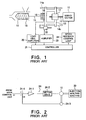
- FIG. 1 an injection unit of a motor-driven injection molding machine to which the present invention is applied is described for the purpose of facilitating the understanding of the present invention.
- rotation of a servo-motor 10 is transmitted to a ball screw 11.
- a nut 12 moves forward or backward in response to the rotation of the ball screw 11.
- the nut 12 is securely fixed to a pressure plate 13.
- the pressure plate 13 is mounted on guide bars 14a and 14b such that the pressure plate 13 is movable along the guide bars 14a and 14b.
- the guide bars 14a and 14b are securely fixed to a frame (not shown) of the injection molding machine.
- the forward or the backward movement of the pressure plate 13 is transmitted to a screw 16 through a rotation shaft 15.
- the screw 16 is placed within an injection cylinder 17.
- the rotation shaft 15 is rotation driven by a rotation driving mechanism that is not shown.
- a bearing 18 is provided between one end of the rotation shaft 15 and the pressure plate 13.
- a load cell 19 is provided adjacent to the bearing 18. The load cell 19 is for use in sensing a reactive force that acts on the screw 16 from a pressurized resin during molding of the resin.
- Molding of resins typically involves in a plurality of processes, i.e., dispensing of resin, filling, dwelling, and cooling.
- molten resin is loaded in the injection cylinder 17.
- the molten resin is filled within a mold by means of moving the screw 16 forward in the injection cylinder 17.
- a pressure is applied to the molten resin filled in the mold to achieve molding.
- the pressure that is applied to the molten resin via the screw 16 is sensed as the reactive force by the load cell 19.
- the pressure sensed by the load cell 19 is amplified by a load cell amplifier 20 and is given to a controller 21.
- the pressure plate 13 is provided with a position sensor 22 for sensing a travel distance of the screw 16.
- the position sensor 22 produces a position sensor signal.
- the position sensor signal is amplified by an amplifier 23 and is supplied to the controller 21.
- the controller 21 supplies to a speed feedback control loop 24 a torque command value for the above mentioned individual processes in accordance with settings made by an operator.
- the speed feedback control loop 24 controls a drive current for the servo-motor 10 based on the torque command value to control an output torque of the servo-motor 10.
- the speed feedback control loop 24 comprises an amplifier 24-1, a motor drive 24-2, a rotation speed sensor 24-3, and a subtracter 24-4.
- the amplifier 24-1 has various functions including a PID compensation.
- the amplifier 24-1 amplifies a speed command signal that is indicative of a speed command value Vr to produce the torque command value for the servo-motor 10.
- the speed command signal is supplied from a main control unit (not shown) for the motor-driven injection molding machine.
- the motor drive 24-2 drives the servo-motor 10 based on the torque command value supplied from the amplifier 24-1.
- the rotation speed sensor 24-3 senses a rotation speed of the servo-motor 10 to produce a rotation speed sensor signal that is indicative of a sensed speed value Vf.
- the subtracter 24-4 is provided on the side of an input of the amplifier 24-1 and subtracts the sensed speed value Vf from the speed command value Vr.
- the subtracter 24-4 produces a result of the subtraction to the amplifier 24-1.
- the injection molding machine is generally depicted by a reference numeral 30 in Fig. 2 .
- To sense the rotation speed of the servo-motor 10 may be achieved by a well-known rotation speed observer rather than the rotation speed sensor 24-3. This is because the rotation speed of the servo-motor can be determined from values of the current and voltage applied to the servo-motor 10.
- the speed feedback control loop as shown in Fig. 2 may generate a disturbance load during a time interval T1 shown in Fig. 3 due to the nature and properties of the resin to be molded.
- the disturbance load is reflected to the sensed speed value Vf of the rotation speed sensor 24-3.
- a speed deviation is produced between the speed command value Vr and the sensed speed value Vf in the subtracter 24-4.
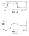
- Fig. 4 shows a change in a pressure Pf that is sensed by the load cell 19.
- a loop gain of the speed feedback control loop i.e., a gain of the amplifier 24-1 may be increased in order to decrease the speed deviation.
- a larger gain results in instability of the speed feedback control loop.
- the output of the amplifier 24-1 that is supplied to the motor drive 24-2 is a torque command value used to follow the speed command value Vr.
- a torque for acceleration or deceleration is required to accelerate or decelerate the servo-motor 10 during an acceleration time interval T2 or a deceleration time intervalT3, respectively, shown in Fig. 3 .
- the torque command value is produced by the amplifier 24-1, so that it is necessary to provide a difference between the speed command value Vr and the sensed speed value Vf, i.e., a speed deviation, to the amplifier 24-1.
- This means that the speed deviation is present when the servo-motor 10 requires a torque.
- the speed deviation can be used as an index for response of the speed feedback control loop.
- the speed deviation can substantially be zero if the amplifier 24-1 has an infinite gain.
- the gain of the amplifier 24-1 may be increased to eliminate a response delay due to the speed deviation.
- a too much larger gain results in instability of the control, which adversely affects the quality of resultant molded products.
- a pressure sensor 31 that is realized by the load cell is provided in a driving system of the screw 16 ( Fig. 1 ) of the injection molding machine 30.
- the pressure sensor 31 may be provided in a portion between the pressure plate 13 and the screw 16 that is used to transmit the driving force.
- the pressure sensor 31 senses an injection pressure that is generated when the molten resin is filled in the mold and is pressurized by means of the screw 16.
- a correction amplifier 32 amplifies a pressure sensor signal produced by the pressure sensor 31.
- the amplified pressure sensor signal is supplied to an adder 23 that is provided between the amplifier 24-1 and the motor drive 24-2.
- the adder 23 adds the output of the amplifier 24-1 and the output of the correction amplifier 32 to supply a result of the addition to the motor drive 24-2.
- the motor drive 24-2 is provided with the torque command value for the servo-motor 10, i.e., the output of the amplifier 24-1, that is added to the output of the correction amplifier 32.
- the pressure value sensed by the pressure sensor 31 is used to correct the torque command value that is supplied to the motor drive 24-2.
- Such correction of the torque command value allows a stable, high response without any deviation between the speed command value Vr and the sensed speed value Vf, as apparent from Fig. 6 .
- This stable and high response can be realized even when the disturbance load is generated due to the nature and properties of the resin to be mold during the time interval T11 in Fig. 6 .
- Fig. 7 shows the pressure sensed by the pressure sensor 31, in which the pressure is converted into a thrust force obtained by the ball screw 11.
- the load cell 19 described in conjunction with Fig. 1 may be substituted for the pressure sensor 31. It is preferable that the correction amplifier 32 amplifies the pressure sensor signal supplied from the pressure sensor 31 with different gains for the forward and the backward movements of the screw 16. More specifically, the gain of the correction amplifier 32 would be a first gain G1 when the screw 16 moves forward, i.e., when the injection pressure is increased. On the other hand, the gain of the correction amplifier 32 would be a second gain G2 (where G1 > G2) when the screw 16 moves backward, i.e., when the injection pressure is decreased. The first and the second gains G1 and G2 are determined depending on transmission efficiency of a driving force transmission mechanism in the injection unit.
- a second embodiment of the present invention is described.
- the second embodiment is characterized in that a differentiator 40 and an acceleration limiter 41 are provided in the speed feedback control loop that is described in conjunction with Fig. 2 .
- the differentiator 40 detects a change in the speed command value Vr.
- the differentiator 40 multiplies the detected value by a predetermined coefficient K to produce a result of the multiplication.
- the multiplication result is supplied to an adder 42 through the acceleration limiter 41.
- the adder 42 adds the multiplication result to the output of the amplifier 24-1 to supply a result of the addition to the motor-driver 24-2.
- the acceleration limiter 41 is described more in detail below.
- a torque command value Tr can be obtained by the following.
- the coefficient K is previously calculated, that is an inertia of the injection molding machine.
- the change in the speed command value Vr is then calculated as a differentiation value and the differentiation value is multiplied by the coefficient K by the differentiator 40.
- the calculated torque command value Tr is added to the command value to the motor drive 24-2 by the adder 42. A result of the addition is supplied to the motor drive 24-2. This eliminates the necessity for the speed deviation and, as shown in Fig. 9 , the speed feedback control loop can be obtained without any response delay.
- the speed feedback control loop as shown in Fig. 8 may be used not only for the speed control but also various other controls including a minor loop for an injection pressure control system or a position control system for the screw 16.
- the range of the acceleration in which the motor-driven injection molding machine can respond is previously known from the inertia and the maximum torque that the servo-motor 10 can generate. It is possible to obtain the speed feedback control loop that can follow the speed command value Vr within a certain specific range of the change rate (or a certain specific range of acceleration). This is achieved by means of limiting the torque command value Tr with the upper and the lower limit values of the acceleration range used as a limit value.
Landscapes
- Engineering & Computer Science (AREA)
- Manufacturing & Machinery (AREA)
- Mechanical Engineering (AREA)
- Injection Moulding Of Plastics Or The Like (AREA)
Claims (5)
- Steuersystem zum Steuern einer motorbetriebenen Spritzgießmaschine mit einer durch einen Servomotor (10) angetriebenen Einspritzeinheit und einer Geschwindigkeitsrückkopplungssteuerungsschleife (24) zum Steuern des Servomotors, wobei die Geschwindigkeitsrückkopplungssteuerungsschleife einen Drehgeschwindigkeitssensor (24-3) zum Erfassen einer Drehgeschwindigkeit des Servomotors als einen erfassten Geschwindigkeitswert, einen Verstärker (24-1) zum Erzeugen eines Befehlssignals, das einen Drehmomentbefehlswert für den Servomotor anzeigt, in Abhängigkeit von einer Differenz zwischen dem durch den Drehgeschwindigkeitsensor (24-3) erfassten Geschwindigkeitswert (vf) und einem Geschwindigkeitsbefehlswert (vr) und eine Motorsteuerung (24-2) zum Steuern des Servomotors in Abhängigkeit vom Drehmomentbefehlswert aufweist;
wobei das Steuersystem ferner aufweist:einen Drucksensor (31), der in einem Antriebssystem für eine in einem Einspritzzylinder angeordnete Schraube angeordnet ist, zum Erfassen eines Harzdrucks und Erzeugen eines den erfassten Druck anzeigenden Signals;einen Korrekturverstärker (32), der mit dem Drucksensor (31) verbunden ist und das den erfassten Druck anzeigende Signal verstärkt, um ein verstärktes Signal als einen Korrekturwert für den Drehmomentbefehlswert zu erzeugen; undeine Addiereinrichtung, die mit dem Verstärker und dem Korrekturverstärker (32) verbunden ist und den Drehmomentbefehlswert zum Korrekturwert für den Drehmomentbefehlswert addiert, um das Additionsergebnis der Motorsteuerung (24-2) zuzuführen. - Steuersystem nach Anspruch 1, wobei der Korrekturverstärker (32) das den erfassten Druck anzeigende Signal mit einem ersten Verstärkungsfaktor G1 multipliziert, wenn die Schraube sich vorwärts bewegt, und das den erfassten Druck anzeigende Signal mit einem zweiten Verstärkungsfaktor G2 multipliziert, wenn die Schraube sich rückwärts bewegt, wobei der zweite Verstärkungsfaktor G2 kleiner ist als der erste Verstärkungsfaktor G1.
- Steuersystem zum Steuern einer motorbetriebenen Spritzgießmaschine mit einer durch einen Servomotor (10) angetriebenen Einspritzeinheit und einer Geschwindigkeitsrückkopplungssteuerungsschleife (24) zum Steuern des Servomotors, wobei die Geschwindigkeitsrückkopplungssteuerungsschleife einen Drehgeschwindigkeitssensor (24-3) zum Erfassen einer Drehgeschwindigkeit des Servomotors als einen erfassten Geschwindigkeitswert, einen Verstärker (24-1) zum Erzeugen eines Befehlssignals, das einen Drehmomentbefehlswert für den Servomotor anzeigt, in Abhängigkeit von einer Differenz zwischen dem erfassten Geschwindigkeitswert (vf) und einem Geschwindigkeitsbefehlswert (vr) und eine Motorsteuerung (24-2) zum Steuern des Servomotors in Abhängigkeit vom Drehmomentbefehlswert aufweist;
wobei das Steuersystem ferner aufweist:eine Differenziereinrichtung (40) zum Differenzieren des Geschwindigkeitsbefehlswertes zum Berechnen einer Beschleunigung und zum Multiplizieren der berechneten Beschleunigung mit einem vorgegebenen Koeffizient (K) zum Erzeugen eines Multiplikationsergebnisses als Korrekturwert für den Drehmomentbefehlswert; undeinen Addierer (42), der mit dem Verstärker (24-1) und der Differenziereinrichtung (40) verbunden ist, zum Addieren des Multiplikationsergebnisses mit dem durch den Verstärker (24-1) erzeugten Drehmomentbefehlswert, um das Additionsergebnis der Motorsteuerung (24-2) zuzuführen. - Steuersystem nach Anspruch 3, ferner mit einer Beschleunigungsbegrenzungseinrichtung (41), die zwischen der Differenziereinrichtung (40) und dem Addierer (42) geschaltet ist, wobei die Begrenzungseinrichtung (41) nur ein Signal innerhalb eines vorgegebenen Beschleunigungsbereichs durchlässt.
- Steuersystem nach Anspruch 3 oder 4, wobei der vorgegebene Koeffizient und der vorgegebene Beschleunigungsbereich für den Fall bestimmt werden, dass ein Trägheitsmoment des Servomotors minimal wird.
Priority Applications (5)
| Application Number | Priority Date | Filing Date | Title |
|---|---|---|---|
| US08/870,485 US5869108A (en) | 1997-06-06 | 1997-06-06 | Control system for controlling a motor-driven injection molding machine |
| DE69739723T DE69739723D1 (de) | 1997-06-09 | 1997-06-09 | Kontrolliervorrichtung mit hohem Ansprechverhalten für eine Motor-angetriebene Spritzgiessmaschine |
| EP97109311A EP0884159B1 (de) | 1997-06-06 | 1997-06-09 | Kontrolliervorrichtung mit hohem Ansprechverhalten für eine Motor-angetriebene Spritzgiessmaschine |
| AT97109311T ATE453497T1 (de) | 1997-06-06 | 1997-06-09 | Kontrolliervorrichtung mit hohem ansprechverhalten für eine motor-angetriebene spritzgiessmaschine |
| SG1997002023A SG67982A1 (en) | 1997-06-09 | 1997-06-09 | Control system for controlling motor-driven injection molding machine with improved response |
Applications Claiming Priority (2)
| Application Number | Priority Date | Filing Date | Title |
|---|---|---|---|
| US08/870,485 US5869108A (en) | 1997-06-06 | 1997-06-06 | Control system for controlling a motor-driven injection molding machine |
| EP97109311A EP0884159B1 (de) | 1997-06-06 | 1997-06-09 | Kontrolliervorrichtung mit hohem Ansprechverhalten für eine Motor-angetriebene Spritzgiessmaschine |
Publications (2)
| Publication Number | Publication Date |
|---|---|
| EP0884159A1 EP0884159A1 (de) | 1998-12-16 |
| EP0884159B1 true EP0884159B1 (de) | 2009-12-30 |
Family
ID=26145527
Family Applications (1)
| Application Number | Title | Priority Date | Filing Date |
|---|---|---|---|
| EP97109311A Expired - Lifetime EP0884159B1 (de) | 1997-06-06 | 1997-06-09 | Kontrolliervorrichtung mit hohem Ansprechverhalten für eine Motor-angetriebene Spritzgiessmaschine |
Country Status (3)
| Country | Link |
|---|---|
| US (1) | US5869108A (de) |
| EP (1) | EP0884159B1 (de) |
| AT (1) | ATE453497T1 (de) |
Families Citing this family (17)
| Publication number | Priority date | Publication date | Assignee | Title |
|---|---|---|---|---|
| JP3776672B2 (ja) * | 2000-03-29 | 2006-05-17 | 日精樹脂工業株式会社 | 射出成形機のモータ駆動装置 |
| AT409105B (de) * | 2000-09-11 | 2002-05-27 | Engel Gmbh Maschbau | Verfahren zum regeln des gegendruckes in einer einrichtung zum plastifizieren und dosieren von kunststoff |
| DE10135539A1 (de) * | 2001-07-20 | 2003-03-27 | Mannesmann Plastics Machinery | Regelverfahren für eine Spritgießmaschine |
| US8033808B2 (en) * | 2007-08-24 | 2011-10-11 | Delta Pt, Llc | Pressure compensating molding system |
| JP5207799B2 (ja) * | 2008-03-31 | 2013-06-12 | 東洋機械金属株式会社 | インラインスクリュー式射出成形機およびその制御方法 |
| US9222618B2 (en) | 2010-11-29 | 2015-12-29 | Lincoln Industrial Corporation | Stepper motor driving a lubrication pump providing uninterrupted lubricant flow |
| US9388940B2 (en) | 2010-11-29 | 2016-07-12 | Lincoln Industrial Corporation | Variable speed stepper motor driving a lubrication pump system |
| US9022177B2 (en) | 2010-11-29 | 2015-05-05 | Lincoln Industrial Corporation | Pump having stepper motor and overdrive control |
| DE112011105485T5 (de) * | 2011-08-01 | 2014-06-12 | Mitsubishi Electric Corporation | Steuervorrichtung und Steuerverfahren für eine Spritzgussmaschine |
| CN102975344B (zh) * | 2012-11-19 | 2015-10-28 | 海天塑机集团有限公司 | 注塑机电机温度控制机构 |
| CN105027013B (zh) * | 2013-03-07 | 2017-09-19 | 株式会社牧野铣床制作所 | 机床的进给轴控制方法及进给轴控制装置 |
| JP6100051B2 (ja) * | 2013-03-26 | 2017-03-22 | 住友重機械工業株式会社 | 射出成形機 |
| US9671065B2 (en) | 2013-10-17 | 2017-06-06 | Lincoln Industrial Corporation | Pump having wear and wear rate detection |
| KR20160030047A (ko) * | 2014-09-08 | 2016-03-16 | 인글라스 에스피에이 | 플라스틱 재료를 인젝션 몰딩하기 위한 방법 및 장치 |
| JP6212069B2 (ja) * | 2015-05-12 | 2017-10-11 | ファナック株式会社 | 可動部をモータで駆動制御する射出成形機 |
| MX387617B (es) * | 2015-12-14 | 2025-03-18 | Imflux Inc | Controlador remoto para el control de aparatos mediante la desviacion de la señal de retroalimentacion del controlador nativo al controlador remoto y metodos para el mismo. |
| CA3006786C (en) * | 2015-12-14 | 2020-06-30 | iMFLUX Inc. | Remote controller for controlling apparatus by diverting feedback signal from native controller to the remote controller and methods for same |
Family Cites Families (13)
| Publication number | Priority date | Publication date | Assignee | Title |
|---|---|---|---|---|
| JPS61167519A (ja) * | 1985-01-21 | 1986-07-29 | Fanuc Ltd | 射出成形機の射出・保圧制御方法 |
| EP0364599B1 (de) * | 1988-03-08 | 1994-05-18 | Fanuc Ltd. | Verfahren und vorrichtung zur drucksteuerung einer elektrisch angetriebenen spritzgiessmaschine |
| JPH082566B2 (ja) * | 1988-07-08 | 1996-01-17 | ファナック株式会社 | 電動式射出成形機の射出制御方式 |
| JPH03213323A (ja) * | 1990-01-18 | 1991-09-18 | Nissei Plastics Ind Co | 射出成形機の圧力制御方法 |
| JP2913233B2 (ja) * | 1992-08-10 | 1999-06-28 | 住友重機械工業株式会社 | 電動式射出成形機の圧力制御装置 |
| JP2628266B2 (ja) * | 1993-03-31 | 1997-07-09 | 日精樹脂工業株式会社 | 射出成形機の速度制御方法及び装置 |
| US5331264A (en) * | 1993-04-15 | 1994-07-19 | Fanuc Robotics North America, Inc. | Method and device for generating an input command for a motion control system |
| US5380181A (en) * | 1993-06-21 | 1995-01-10 | Sumitomo Heavy Industries, Ltd. | Control device for an electric injection molding machine |
| JPH0752210A (ja) * | 1993-08-11 | 1995-02-28 | Fanuc Ltd | 射出成形機の射出制御装置 |
| JP2657352B2 (ja) * | 1993-09-08 | 1997-09-24 | 日精樹脂工業株式会社 | 射出成形機の圧力検出方法及び装置 |
| US5421712A (en) * | 1993-10-05 | 1995-06-06 | Industrial Technology Research Institute | Screw rotating and advancing device for an injection molding machine |
| JPH07244520A (ja) * | 1994-03-03 | 1995-09-19 | Fanuc Ltd | 干渉トルクを考慮した自動機械の加減速制御方法 |
| JP3547845B2 (ja) * | 1995-04-25 | 2004-07-28 | 東芝機械株式会社 | 射出成形機の射出速度制御方法および装置 |
-
1997
- 1997-06-06 US US08/870,485 patent/US5869108A/en not_active Expired - Lifetime
- 1997-06-09 AT AT97109311T patent/ATE453497T1/de not_active IP Right Cessation
- 1997-06-09 EP EP97109311A patent/EP0884159B1/de not_active Expired - Lifetime
Also Published As
| Publication number | Publication date |
|---|---|
| ATE453497T1 (de) | 2010-01-15 |
| US5869108A (en) | 1999-02-09 |
| EP0884159A1 (de) | 1998-12-16 |
Similar Documents
| Publication | Publication Date | Title |
|---|---|---|
| EP0884159B1 (de) | Kontrolliervorrichtung mit hohem Ansprechverhalten für eine Motor-angetriebene Spritzgiessmaschine | |
| US5371450A (en) | Control unit capable of smoothly carrying out a switching operation between position and pressure feedback control systems | |
| US4735564A (en) | Injection molding machine | |
| CA2396544C (en) | Electric injection molding machine and method of controlling injection speed and injection pressure of electric injection molding machine | |
| JP2913233B2 (ja) | 電動式射出成形機の圧力制御装置 | |
| EP0089156B1 (de) | Verfahren und Vorrichtung zur Steuerung der Beschleunigung und Abbremsung | |
| US5380181A (en) | Control device for an electric injection molding machine | |
| JP5383193B2 (ja) | 電気サーボプレス機での力を制御および調整するための方法および装置 | |
| EP1136226B1 (de) | Verfahren und Vorrichtung zum Steuern einer Spritzgiessmaschine geeignet zum Reduzieren der Gewichtsänderungen von Formkörpern | |
| US6565781B2 (en) | Method for controlling screw position in an injection molding machine | |
| EP0285664B1 (de) | Vorrichtung zum feststellen einer formberührungsposition in einer elektrisch angetriebenen, unmittelbar wirkenden formschliessvorrichtung | |
| US5336073A (en) | Injection pressure limiting device for injection molding machine | |
| JP2961582B2 (ja) | 射出成形機の制御装置 | |
| US5533884A (en) | Speed control unit for an injection molding machine | |
| CN1073918C (zh) | 控制电机驱动注模机改进灵敏度的控制系统 | |
| JP2798170B2 (ja) | ダイカストマシンの射出装置 | |
| US5844391A (en) | Device for controlling the clamping force of a motor-driven injection molding machine | |
| JP3313144B2 (ja) | サーボモータ駆動方式プレス機械の駆動制御装置 | |
| KR100230086B1 (ko) | 개선된 응답성을 갖도록 모터 구동식 사출 성형기를 제어하기 위한 제어 장치 | |
| JP3245684B2 (ja) | 電動式射出成形機の圧力制御装置 | |
| JP3023539B2 (ja) | 電動射出成形機の射出速度制御方式 | |
| JP2926286B2 (ja) | 射出成形機の制御装置 | |
| JP2746473B2 (ja) | 電動射出成形機の射出速度制御方法 | |
| JP3114054B2 (ja) | 電動射出成形機の速度制御方式 | |
| JP2628773B2 (ja) | 電動射出成形機の射出圧力制限装置 |
Legal Events
| Date | Code | Title | Description |
|---|---|---|---|
| PUAI | Public reference made under article 153(3) epc to a published international application that has entered the european phase |
Free format text: ORIGINAL CODE: 0009012 |
|
| AK | Designated contracting states |
Kind code of ref document: A1 Designated state(s): AT CH DE FR GB IT LI |
|
| 17P | Request for examination filed |
Effective date: 19990526 |
|
| AKX | Designation fees paid |
Free format text: AT CH DE FR GB IT LI |
|
| 17Q | First examination report despatched |
Effective date: 20021220 |
|
| GRAP | Despatch of communication of intention to grant a patent |
Free format text: ORIGINAL CODE: EPIDOSNIGR1 |
|
| GRAS | Grant fee paid |
Free format text: ORIGINAL CODE: EPIDOSNIGR3 |
|
| GRAA | (expected) grant |
Free format text: ORIGINAL CODE: 0009210 |
|
| AK | Designated contracting states |
Kind code of ref document: B1 Designated state(s): AT CH DE FR GB IT LI |
|
| REG | Reference to a national code |
Ref country code: GB Ref legal event code: FG4D |
|
| REG | Reference to a national code |
Ref country code: CH Ref legal event code: EP |
|
| REF | Corresponds to: |
Ref document number: 69739723 Country of ref document: DE Date of ref document: 20100211 Kind code of ref document: P |
|
| PG25 | Lapsed in a contracting state [announced via postgrant information from national office to epo] |
Ref country code: AT Free format text: LAPSE BECAUSE OF FAILURE TO SUBMIT A TRANSLATION OF THE DESCRIPTION OR TO PAY THE FEE WITHIN THE PRESCRIBED TIME-LIMIT Effective date: 20091230 |
|
| PLBE | No opposition filed within time limit |
Free format text: ORIGINAL CODE: 0009261 |
|
| STAA | Information on the status of an ep patent application or granted ep patent |
Free format text: STATUS: NO OPPOSITION FILED WITHIN TIME LIMIT |
|
| 26N | No opposition filed |
Effective date: 20101001 |
|
| REG | Reference to a national code |
Ref country code: CH Ref legal event code: PL |
|
| GBPC | Gb: european patent ceased through non-payment of renewal fee |
Effective date: 20100609 |
|
| REG | Reference to a national code |
Ref country code: FR Ref legal event code: ST Effective date: 20110228 |
|
| PG25 | Lapsed in a contracting state [announced via postgrant information from national office to epo] |
Ref country code: IT Free format text: LAPSE BECAUSE OF FAILURE TO SUBMIT A TRANSLATION OF THE DESCRIPTION OR TO PAY THE FEE WITHIN THE PRESCRIBED TIME-LIMIT Effective date: 20091230 |
|
| PG25 | Lapsed in a contracting state [announced via postgrant information from national office to epo] |
Ref country code: LI Free format text: LAPSE BECAUSE OF NON-PAYMENT OF DUE FEES Effective date: 20100630 Ref country code: CH Free format text: LAPSE BECAUSE OF NON-PAYMENT OF DUE FEES Effective date: 20100630 |
|
| PG25 | Lapsed in a contracting state [announced via postgrant information from national office to epo] |
Ref country code: FR Free format text: LAPSE BECAUSE OF NON-PAYMENT OF DUE FEES Effective date: 20100630 |
|
| PG25 | Lapsed in a contracting state [announced via postgrant information from national office to epo] |
Ref country code: GB Free format text: LAPSE BECAUSE OF NON-PAYMENT OF DUE FEES Effective date: 20100609 |
|
| PGFP | Annual fee paid to national office [announced via postgrant information from national office to epo] |
Ref country code: DE Payment date: 20130605 Year of fee payment: 17 |
|
| REG | Reference to a national code |
Ref country code: DE Ref legal event code: R119 Ref document number: 69739723 Country of ref document: DE |
|
| REG | Reference to a national code |
Ref country code: DE Ref legal event code: R119 Ref document number: 69739723 Country of ref document: DE Effective date: 20150101 |
|
| PG25 | Lapsed in a contracting state [announced via postgrant information from national office to epo] |
Ref country code: DE Free format text: LAPSE BECAUSE OF NON-PAYMENT OF DUE FEES Effective date: 20150101 |