EP0883199A1 - Negative electrode materials for non-aqueous electrolyte secondary batteries and said batteries employing the same materials - Google Patents
Negative electrode materials for non-aqueous electrolyte secondary batteries and said batteries employing the same materials Download PDFInfo
- Publication number
- EP0883199A1 EP0883199A1 EP98110110A EP98110110A EP0883199A1 EP 0883199 A1 EP0883199 A1 EP 0883199A1 EP 98110110 A EP98110110 A EP 98110110A EP 98110110 A EP98110110 A EP 98110110A EP 0883199 A1 EP0883199 A1 EP 0883199A1
- Authority
- EP
- European Patent Office
- Prior art keywords
- lithium
- solid phase
- negative electrode
- aqueous electrolyte
- discharge
- Prior art date
- Legal status (The legal status is an assumption and is not a legal conclusion. Google has not performed a legal analysis and makes no representation as to the accuracy of the status listed.)
- Granted
Links
Images

Classifications
-
- H—ELECTRICITY
- H01—ELECTRIC ELEMENTS
- H01M—PROCESSES OR MEANS, e.g. BATTERIES, FOR THE DIRECT CONVERSION OF CHEMICAL ENERGY INTO ELECTRICAL ENERGY
- H01M4/00—Electrodes
- H01M4/02—Electrodes composed of, or comprising, active material
- H01M4/13—Electrodes for accumulators with non-aqueous electrolyte, e.g. for lithium-accumulators; Processes of manufacture thereof
-
- H—ELECTRICITY
- H01—ELECTRIC ELEMENTS
- H01M—PROCESSES OR MEANS, e.g. BATTERIES, FOR THE DIRECT CONVERSION OF CHEMICAL ENERGY INTO ELECTRICAL ENERGY
- H01M4/00—Electrodes
- H01M4/02—Electrodes composed of, or comprising, active material
- H01M4/36—Selection of substances as active materials, active masses, active liquids
-
- H—ELECTRICITY
- H01—ELECTRIC ELEMENTS
- H01M—PROCESSES OR MEANS, e.g. BATTERIES, FOR THE DIRECT CONVERSION OF CHEMICAL ENERGY INTO ELECTRICAL ENERGY
- H01M4/00—Electrodes
- H01M4/02—Electrodes composed of, or comprising, active material
- H01M4/36—Selection of substances as active materials, active masses, active liquids
- H01M4/38—Selection of substances as active materials, active masses, active liquids of elements or alloys
- H01M4/40—Alloys based on alkali metals
-
- Y—GENERAL TAGGING OF NEW TECHNOLOGICAL DEVELOPMENTS; GENERAL TAGGING OF CROSS-SECTIONAL TECHNOLOGIES SPANNING OVER SEVERAL SECTIONS OF THE IPC; TECHNICAL SUBJECTS COVERED BY FORMER USPC CROSS-REFERENCE ART COLLECTIONS [XRACs] AND DIGESTS
- Y02—TECHNOLOGIES OR APPLICATIONS FOR MITIGATION OR ADAPTATION AGAINST CLIMATE CHANGE
- Y02E—REDUCTION OF GREENHOUSE GAS [GHG] EMISSIONS, RELATED TO ENERGY GENERATION, TRANSMISSION OR DISTRIBUTION
- Y02E60/00—Enabling technologies; Technologies with a potential or indirect contribution to GHG emissions mitigation
- Y02E60/10—Energy storage using batteries
Definitions
- the present invention relates to non-aqueous electrolyte secondary batteries employing organic electrolyte, solid polymer electrolyte or the like, and more particularly to negative electrode materials thereof featuring a high capacity, high reliability for the safety aspect, a little decrease of discharge capacity resulting from cycles, and excellent high-rate charge and discharge characteristics.
- a lithium battery employing lithium as negative active material in general, generates high electromotive force and can be high energy density.
- the lithium batteries thus employ various positive active materials combined with the negative active material, and are commercialized to be battery systems, thereby reducing dimensions as well as weights of cordless and portable products.
- the electrolyte of the lithium batteries employs non-aqueous electrolyte, e.g., 1) organic electrolyte made of dehydrated aprotic organic solvent dissolving lithium salt, and 2) solid polymer electrolyte.
- non-aqueous electrolyte e.g., 1) organic electrolyte made of dehydrated aprotic organic solvent dissolving lithium salt, and 2) solid polymer electrolyte.
- the lithium batteries are thus sometimes called non-aqueous electrolyte primary battery and non-aqueous electrolyte secondary battery.
- transition metal element oxides including vanadium pentoxide (V 2 O 5 ), titanium disulfide (TiS 2 ), molybdenum disulfide (MoS 2 ) and chalcogenide were examined at first; however, recently, lithium contained transition metal element oxides of which transition metal element is partially replaced with another element have been examined.
- the oxides of lithium contained transition metal element such as LiCoO 2 , LiNiO 2 , LiMn 2 O 4 which are double oxides of lithium and cobalt, lithium and nickel, and lithium and manganese. These double oxides repeat desorption and absorption of lithium ion by charge and discharge, whereby excellent cycle life characteristics can be obtained.
- the chalcogenide one of the lithium contained transition metal element, is also examined besides these double oxides.
- metal lithium which is active material could be the most desirable material from the standpoint of energy density provided it can be used as it is, because an electric potential would be least-noble.
- active dendrite or mossy crystal having a large specific surface area deposits on the negative electrode surface, and the crystals thereof react with the solvent in the electrolyte, whereby being deactivated with ease, which lowers the capacity of the battery rapidly, and therefore, a larger quantity of metal lithium must be pre-filled in the negative electrode. Further, the deposited dendrite might penetrate the separator and cause an internal short circuit. These problems shorten the cycle life and affect the product safety.
- Li-Al alloy Li-Al alloy
- alloy of Li and Wood's metal which is fusible alloy.
- a carbon material such as graphite is employed as a host material of the negative electrode, because such a carbon material is able to absorb and desorb lithium ion by charge and discharge.
- the carbon material as a negative electrode material, the lithium contained cobalt oxide as a positive electrode material and organic electrolyte are combined to make a system called lithium-ion secondary battery, which is now available in the market.
- the above materials absorb lithium into crystal lattice thereof by charging, and desorb lithium by discharging. Repeated charge and discharge neither swells nor shrinks the skeletal crystal extensively, and fineness of the crystal particles progresses little. An excellent cycle characteristic thus can be expected.
- a non-aqueous electrolyte secondary battery as a power supply of an apparatus is required the following features: 1. High capacity, 2. Long cycle life, 3. Chargeable/dischargeable with a high rate. In other words, if a negative electrode material has an extraordinary high capacity but has poor charge and discharge characteristics, it is impossible to reduce both size and weight of the power supply for some applications.
- an electrochemical activity of the particle surface of the negative electrode material is a key factor for improving the charge and discharge characteristics.
- silicon has an advantage such as absorbing and desorbing a lot of lithium during charge-transfer reaction under high-rate charge and discharge.
- silicides described previously is employed as the negative electrode material, an excellent cycle characteristic can be expected because of superior oxidation and reduction reaction during the charge and discharge according to the function of a mixed conductor for electrons and lithium ions.
- this material has an inferior characteristic of high-rate charge and discharge due to relatively smaller power of absorbing and desorbing lithium.
- the present invention aims to provide a negative electrode material for a non-aqueous electrolyte secondary battery, the material features high reliability from the safety view of point, high capacity, less decreasing of discharge capacity due to cycles, and excellent high-rate charge and discharge characteristics.
- the present invention covers a composite particle comprises the following elements:
- the composite particle comprises the solid phase A and solid phase B, where the solid phase A is formed by at least one of the elements below, or either solid solution or an intermetallic compound, each of them including at least one of the elements below:
- Fig. 1 is a vertical cross sectional view of a coin type test cell for evaluating charge and discharge efficiency and electrochemical characteristics of negative electrode materials of the present invention.
- Fig. 2 is a vertical cross sectional view of a cylindrical cell utilized in an exemplary embodiment of a non-aqueous electrolyte secondary battery having a negative electrode which employs the material of the present invention.
- sample powder into a plastic cylinder whose inner diameter is 25 mm. Apply pressure of 408 kgf ⁇ cm -2 to the sample powder.
- the plastic cylinder has metallic dies fit into both ends of the cylinder. Insert a metal rod into the cylinder, and measure an ohmic resistance value between the metal dies, (the sample powder is sandwiched between the metal dies,) with LORESTA-SP (MCP-T500) made by Mitsubishi Chemical Co., Ltd., and then find the electronic conductivity from the ohmic resistance.
- sample powder into a plastic cylinder of which inner diameter is 10 mm, and apply pressure of 2546 kg ⁇ cm -2 to the powder to mold pellets.
- the pellet is covered on its both end faces by glassy solid electrolyte, of which thickness is ca. 1.0 mm, and expressed as 0.01 Li 3 PO 4 + 0.63 Li 2 S + 0.36 SiS 2 .
- the glossy solid electrolyte has lithium ionic conductivity. Further, cover the outside of the pellet with metal lithium of approx. 1 mm thickness. Then apply pressure of 5093 kgf ⁇ cm -2 to both faces of the pellet, and measure resistance value with an AC impedance measuring device made by Solartron Co., Ltd. in the U.K. , finally find the lithium ionic conductivity from the measured resistance value.
- a cell case 1 and a cover 2 both made of stainless steel are sealed gas-tightly and liquid-tightly via a gasket 7 made from polypropylene.
- a negative material mold electrode 5 is molded with a current collector 3 into one body, meanwhile, the current collector 3 is made of stainless steel expanded metal and welded to an inner bottom face of the cell case 1.
- a disk-type metal lithium electrode 4 is press fit to an inner face of the cover 2.
- the negative material mold electrode 5 is separated from the metal lithium electrode 4 by a separator 6 made of microporous polypropylene membrane. Organic electrolyte impregnates between the electrodes and into the negative material mold electrode 5 as well as the separator 6.
- the negative material mold electrode 5 is made of predetermined quantity of a mix which is molded with the current collector 3 into one body.
- the mix comprises (a) negative material powder 85%, (b) binder 10% made of polyvinylidene fluoride and (c) conductive agent 5% made of acetylene black. These percentages represent the relative weight ratios among the materials.
- the organic electrolyte is produced by using the following materials and steps: Prepare a mixed solvent made from ethylene carbonate (EC) and di-ethyl carbonate (DEC) in an equal volume of each, then, dissolve the solute lithium hexafluorophosphate (LiPF 6 ), which is an electrolyte, into the mixed solvent, and finally, adjust the concentration thereof at 1 mol ⁇ 1 -1 .
- EC ethylene carbonate
- DEC di-ethyl carbonate
- test cell can be interpreted as this: a regular coin-type lithium primary battery, e.g., CR2016 type manganese dioxide lithium battery, of which manganese dioxide positive electrode is replaced with the negative material mold electrode.
- a regular coin-type lithium primary battery e.g., CR2016 type manganese dioxide lithium battery, of which manganese dioxide positive electrode is replaced with the negative material mold electrode.
- test temperature 20°C
- charge and discharge with current density of 0.5 mA ⁇ cm -2 constant current and discharge up to 3V, then charge down to 0V, repeat this discharge/charge 50 cycles.
- Table 1(A) lists the following items; (a) mixing ratios of the raw materials for the negative electrode material prepared, (b) heating temperature, (c) component of the solid phases A and B of the negative electrode material prepared and (d) the electronic conductivity as well as ionic conductivity of the solid phase B.
- Table 1(B) lists the following data both at the initial cycle and at the 50 th cycle; charge and discharge capacities, efficiency thereof, and the change ratio of discharge capacity, where, the efficiency of charge and discharge is represented by: (discharge capacity/charge capacity) ⁇ 100, and the change ratio of discharge capacity is represented by (discharge capacity at the 50 th cycle/discharge capacity at 1 st cycle) ⁇ 100.
- Table 1(B) also lists the following data of the conventional materials in order to show a comparison list with each sample used in the embodiments of the present invention.
- For the comparison produce the negative electrode material based on the same condition as the above sample by using a host material which is able to absorb and desorb lithium ion through charge and discharge, and also produce the test cell based on the same condition, then perform the charge and discharge cycling test.
- the following conventional materials are employed in this test:
- the samples 1-8 used in the exemplary embodiment 1 of the present invention are proved composite particles by EPMA method, i.e., the composite particles comprise the following materials:
- the powders of each sample used in the first exemplary embodiment are composite particles formed by peritectic phenomenon.
- the discharge capacity at the initial cycle of each sample powder is at least 650 mAh ⁇ cm -3 which is approximately the same level as those of the conventional case 1 (silicon) and case 2 (complex of silicon and carbon), and higher level than those of the conventional case 3 (natural graphite) and case 4(Mg 2 Si).
- the conventional cases 1 and 2 which indicated large discharge capacities at the initial cycle, show drastic decreases, while the conventional cases 3 (natural graphite) and 4 (Mg 2 Si) show little change in the discharge capacities.
- Each sample powder used in the first exemplary embodiment of the present invention retains at least 75% of the discharge capacity sustainable rate, and has a larger discharge capacity than those of the conventional cases 3 and 4 by 10-30%.
- the metal lithium forming the solid phase A has a high capacity density in itself; however, it shows a drastic decrease in a discharge capacity.
- the intermetallic compounds of lithium and respective element being able to alloy with lithium, which forms the solid phase B is the mixed conductor and has excellent cycle characteristics; however, the capacity density thereof is not so high.
- the solid phase B having the excellent cycle characteristics restrains the metal lithium which has high capacity density and forms the solid phase A from being decreased in the discharge capacity due to the charge and discharge cycles, i.e., the solid phases A and B complement each other.
- the composite particle used in the first exemplary embodiment of the present invention has included lithium (active material) in the form of metal or intermetallic compound
- this composite particle as the negative electrode material of a battery system such as a practical secondary battery of which operation is started by discharge
- the positive electrode material of this battery system should be selected from oxides and chalcogenides of the transition metal element such as V2O5, TiS2, MoS2 (these correspond to charged condition), and then, organic electrolyte is impregnated into this material, and finally, the positive electrode is assembled.
- a different point from the first exemplary embodiment is to start the test by initial charging, while the test in the first exemplary embodiment starts with discharging.
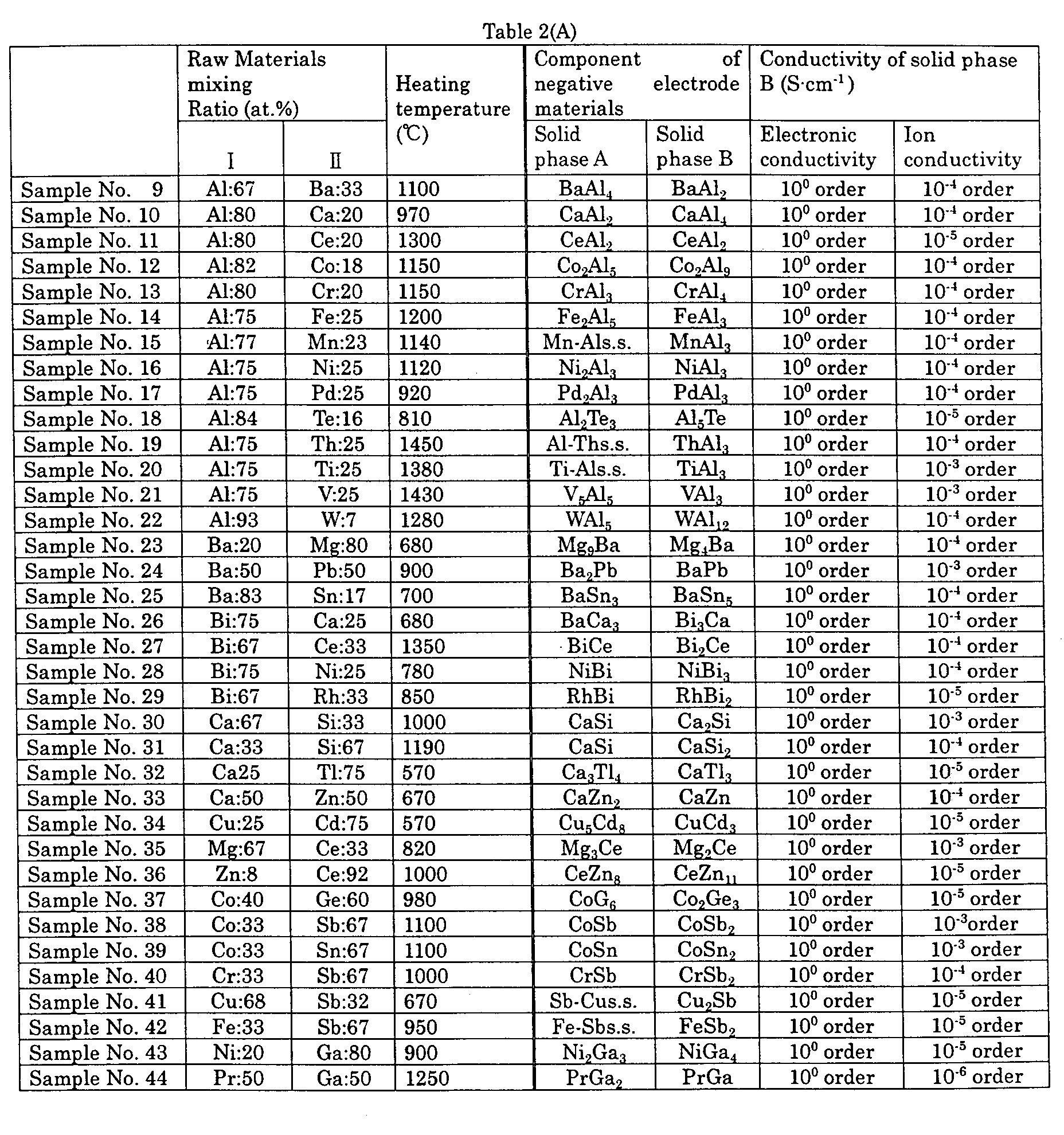
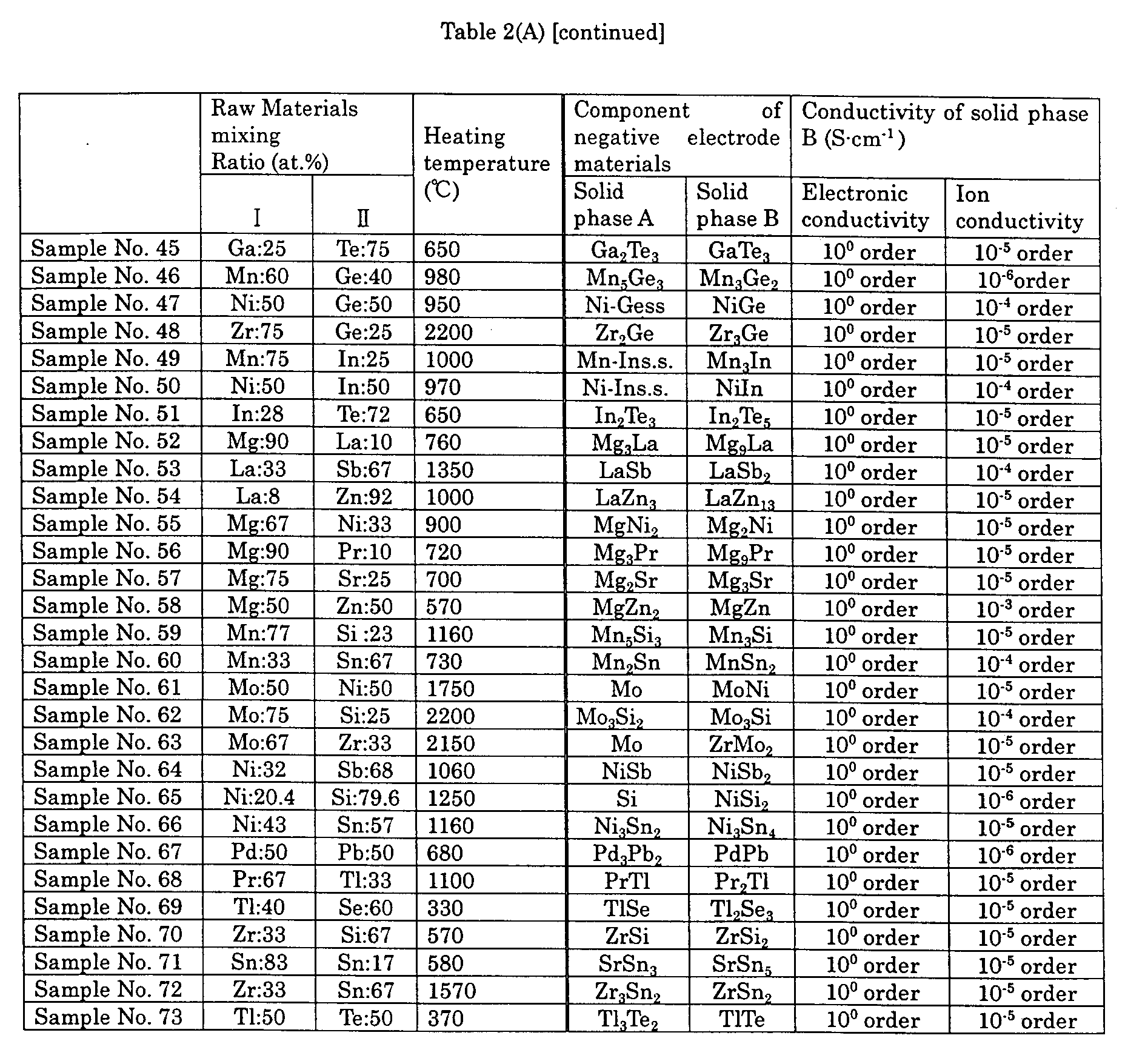
- Table 2(A) shows the following data of the solid phases A and B: mixing ratio, heating temperature of the materials in preparing the negative electrode material, component of the solid phases A and B, and electronic as well as ionic conductivity of the solid phase B.
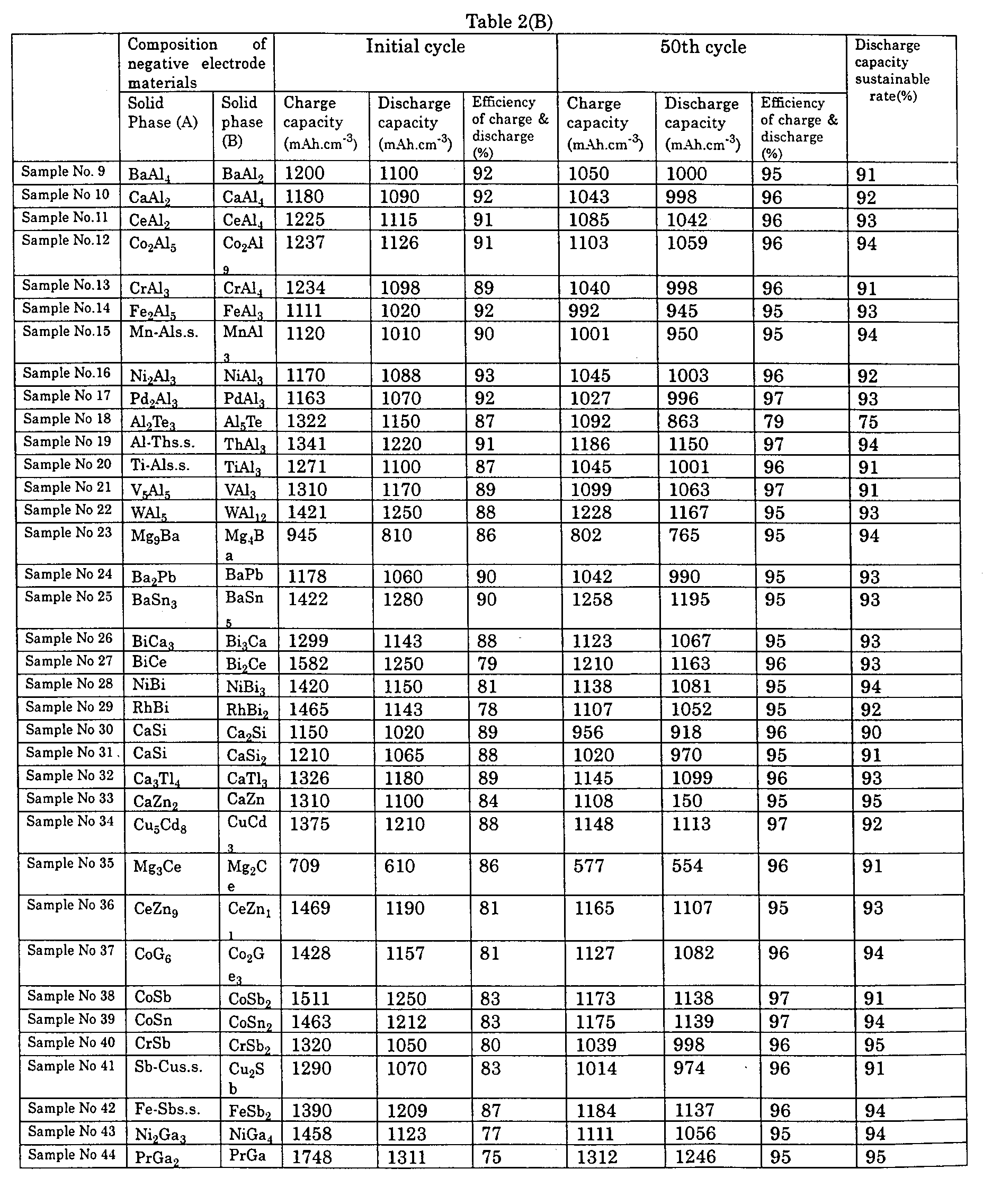
- Table 2(B) shows the following data both at the initial cycle and the 50 th cycle of the test cell employing the prepared negative electrode material: charge and discharge capacities, efficiency of charge and discharge and discharge capacity sustainable rate.
- the solid phase A of sample No. 15 is indicated as Mn-Als.s., which means the sample is formed by s olid s olutions of Mn and Al.
- the same interpretation can be applied to the sample Nos. 19, 20, 41, 42, 47, 49 and 50, which are formed also solid solutions.
- the solid phases A of sample Nos. 61, 63 and 65 are formed by single element Mo and Si respectively.
- the other samples' solid phases A and B are formed by intermetallic compound made from two elements.
- Each sample used in the second exemplary embodiment is a composite particle comprising the core formed by the solid phase A, and the solid phase B which wraps the core resulting from peritectic phenomenon.
- the solid phase B as shown in Table 2(A), is a mixed conductor having electronic conductivity and lithium ionic conductivity, same as used in the first exemplary embodiment.
- Table 2(B) proves that the discharge capacity of each sample in the second exemplary embodiment at the initial cycle is greater than those of the conventional cases 1-4 shown in Table 1(B), in particular, eight samples including the sample Nos. 23, 35, 52, 55, 56, 57, 61 and 63 indicate at least 1000 mAh ⁇ cm -3 of discharge capacity.
- These negative electrode materials of high capacity include at least one of the following elements which are able to alloy with lithium (active material) in the solid phase A: zinc, cadmium, aluminum, gallium, indium, thallium, silicon, germanium, tin, lead, antimony and bismuth.
- the sample No. 65 indicates the largest discharge capacity (1450 mAh ⁇ cm -3 ) of which core comprising the solid phase A is formed by silicon.
- every sample used in the second exemplary embodiment indicates at least 75% and has a greater charge and discharge efficiency than those of the conventional case 1 (silicon), case 2 (complex of silicon and carbon) and case 4 (Mg 2 Si); however, many of the samples have less capacity than the conventional case 3 (natural graphite indicated 91%), and yet, several samples (e.g., sample Nos. 9-12, 14, 16, 17 and 19) show not less than the charge and discharge efficiency of the case 3.
- every sample indicates at least 75%, and majority of the samples indicate 90% or more. These values are less than the conventional case 3 (natural graphite) and case 4 (Mg 2 Si). On the other hand, the samples indicate far less decrease of discharge capacity due to cycles than those of the conventional case 1 (silicon) and case 2 (complex of silicon and carbon.)
- the solid phase A is formed by, as previously described, at least one of the following elements which absorb and desorb a large amount of lithium by charge and discharge: zinc, cadmium, aluminum, gallium, indium, thallium, silicon, germanium, tin, lead, antimony and bismuth, or formed by either a solid solution or intermetallic compound including an element which is able to alloy with lithium as described above.
- sample Nos. 2 used in the first exemplary embodiment
- sample Nos. 9-17 19-44, 46-50, 52-61, 63-68 and 70-72 in the second exemplary embodiment.
- the solid phase B is formed by either a solid solution or intermetallic compound including at least one element selected from a group of alkaline earth elements and transition metal elements.
- Tables 2(A) and 2(B) did not list the following samples, Mg 2 Si, Mg 2 Pb, Mg 2 Sn, Mg 2 Ge, and transition metal element silicides other than NiSi, such as FeSi 2 , CoSi 2 , they have great potentials for forming the solid phase B.
- silicon forming the solid phase A is able to alloy with lithium.
- silicon alone is employed in the negative electrode as a host material (corresponding to the conventional case 1)
- an initial charge capacity at the initial cycle indicates, as shown in Table 1(B), 5600 mAh ⁇ cm -3 as well as such a large amount exceeding 4000 mAh ⁇ g -1 .
- the crystal structure of silicon changes, i.e., a lattice interval of a crystal expands, and a swelling volume reaches to max. four times, which results in a crack on crystal particle boundaries of silicon.
- the silicon particle having the higher electric resistance due to progressive fineness finds itself difficult to be alloyed, and only the silicon particle that has a relatively higher electronic conductivity and does not progress in fineness is alloyed, the charge capacity of the battery thus reaches to as low as 20% that of the initial charge. Silicon progresses in fineness at the 2 nd cycle discharge, and the discharge capacity further lowers accordingly. Repeating charge and discharge less than 20 cycles brings the battery being unable to charge or discharge at all. In the negative electrode in such a condition, the specific surface area increases due to progressive fineness of silicon, and also a lot of dead lithium exists, therefore, the negative electrode is extremely unstable from the thermal view of point, and thus this condition involves safety concern.
- NiSi 2 forming the solid phase B of sample No. 65 absorbs and disorbs lithium by charge and discharge within the crystal lattices, thus the crystal structure changes little. As a result, the crystal swells and shrinks little, and the particle fineness does not progress, neither dead lithium nor increasing of the specific surface area can be observed. Accordingly, it is not worth worrying drastic decrease of discharge capacity due to cycles; however, the employment of NiSi 2 still cannot provide a satisfactory level of high capacity when a high capacity-oriented battery is desired with the discharge capacity of 250 mAh ⁇ g -1 . Such a small discharge capacity is disadvantage for evaluating a high rate charge and discharge characteristics.
- a host material of lithium comprising the solid phase A formed by Si and the solid phase B formed by NiSi 2 is employed as the negative electrode material.
- Si and NiSi 2 are bound each other strongly at the boundary face, and easy to be electrically conductive.
- NiSi 2 swells and shrinks far less than Si does, and thus restrains Si from swelling and shrinking within two times of the original volume which is restorable elastic limit for the crystal structure.
- the amount of lithium absorbed and disorbed by charge and discharge decreases responsive to the restrained amount of Si, and is less than the case where Si alone is used.
- the solid phase B which comprises NiSi 2 , a mixed conductor having electronic and lithium ionic conductivity, wraps the solid phase A comprising Si, electrons can move between Si and NiSi 2 as described above.
- the total lithium amount absorbed into Si and NiSi 2 is less than the case of Si alone, and yet, it is substantially greater than the case of NiSi 2 alone.
- the negative electrode shows the less decrease of discharge capacity due to cycles, and has the greater capacity than those of the conventional case 3 (natural graphite) and case 4 (Mg 2 Si) both of which have excellent cycle characteristics and relatively high capacities.
- the safety of the negative electrode material for non-aqueous electrolyte secondary battery is tested with "solder iron method" named by the inventors' group.
- the method is as follows: First, charge the test cell which underwent the 50-cycle charge and discharge test, and second, disassemble the test cell in a glove box under dry air of less than 5% relative humidity, then, dry vacuum the disassembled cell. Then, press a solder iron heated up to ca. 300°C to the negative material mold electrode 5 which has been molded with the current collector 3 into one body still remained in the cell case. Then, the following phenomena are observed:
- Embodiment 1 and Embodiment 2 of the present invention There are no white fuming, spark, or combustion, thus no change is observed. As a result, the samples of the present invention are proved to be the most reliable from the safety view of point.
- the negative electrode material comprising the composite particles formed by the solid phases A and B is highly safety and has the less decrease of discharge capacity due to cycles as well as the higher capacity than the conventional materials.
- variation of a material mixing ratio (at.%) between Si and Ni, particle size (average) variation due to pulverize, and resulting specific surface area variation thereof, are discussed what influences these variations give the charge and discharge characteristics.
- Table 3 The test result is shown in Table 3.
- Table 4 lists the following data: Each sample of the conventional cases 1-4 are sifted into several groups depending on the particle size, each group thus has a specific surface area responsive to the particle size. Each group undergoes 50 cycles of charge and discharge. The test result is listed in Table 4.
- Sample Nos. 74 a-f (the percentage content of the solid phase B is 30%, and the solid phase B is assumed NiSi 2 ) drastically lower the discharge capacity sustainable rate down to as low as 20-30% after the 50 th cycle.
- Sample Nos. 75 a-f, 76 a-f, 77 a-f and 78 a-f maintain the rate at as high as 97-98%.
- the percentage content of NiSi 2 which forms the solid phase B is rather low at 30%, and the percentage content of Si in the solid phase A is high.
- This composition drastically lowers the discharge capacity along with the progressive cycles although a high capacity of charge and discharge is reserved at the initial cycle. This data proves that the presence of NiSi 2 in the solid phase B at a low percentage content cannot restrain Si from swelling and shrinking due to charge and discharge.
- Sample Nos. 78 a-f which have the higher percentage content of NiSi 2 in the solid phase B, on the other hand, retain the discharge capacity sustainable rate due to cycles at as high as 98%, however, the charge and discharge capacities thereof are not larger than those of Sample No. 65 in the second exemplary embodiment, Sample Nos. 75 a-f, 76 a-f and 77 a-f in this exemplary embodiment.
- An excessively low percentage content of Si forming the solid phase A causes this phenomenon.
- NiSi 2 The nickel silicide forming the solid phase B is assumed NiSi 2 in this embodiment; however, there are many nickel silicide such as NiSi, Ni 3 Si 2 , Ni 2 Si, etc. However, it is practically impossible to separate these materials quantatively, thus, a main component NiSi 2 is described representatively.
- each sample shows an excellent charge and discharge characteristics when the percentage content thereof in the solid phase B ranges the same limits, i.e., 40-95%.
- Mg 2 Si shows low efficiency of charge and discharge at the initial cycle. As same as the conventional samples 3 a-f, Mg 2 Si shows little decrease in the discharge capacity due to cycles, and yet the charge and discharge capacity at the 50 th cycle does not reach to 500 mAh cm -3 , accordingly, Mg 2 Si is not appropriate for the high-capacity oriented battery. These characteristics are not changed by the variation of average particle size.
- test cells undergone the 50 cycles of charge and discharge test is charged again for evaluating the safety of each negative electrode material by the "solder iron method.”
- Sample Nos. 74 a-f White fuming is observed in every sample, for due to low percentage content of NiSi 2 forming the solid phase B, the presence of NiSi 2 cannot restrain Si forming the solid phase A from swelling and shrinking, and thus these samples react in the same way as the negative electrode material which employs Si alone did.
- Sample Nos. 75 a-f through 78 a-f A little white fuming is observed in Sample Nos. 75a, 76a, 77a and 78a of which average particle size is 0.5 ⁇ m.
- a specific surface area is larger than 10 m 2 g -1 , which means an active surface area has majority, thus concerns are involved in the safety aspect.
- an excellent negative electrode material can be specified as follows based on the third exemplary embodiment:
- the material having the above specifications has an excellent charge and discharge characteristics and has no problem in safety.
- the above specification has a premise that the percentage content of nickel silicide forming the solid phase B ranges between 40 weight % and 95 weight %, as previously described.
- sample used in this fourth exemplary embodiment are the same composite particle as those used in the third exemplary embodiment, and Sample No. 65 in the second exemplary embodiment, i.e., the solid phase A is formed by Si, and the solid phase B is formed by nickel silicide.
- the Si exposed area ratio is 5% or more against the overall surface area of the particle of negative electrode material, the material is proved to have an excellent high rate discharge characteristic.
- the Si expose ratio reaches to as high as 40% or more, the amount of Si forming the solid phase A is excessive, which lowers the cycle characteristic.
- the Si exposed area ratio is preferably adjusted to range between 5% and 40%. This condition is effective both at high rate charge and high rate discharge.
- the sample does not always show an excellent high rate charge and discharge characteristics, as described above.
- Si of the solid phase A is exposed on the particle surface at an appropriate exposing ratio, this exposed Si can absorb and desorb a lot of lithium, and thus a speed of a lithium absorption and desorption is accelerated by this Si together with the nickel silicide. As a result, the high rate charge and discharge characteristics are improved.
- Use Sample No. 65 in the second exemplary embodiment as the negative electrode material and select one of the following materials as a positive electrode material, then produce a cylindrical cell having a nominal capacity 780 mAh (overall height: 50 mm, outer diameter: 17 mm) as shown in Fig. 2.
- the cylindrical cell undergoes the charge and discharge cycle test.
- the positive electrode 8 is produced through the following steps:
- the negative electrode 10 is produced through the following steps:
- the organic electrolyte used in the coin type test cell is employed as non-aqueous electrolyte, i.e., dissolve LiPF6 into the mixed solvent comprising the same volume of EC (ethylene carbonate) and DEC (di-ethyl carbonate).
- Table 6 shows the following data: Vary the component of the negative electrode paste responsive to each positive electrode material, then measure the discharge capacities of every combination at the initial cycle and after the 500 th cycle, and calculate the discharge capacity sustainable rate.
- the natural graphite powder is detailed, however, other materials such as carbon black including acetylene black, and carbon materials including artificial graphite, graphitisable carbon such as mesophase micro beads, fibrous graphite, and nongraphitisable carbon can be also employed.
- the mixed solution comprising the same volume of EC and DEC is described as the organic electrolyte, however, the following materials can be used as an electrolyte: lithium salts such as lithium perchlorate (LiCl 4 ), lithium tetrafluoroborate (LiBF 4 ), lithium trifluoromethane sulfonate (LiCF 3 SO 3 ), lithium hexafluoroarsenate (LiAsF 6 ), and organic solutions including circular ester such as propylene carbonate, circular ether such as tetrahydrofuran, chain ether such as di-methoxyethan, chain ester such as methylpropionate, as itself alone, and mixed solvent two kinds or more.
- lithium salts such as lithium perchlorate (LiCl 4 ), lithium tetrafluoroborate (LiBF 4 ), lithium trifluoromethane sulfonate (LiCF 3 SO 3 ), lithium hexafluoroarsenate (LiAs
- test cell used in every embodiment is coin type and cylindrical, however, effect of the present invention does not change depending on a cell shape.
- the same effect can be expected in a square type cell as well as a sheet type thin-cell.
- the positive electrode materials are not necessarily limited to three materials shown in the fifth exemplary embodiment. As described in the first exemplary embodiment, V 2 O 5 , TiS 2 , MoS 2 , etc. can be employed.
- Negative electrode material composition Average particle size ( ⁇ m) Specific surface area (m 2 .g -1 )
- Conventional case 1a Si 100 0.0025 4811 680 14 24 3 13 0
- Conventional case 1b 50 0.0054 4798 650 14 15 2 13 0
- Conventional case 1c 40 0.01 5522 811 15 11 1 9 0
- Conventional case 2a Si+C 100 0.0031 1691 475 28 88 14 16 3
- Conventional case 2b 50 0.0054 1711 451 26 91 15 17 3
- Discharge capacity change rate (%) Si exposed area ratio (%) 0.7mA.cm -2 1.4mA.cm -2 2.0mA.cm -2 3.0mA.cm -2 79a 0 80 73 51 44 79b 2 100 93 87 75 79c 5 100 95 91 86 79d 10 100 96 92 88 79e 20 100 96 93 89 79f 40 100 96 95 90 79g 60 100 97 94 89 79h 80 100 96 95 90 79i 100 100 97 95 91 Positive electrode material Negative electrode paste composition (weight %) Discharge capacity sustainable rate (%) Negative electrode material PVDF Natural Graphite LiCoO 2 92 5 3 63 90 5 5 80 65 5 30 85 45 5 50 83 15 5 80 80 10 5 85 75 LiNiO 2 92 5 3 62 90 5 5 81 65 5 30 84 45 5 50 83 15 5 80 82 10 5 85 70 LiMn 2 O 4 92 5 3 62 90 5 5 81 65 5
Landscapes
- Chemical & Material Sciences (AREA)
- Chemical Kinetics & Catalysis (AREA)
- Electrochemistry (AREA)
- General Chemical & Material Sciences (AREA)
- Engineering & Computer Science (AREA)
- Materials Engineering (AREA)
- Battery Electrode And Active Subsutance (AREA)
- Secondary Cells (AREA)
Abstract
Description
The solid phase B has a different composition from the solid phase A, and comprises one of the following elements (b-1) or (b-2):
and where the solid phase B is formed by solid solution or intermetallic compound, either one including at least one element selected from alkaline-earth metal elements and transition metal elements.
Prepare a mixed solvent made from ethylene carbonate (EC) and di-ethyl carbonate (DEC) in an equal volume of each, then, dissolve the solute lithium hexafluorophosphate (LiPF6), which is an electrolyte, into the mixed solvent, and finally, adjust the concentration thereof at 1 mol·1-1.
the efficiency of charge and discharge is represented by:
For the comparison, produce the negative electrode material based on the same condition as the above sample by using a host material which is able to absorb and desorb lithium ion through charge and discharge, and also produce the test cell based on the same condition, then perform the charge and discharge cycling test. The following conventional materials are employed in this test:
- Conventional case 1:
- silicon powder of which particle size is not more than 150 µm,
- Conventional case 2:
- Put mixed product of silicon powder and naphthalene pitch in the alumina crucible, and then heat it at 1000°C by the electric furnace for one hour under argon atmosphere, then, cool the product down to the room temperature, and crush the product into powder of which particle size is not more than 150 µm. It is confirmed through analysis that the powder is a complex where silicon and carbon are mildly combined.
- Conventional case 3:
- natural graphite powder of which particle size is not more than 150 µm,
- Conventional case 4:
- powder of intermetallic compound Mg2Si of which particle size is not more than 150 µm,
mixing ratio, heating temperature of the materials in preparing the negative electrode material, component of the solid phases A and B, and electronic as well as ionic conductivity of the solid phase B.
charge and discharge capacities, efficiency of charge and discharge and discharge capacity sustainable rate. [Note] e.g., in Tables 2(A) and 2(B), the solid phase A of sample No. 15 is indicated as Mn-Als.s., which means the sample is formed by solid solutions of Mn and Al. The same interpretation can be applied to the sample Nos. 19, 20, 41, 42, 47, 49 and 50, which are formed also solid solutions. The solid phases A of sample Nos. 61, 63 and 65 are formed by single element Mo and Si respectively. The other samples' solid phases A and B are formed by intermetallic compound made from two elements.
Table 2(B) proves that the discharge capacity of each sample in the second exemplary embodiment at the initial cycle is greater than those of the conventional cases 1-4 shown in Table 1(B), in particular, eight samples including the sample Nos. 23, 35, 52, 55, 56, 57, 61 and 63 indicate at least 1000 mAh·cm-3 of discharge capacity. These negative electrode materials of high capacity include at least one of the following elements which are able to alloy with lithium (active material) in the solid phase A: zinc, cadmium, aluminum, gallium, indium, thallium, silicon, germanium, tin, lead, antimony and bismuth.
The sample No. 65, among others, indicates the largest discharge capacity (1450 mAh·cm-3) of which core comprising the solid phase A is formed by silicon.
zinc, cadmium, aluminum, gallium, indium, thallium, silicon, germanium, tin, lead, antimony and bismuth,
or formed by either a solid solution or intermetallic compound including an element which is able to alloy with lithium as described above.




| Negative electrode material composition | Average particle size (µm) | Specific surface area (m2.g-1) | Initial cycle | 50th cycle | *D | |||||
| *A | *B | *C | *A | *B | *C | |||||
| Conventional case 1a | Si | 100 | 0.0025 | 4811 | 680 | 14 | 24 | 3 | 13 | 0 |
| Conventional case 1b | 50 | 0.0054 | 4798 | 650 | 14 | 15 | 2 | 13 | 0 | |
| Conventional case 1c | 40 | 0.01 | 5522 | 811 | 15 | 11 | 1 | 9 | 0 | |
| Conventional case 1d | 20 | 5 | 5318 | 823 | 16 | 14 | 1 | 7 | 0 | |
| Conventional case 1e | 1 | 10.1 | 5415 | 844 | 16 | 17 | 4 | 24 | 0 | |
| Conventional case 1f | 0.5 | 47 | 5311 | 850 | 16 | 14 | 5 | 36 | 0 | |
| Conventional case 2a | Si+C | 100 | 0.0031 | 1691 | 475 | 28 | 88 | 14 | 16 | 3 |
| Conventional case 2b | 50 | 0.0054 | 1711 | 451 | 26 | 91 | 15 | 17 | 3 | |
| Conventional case 2c | 40 | 0.011 | 2255 | 601 | 27 | 110 | 21 | 19 | 3 | |
| Conventional case 2d | 20 | 7 | 2169 | 559 | 26 | 115 | 25 | 22 | 4 | |
| Conventional case 2e | 1 | 10 | 2214 | 584 | 26 | 121 | 38 | 31 | 7 | |
| Conventional case 2f | 0.5 | 49 | 2267 | 599 | 26 | 109 | 34 | 31 | 6 | |
| Conventional case 3a | C (Natural Graphite) | 100 | 0.0021 | 491 | 447 | 91 | 445 | 443 | 100 | 99 |
| Conventional case 3b | 50 | 0.0052 | 484 | 451 | 93 | 447 | 446 | 100 | 99 | |
| Conventional case 3c | 40 | 0.001 | 490 | 440 | 90 | 438 | 436 | 100 | 99 | |
| Conventional case 3d | 20 | 4 | 488 | 448 | 92 | 445 | 444 | 100 | 99 | |
| Conventional case 3e | 1 | 10 | 491 | 450 | 92 | 447 | 446 | 100 | 99 | |
| Conventional case 3f | 0.5 | 51 | 490 | 449 | 92 | 446 | 445 | 100 | 99 | |
| Conventional case 4a | Mg2Si | 100 | 0.0029 | 1159 | 465 | 40 | 452 | 451 | 100 | 97 |
| Conventional case 4b | 50 | 0.0054 | 1139 | 459 | 40 | 447 | 445 | 100 | 97 | |
| Conventional case 4c | 40 | 0.011 | 1140 | 461 | 40 | 448 | 447 | 100 | 97 | |
| Conventional case 4d | 20 | 9 | 1121 | 470 | 42 | 463 | 461 | 100 | 98 | |
| Conventional case 4e | 1 | 10 | 1149 | 455 | 40 | 444 | 441 | 100 | 97 | |
| Conventional case 4f | 0.5 | 49 | 1155 | 459 | 40 | 451 | 450 | 100 | 98 | |
| *A: Capacity charge (mAh.cm-3) *B: Discharge capacity (mAh.cm-3) *C: Efficiency of charge and discharge (%) *D: Discharge capacity sustainable rate (%) |
| Sample No. | Discharge capacity change rate (%) | ||||
| Si exposed area ratio (%) | 0.7mA.cm-2 | 1.4mA.cm-2 | 2.0mA.cm-2 | 3.0mA.cm-2 | |
| 79a | 0 | 80 | 73 | 51 | 44 |
| | 2 | 100 | 93 | 87 | 75 |
| | 5 | 100 | 95 | 91 | 86 |
| 79d | 10 | 100 | 96 | 92 | 88 |
| 79e | 20 | 100 | 96 | 93 | 89 |
| 79f | 40 | 100 | 96 | 95 | 90 |
| 79g | 60 | 100 | 97 | 94 | 89 |
| 79h | 80 | 100 | 96 | 95 | 90 |
| 79i | 100 | 100 | 97 | 95 | 91 |
| Positive electrode material | Negative electrode paste composition (weight %) | Discharge capacity sustainable rate (%) | ||
| Negative electrode material | PVDF | Natural Graphite | ||
| LiCoO2 | 92 | 5 | 3 | 63 |
| 90 | 5 | 5 | 80 | |
| 65 | 5 | 30 | 85 | |
| 45 | 5 | 50 | 83 | |
| 15 | 5 | 80 | 80 | |
| 10 | 5 | 85 | 75 | |
| LiNiO2 | 92 | 5 | 3 | 62 |
| 90 | 5 | 5 | 81 | |
| 65 | 5 | 30 | 84 | |
| 45 | 5 | 50 | 83 | |
| 15 | 5 | 80 | 82 | |
| 10 | 5 | 85 | 70 | |
| LiMn2O4 | 92 | 5 | 3 | 62 |
| 90 | 5 | 5 | 81 | |
| 65 | 5 | 30 | 84 | |
| 45 | 5 | 50 | 83 | |
| 15 | 5 | 80 | 82 | |
| 10 | 5 | 85 | 70 |
Claims (11)
- A negative electrode material for non-aqueous electrolyte secondary battery comprising:a composite particle comprising;a core formed by a solid phase A, anda solid phase B wrapping one of partial core and entire core,
wherein said solid phase A comprising one of the following material:lithium,at least one element being able to alloy with lithium,solid solution including said element being able to alloy with lithium, andan intermetallic compound including said element being able to alloy with lithium,
wherein said solid phase B having a different component from the solid phase A and comprising one of the following material:solid solution including said element being able to alloy with lithium, andan intermetallic compound including said element being able to alloy with lithium, - The negative electrode material for non-aqueous electrolyte secondary battery as defined in Claim 1, wherein said composite particle is solidified and deposited by peritectic phenomenon.
- The negative electrode material for non-aqueous electrolyte secondary battery as defined in Claim 1, wherein said solid phase B is a mixed conductor having electronic conductivity and lithium ionic conductivity.
- The negative electrode material for non-aqueous electrolyte secondary battery as defined in Claim 1, wherein said solid phase A comprises one of the following materials:lithium,at least one of the elements being able to alloy with lithium including, zinc, cadmium, aluminum, gallium, indium, thallium, silicon, germanium, tin, lead, antimony and bismuth,solid solution including said element being able to alloy with lithium,an intermetallic compound including said element being able to alloy with lithium.
- The negative electrode material for non-aqueous electrolyte secondary battery as defined in Claim 1, wherein said solid phase B comprises one of the following materials:solid solution including at least one element selected from alkaline earth element and transition metal element, andan intermetallic element including at least one element selected from alkaline earth element and transition metal element.
- The negative electrode material for non-aqueous electrolyte secondary battery as defined in Claim 1, wherein said solid phase A comprises silicon, and said solid phase B comprises nickel silicides.
- The negative electrode material for non-aqueous electrolyte secondary battery as defined in Claim 1, wherein a percentage content of the solid phase B in said composite particle ranges between 40 and 95 weight %.
- The negative electrode material for non-aqueous electrolyte secondary battery as defined in Claim 6 or Claim 7, wherein said composite particle has the following dimensions:average particle size: 1-40 µmspecific surface area: 0.01-10 m2·g-1
- The negative electrode material for non-aqueous electrolyte secondary battery as defined in Claim 6, wherein said solid phase A exposes on the particle surface 5-40% of an overall surface area of the particle.
- A non-aqueous electrolyte secondary battery having a negative electrode using the material as defined one of the claims 1 through 9.
- A non-aqueous electrolyte secondary battery having a negative electrode using the material as defined one of the claims 1 through 9, wherein carbon powder is added to said material of the negative electrode within a range of 5 to 80 weight %.
Applications Claiming Priority (6)
| Application Number | Priority Date | Filing Date | Title |
|---|---|---|---|
| JP14487397 | 1997-06-03 | ||
| JP144873/97 | 1997-06-03 | ||
| JP14487397 | 1997-06-03 | ||
| JP123199/98 | 1998-05-06 | ||
| JP12319998 | 1998-05-06 | ||
| JP12319998 | 1998-05-06 |
Publications (2)
| Publication Number | Publication Date |
|---|---|
| EP0883199A1 true EP0883199A1 (en) | 1998-12-09 |
| EP0883199B1 EP0883199B1 (en) | 2003-05-07 |
Family
ID=26460190
Family Applications (1)
| Application Number | Title | Priority Date | Filing Date |
|---|---|---|---|
| EP98110110A Expired - Lifetime EP0883199B1 (en) | 1997-06-03 | 1998-06-03 | Negative electrode materials for non-aqueous electrolyte secondary batteries and said batteries employing the same materials |
Country Status (3)
| Country | Link |
|---|---|
| US (1) | US6090505A (en) |
| EP (1) | EP0883199B1 (en) |
| DE (1) | DE69814232T2 (en) |
Cited By (47)
| Publication number | Priority date | Publication date | Assignee | Title |
|---|---|---|---|---|
| WO2000063986A1 (en) | 1999-04-20 | 2000-10-26 | Matsushita Electric Industrial Co., Ltd. | Nonaqueous electrolyte secondary cell |
| JP2001006677A (en) * | 1999-04-20 | 2001-01-12 | Matsushita Electric Ind Co Ltd | Non-aqueous electrolyte secondary battery |
| JP2001006667A (en) * | 1999-04-20 | 2001-01-12 | Matsushita Electric Ind Co Ltd | Non-aqueous electrolyte secondary battery |
| US6653019B1 (en) | 1998-06-03 | 2003-11-25 | Matsushita Electric Industrial Co., Ltd. | Non-aqueous electrolyte secondary cell |
| EP1102340A3 (en) * | 1999-11-22 | 2004-04-28 | Sony Corporation | Methods of manufacturing negative material and secondary battery |
| WO2004049473A3 (en) * | 2002-11-26 | 2004-07-08 | Showa Denko Kk | Electrode material comprising silicon and/or tin particles and production method and use thereof |
| EP1463131A1 (en) * | 2003-03-26 | 2004-09-29 | Canon Kabushiki Kaisha | Electrode material for lithium secondary battery, electrode structure comprising the electrode material and secondary battery comprising the electrode structure |
| WO2004086539A1 (en) | 2003-03-26 | 2004-10-07 | Canon Kabushiki Kaisha | Electrode material for lithium secondary battery and electrode structure having the electrode material |
| US6821675B1 (en) | 1998-06-03 | 2004-11-23 | Matsushita Electric Industrial Co., Ltd. | Non-Aqueous electrolyte secondary battery comprising composite particles |
| US6824920B1 (en) | 1997-06-03 | 2004-11-30 | Matsushita Electric Industrial Co., Ltd. | Non-aqueous electrolyte secondary battery comprising composite particles |
| EP1100134A4 (en) * | 1999-03-31 | 2005-03-23 | Matsushita Electric Industrial Co Ltd | NON-WATER SECONDARY ELECTROLYTIC CELL AND ITS NEGATIVE PLATE |
| EP1052711A4 (en) * | 1998-12-02 | 2005-03-30 | Matsushita Electric Industrial Co Ltd | SECONDARY CELL WITH NON-ACID ELECTROLYTES |
| EP1052714A4 (en) * | 1998-12-02 | 2005-03-30 | Matsushita Electric Industrial Co Ltd | SECONDARY CELL WITH NON-WATER ELECTROLYTES AND METHOD FOR CHARGING THEM |
| EP1052713A4 (en) * | 1998-12-02 | 2005-03-30 | Matsushita Electric Industrial Co Ltd | SECONDARY CELL WITH NON-AQUEOUS ELECTROLYTES AND METHOD FOR LOADING THEM |
| EP1657769A1 (en) * | 2004-11-15 | 2006-05-17 | Matsushita Electric Industrial Co., Ltd. | Non-aqueous electrolyte secondary battery |
| EP1102339A3 (en) * | 1999-11-16 | 2006-08-09 | Mitsubishi Chemical Corporation | Negative electrode material for non-aqueous lithium secondary battery, method for manufacturing the same, and non-aqueous lithium secondary battery using the same |
| WO2007014016A1 (en) * | 2005-07-25 | 2007-02-01 | 3M Innovative Properties Company | Alloy composition for lithium ion batteries |
| EP1496559A3 (en) * | 2003-03-31 | 2007-09-05 | Canon Kabushiki Kaisha | Lithium secondary battery |
| EP1028476A4 (en) * | 1998-09-08 | 2007-11-28 | Sumitomo Metal Ind | NEGATIVE ELECTRODE MATERIAL FOR NONAQUEOUS ELECTRODE SECONDARY ACCUMULATOR AND PROCESS FOR PRODUCTION THEREOF |
| EP1052712A4 (en) * | 1998-12-02 | 2007-12-12 | Matsushita Electric Industrial Co Ltd | SECONDARY CELL WITH NON-ACID ELECTROLYTES |
| US7498100B2 (en) | 2003-08-08 | 2009-03-03 | 3M Innovative Properties Company | Multi-phase, silicon-containing electrode for a lithium-ion battery |
| WO2009129490A1 (en) * | 2008-04-17 | 2009-10-22 | Microazure Corporation | Anode material having a uniform metal-semiconductor alloy layer |
| US7767349B2 (en) | 2005-07-25 | 2010-08-03 | 3M Innovative Properties Company | Alloy compositions for lithium ion batteries |
| US7851085B2 (en) | 2005-07-25 | 2010-12-14 | 3M Innovative Properties Company | Alloy compositions for lithium ion batteries |
| US7906238B2 (en) | 2005-12-23 | 2011-03-15 | 3M Innovative Properties Company | Silicon-containing alloys useful as electrodes for lithium-ion batteries |
| US8133613B2 (en) | 2008-04-17 | 2012-03-13 | Enovix Corporation | Nonaqueous electrolyte secondary battery anode material with a uniform metal-semiconductor alloy layer |
| US8367244B2 (en) | 2008-04-17 | 2013-02-05 | Enovix Corporation | Anode material having a uniform metal-semiconductor alloy layer |
| US8475957B2 (en) | 2008-04-17 | 2013-07-02 | Enovix Corporation | Negative electrode structure for non-aqueous lithium secondary battery |
| US8841030B2 (en) | 2012-01-24 | 2014-09-23 | Enovix Corporation | Microstructured electrode structures |
| US9209456B2 (en) | 2010-10-22 | 2015-12-08 | Amprius, Inc. | Composite structures containing high capacity porous active materials constrained in shells |
| US9356271B2 (en) | 2012-01-24 | 2016-05-31 | Enovix Corporation | Ionically permeable structures for energy storage devices |
| US9660292B2 (en) | 2012-08-16 | 2017-05-23 | Enovix Corporation | Electrode structures for three-dimensional batteries |
| EP3067969A4 (en) * | 2013-12-13 | 2017-06-28 | LG Chem, Ltd. | Negative electrode material for secondary battery, and secondary battery using same |
| US9843027B1 (en) | 2010-09-14 | 2017-12-12 | Enovix Corporation | Battery cell having package anode plate in contact with a plurality of dies |
| US9923201B2 (en) | 2014-05-12 | 2018-03-20 | Amprius, Inc. | Structurally controlled deposition of silicon onto nanowires |
| US10177400B2 (en) | 2016-05-13 | 2019-01-08 | Enovix Corporation | Dimensional constraints for three-dimensional batteries |
| US10256500B2 (en) | 2007-01-12 | 2019-04-09 | Enovix Corporation | Three-dimensional batteries and methods of manufacturing the same |
| US10256507B1 (en) | 2017-11-15 | 2019-04-09 | Enovix Corporation | Constrained electrode assembly |
| US10283807B2 (en) | 2015-05-14 | 2019-05-07 | Enovix Corporation | Longitudinal constraints for energy storage devices |
| US10707466B2 (en) | 2013-03-15 | 2020-07-07 | Enovix Corporation | Separators for three-dimensional batteries |
| US11063299B2 (en) | 2016-11-16 | 2021-07-13 | Enovix Corporation | Three-dimensional batteries with compressible cathodes |
| US11211639B2 (en) | 2018-08-06 | 2021-12-28 | Enovix Corporation | Electrode assembly manufacture and device |
| US11264680B2 (en) | 2017-11-15 | 2022-03-01 | Enovix Corporation | Electrode assembly and secondary battery |
| US11411253B2 (en) | 2020-12-09 | 2022-08-09 | Enovix Operations Inc. | Apparatus, systems and methods for the production of electrodes, electrode stacks and batteries |
| US11495784B2 (en) | 2020-09-18 | 2022-11-08 | Enovix Operations Inc. | Apparatus, systems and methods for the production of electrodes for use in batteries |
| US12176526B2 (en) | 2019-02-22 | 2024-12-24 | Amprius Technologies, Inc. | Compositionally modified silicon coatings for use in a lithium ion battery anode |
| US12249739B2 (en) | 2007-01-12 | 2025-03-11 | Enovix Corporation | Three-dimensional battery having current-reducing devices corresponding to electrodes |
Families Citing this family (41)
| Publication number | Priority date | Publication date | Assignee | Title |
|---|---|---|---|---|
| US6413672B1 (en) * | 1998-12-03 | 2002-07-02 | Kao Corporation | Lithium secondary cell and method for manufacturing the same |
| EP1020944B1 (en) * | 1999-01-14 | 2011-12-07 | Hitachi Chemical Company, Ltd. | Lithium secondary battery, and process for producing the same |
| US6489060B1 (en) | 1999-05-26 | 2002-12-03 | E-One Moli Energy (Canada) Limited | Rechargeable spinel lithium batteries with greatly improved elevated temperature cycle life |
| JP2001118574A (en) * | 1999-10-15 | 2001-04-27 | Sanyo Electric Co Ltd | Lithium secondary cell |
| JP4608743B2 (en) * | 2000-07-19 | 2011-01-12 | パナソニック株式会社 | Nonaqueous electrolyte secondary battery |
| US6855460B2 (en) * | 2001-02-08 | 2005-02-15 | The University Of Chicago | Negative electrodes for lithium cells and batteries |
| US7736806B2 (en) | 2002-03-20 | 2010-06-15 | Panasonic Corporation | Cathode material and non-aqueous electrolyte secondary battery using it |
| CN100414743C (en) | 2002-05-08 | 2008-08-27 | 株式会社杰士汤浅 | A non-aqueous electrolyte secondary battery |
| JP4228593B2 (en) * | 2002-05-29 | 2009-02-25 | ソニー株式会社 | Nonaqueous electrolyte secondary battery |
| US7781099B2 (en) * | 2002-07-04 | 2010-08-24 | Gs Yuasa Corporation | Non-aqueous electrolyte secondary cell |
| JP4344121B2 (en) * | 2002-09-06 | 2009-10-14 | パナソニック株式会社 | Anode material for non-aqueous electrolyte secondary battery and non-aqueous electrolyte secondary battery |
| US20040214085A1 (en) * | 2003-01-06 | 2004-10-28 | Kyou-Yoon Sheem | Negative active material for rechargeable lithium battery, method of preparing same, and rechargeable lithium battery |
| US20060083986A1 (en) * | 2004-03-16 | 2006-04-20 | Wen Li | Battery with tin-based negative electrode materials |
| US20060046144A1 (en) * | 2004-09-01 | 2006-03-02 | 3M Innovative Properties Company | Anode composition for lithium ion battery |
| US7635540B2 (en) * | 2004-11-15 | 2009-12-22 | Panasonic Corporation | Negative electrode for non-aqueous electrolyte secondary battery and non-aqueous electrolyte secondary battery comprising the same |
| CN100536201C (en) * | 2005-01-11 | 2009-09-02 | 松下电器产业株式会社 | Material of negative electrode for lithium secondary battery, negative electrode utilizing the material, lithium secondary battery utilizing the negative electrode, and process for producing the mater |
| JP4954717B2 (en) * | 2005-01-14 | 2012-06-20 | パナソニック株式会社 | Negative electrode for lithium ion secondary battery and method for producing the same, lithium ion secondary battery and method for producing the same |
| KR100784996B1 (en) * | 2005-01-28 | 2007-12-11 | 삼성에스디아이 주식회사 | Anode active material, method of preparing the same, and anode and lithium battery containing the material |
| JP4740753B2 (en) * | 2005-01-28 | 2011-08-03 | 三星エスディアイ株式会社 | Lithium battery for charging / discharging, and method for producing negative electrode active material contained in negative electrode of lithium battery for charging / discharging |
| JP4876468B2 (en) * | 2005-07-27 | 2012-02-15 | パナソニック株式会社 | Nonaqueous electrolyte secondary battery |
| US7662514B2 (en) * | 2005-11-17 | 2010-02-16 | Panasonic Corporation | Non-aqueous electrolyte secondary battery and method for producing negative electrode material for non-aqueous electrolyte secondary battery |
| JP2008059955A (en) * | 2006-08-31 | 2008-03-13 | Kokusai Kiban Zairyo Kenkyusho:Kk | Secondary battery and manufacturing method thereof |
| US8642216B2 (en) * | 2007-01-25 | 2014-02-04 | Samsung Sdi Co., Ltd. | Composite anode active material, with intermetallic compound, method of preparing the same, and anode and lithium battery containing the material |
| KR101397019B1 (en) * | 2007-01-25 | 2014-05-20 | 삼성에스디아이 주식회사 | Composite anode active material, method of preparing the same, and anode and lithium battery containing the material |
| US8119269B2 (en) * | 2007-05-10 | 2012-02-21 | Enovix Corporation | Secondary battery with auxiliary electrode |
| US8192788B1 (en) | 2008-04-17 | 2012-06-05 | Enovix Corporation | Single step current collector deposition process for energy storage devices |
| DE102008051670A1 (en) * | 2008-10-15 | 2009-11-05 | H2 Solar Gmbh | Metallic or non-metallic silicides for photo-electrochemical decomposition of water and photovoltaic electricity generation, is illuminated, optionally in contact with water |
| US11996550B2 (en) | 2009-05-07 | 2024-05-28 | Amprius Technologies, Inc. | Template electrode structures for depositing active materials |
| US20100285358A1 (en) | 2009-05-07 | 2010-11-11 | Amprius, Inc. | Electrode Including Nanostructures for Rechargeable Cells |
| US8450012B2 (en) | 2009-05-27 | 2013-05-28 | Amprius, Inc. | Interconnected hollow nanostructures containing high capacity active materials for use in rechargeable batteries |
| US20110143019A1 (en) | 2009-12-14 | 2011-06-16 | Amprius, Inc. | Apparatus for Deposition on Two Sides of the Web |
| US8753545B2 (en) * | 2010-03-03 | 2014-06-17 | 3M Innovative Properties Company | Composite negative electrode materials |
| US9780365B2 (en) | 2010-03-03 | 2017-10-03 | Amprius, Inc. | High-capacity electrodes with active material coatings on multilayered nanostructured templates |
| US9172088B2 (en) * | 2010-05-24 | 2015-10-27 | Amprius, Inc. | Multidimensional electrochemically active structures for battery electrodes |
| CN105206794B (en) | 2010-03-03 | 2018-02-23 | 安普瑞斯股份有限公司 | Template electrode structure for position activity material |
| EP2727175A4 (en) | 2011-07-01 | 2015-07-01 | Amprius Inc | MATRIX ELECTRODE STRUCTURES HAVING IMPROVED ADHESION CHARACTERISTICS |
| KR101456201B1 (en) * | 2012-10-16 | 2014-10-31 | 국립대학법인 울산과학기술대학교 산학협력단 | Negative electrode active material for rechargeable lithium battery, method for preparing the same, and rechargeable lithium battery including the same |
| US9012086B2 (en) * | 2013-03-05 | 2015-04-21 | Toyota Motor Engineering & Manufacturing North America, Inc. | Active material for rechargeable magnesium ion battery |
| WO2017130354A1 (en) * | 2016-01-28 | 2017-08-03 | 富士通株式会社 | Solid electrolyte, and all-solid battery |
| US20200067076A1 (en) * | 2017-05-15 | 2020-02-27 | 3M Innovative Properties Company | Materials for lithium-ion electrochemical cells and methods of making and using same |
| CN120149378B (en) * | 2025-04-03 | 2025-11-18 | 湖北珈硅能源科技有限公司 | A method for preparing metal-coated nano-silicon materials for lithium-ion batteries |
Citations (4)
| Publication number | Priority date | Publication date | Assignee | Title |
|---|---|---|---|---|
| US4495258A (en) * | 1983-02-28 | 1985-01-22 | Societe Anonyme Dite: Compagnie Generale D'electricite | Electrode of alkali metal compound for a secondary electrochemical cell, and a cell including such an electrode |
| US4632889A (en) * | 1985-07-02 | 1986-12-30 | The United States Of America As Represented By The Secretary Of The Navy | Lithium composite anode |
| US4950566A (en) * | 1988-10-24 | 1990-08-21 | Huggins Robert A | Metal silicide electrode in lithium cells |
| EP0693568A1 (en) * | 1992-11-30 | 1996-01-24 | Hope Technologies, Inc. | Electrodes for electrochemical devices |
Family Cites Families (8)
| Publication number | Priority date | Publication date | Assignee | Title |
|---|---|---|---|---|
| JPS58111689A (en) * | 1981-12-23 | 1983-07-02 | Meiji Seika Kaisha Ltd | Novel antibiotic pyrrolomycin e and its preparation |
| US4489143A (en) * | 1984-01-20 | 1984-12-18 | The United States Of America As Represented By The United States Department Of Energy | Lithium aluminum/iron sulfide battery having lithium aluminum and silicon as negative electrode |
| JP2997741B2 (en) * | 1992-07-29 | 2000-01-11 | セイコーインスツルメンツ株式会社 | Non-aqueous electrolyte secondary battery and method of manufacturing the same |
| CA2122770C (en) * | 1994-05-03 | 2000-10-03 | Moli Energy (1990) Limited | Carbonaceous host compounds and use as anodes in rechargeable batteries |
| JPH08148185A (en) * | 1994-06-28 | 1996-06-07 | Sharp Corp | Non-aqueous secondary battery and negative electrode for non-aqueous secondary battery |
| CA2127621C (en) * | 1994-07-08 | 1999-12-07 | Alfred Macdonald Wilson | Carbonaceous insertion compounds and use as anodes in rechargeable batteries |
| JPH0963651A (en) * | 1995-06-12 | 1997-03-07 | Hitachi Ltd | Non-aqueous secondary battery and negative electrode material thereof |
| US5827331A (en) * | 1996-05-24 | 1998-10-27 | W. R. Grace & Co.-Conn. | Electrode compositions |
-
1998
- 1998-06-03 EP EP98110110A patent/EP0883199B1/en not_active Expired - Lifetime
- 1998-06-03 US US09/090,484 patent/US6090505A/en not_active Expired - Lifetime
- 1998-06-03 DE DE69814232T patent/DE69814232T2/en not_active Expired - Lifetime
Patent Citations (4)
| Publication number | Priority date | Publication date | Assignee | Title |
|---|---|---|---|---|
| US4495258A (en) * | 1983-02-28 | 1985-01-22 | Societe Anonyme Dite: Compagnie Generale D'electricite | Electrode of alkali metal compound for a secondary electrochemical cell, and a cell including such an electrode |
| US4632889A (en) * | 1985-07-02 | 1986-12-30 | The United States Of America As Represented By The Secretary Of The Navy | Lithium composite anode |
| US4950566A (en) * | 1988-10-24 | 1990-08-21 | Huggins Robert A | Metal silicide electrode in lithium cells |
| EP0693568A1 (en) * | 1992-11-30 | 1996-01-24 | Hope Technologies, Inc. | Electrodes for electrochemical devices |
Cited By (92)
| Publication number | Priority date | Publication date | Assignee | Title |
|---|---|---|---|---|
| US6824920B1 (en) | 1997-06-03 | 2004-11-30 | Matsushita Electric Industrial Co., Ltd. | Non-aqueous electrolyte secondary battery comprising composite particles |
| US6821675B1 (en) | 1998-06-03 | 2004-11-23 | Matsushita Electric Industrial Co., Ltd. | Non-Aqueous electrolyte secondary battery comprising composite particles |
| US6653019B1 (en) | 1998-06-03 | 2003-11-25 | Matsushita Electric Industrial Co., Ltd. | Non-aqueous electrolyte secondary cell |
| EP1028476A4 (en) * | 1998-09-08 | 2007-11-28 | Sumitomo Metal Ind | NEGATIVE ELECTRODE MATERIAL FOR NONAQUEOUS ELECTRODE SECONDARY ACCUMULATOR AND PROCESS FOR PRODUCTION THEREOF |
| EP1052714A4 (en) * | 1998-12-02 | 2005-03-30 | Matsushita Electric Industrial Co Ltd | SECONDARY CELL WITH NON-WATER ELECTROLYTES AND METHOD FOR CHARGING THEM |
| EP1052713A4 (en) * | 1998-12-02 | 2005-03-30 | Matsushita Electric Industrial Co Ltd | SECONDARY CELL WITH NON-AQUEOUS ELECTROLYTES AND METHOD FOR LOADING THEM |
| EP1052712A4 (en) * | 1998-12-02 | 2007-12-12 | Matsushita Electric Industrial Co Ltd | SECONDARY CELL WITH NON-ACID ELECTROLYTES |
| EP1052711A4 (en) * | 1998-12-02 | 2005-03-30 | Matsushita Electric Industrial Co Ltd | SECONDARY CELL WITH NON-ACID ELECTROLYTES |
| EP1100134A4 (en) * | 1999-03-31 | 2005-03-23 | Matsushita Electric Industrial Co Ltd | NON-WATER SECONDARY ELECTROLYTIC CELL AND ITS NEGATIVE PLATE |
| WO2000063986A1 (en) | 1999-04-20 | 2000-10-26 | Matsushita Electric Industrial Co., Ltd. | Nonaqueous electrolyte secondary cell |
| JP2001006667A (en) * | 1999-04-20 | 2001-01-12 | Matsushita Electric Ind Co Ltd | Non-aqueous electrolyte secondary battery |
| JP2001006677A (en) * | 1999-04-20 | 2001-01-12 | Matsushita Electric Ind Co Ltd | Non-aqueous electrolyte secondary battery |
| EP1102339A3 (en) * | 1999-11-16 | 2006-08-09 | Mitsubishi Chemical Corporation | Negative electrode material for non-aqueous lithium secondary battery, method for manufacturing the same, and non-aqueous lithium secondary battery using the same |
| EP1102340A3 (en) * | 1999-11-22 | 2004-04-28 | Sony Corporation | Methods of manufacturing negative material and secondary battery |
| EP2317592A1 (en) * | 2002-11-26 | 2011-05-04 | Showa Denko K.K. | Electrode material comprising silicon and/or tin particles and production method and use thereof |
| WO2004049473A3 (en) * | 2002-11-26 | 2004-07-08 | Showa Denko Kk | Electrode material comprising silicon and/or tin particles and production method and use thereof |
| US7674555B2 (en) | 2002-11-26 | 2010-03-09 | Showa Denko K.K. | Electrode material, and production method and use thereof |
| US8623554B2 (en) | 2002-11-26 | 2014-01-07 | Show A Denko K.K. | Electrode material, and production method and use thereof |
| EP1604415A4 (en) * | 2003-03-26 | 2009-01-28 | Canon Kk | Electrode material for lithium secondary battery and electrode structure having the electrode material |
| WO2004086539A1 (en) | 2003-03-26 | 2004-10-07 | Canon Kabushiki Kaisha | Electrode material for lithium secondary battery and electrode structure having the electrode material |
| EP1463131A1 (en) * | 2003-03-26 | 2004-09-29 | Canon Kabushiki Kaisha | Electrode material for lithium secondary battery, electrode structure comprising the electrode material and secondary battery comprising the electrode structure |
| CN1322611C (en) * | 2003-03-26 | 2007-06-20 | 佳能株式会社 | Electrode material for lithium secondary battery, electrode structure comprising the electrode material and secondary battery comprising the electrode structure |
| US7378041B2 (en) | 2003-03-26 | 2008-05-27 | Canon Kabushiki Kaisha | Electrode material for lithium secondary battery, electrode structure comprising the electrode material and secondary battery comprising the electrode structure |
| US7425285B2 (en) | 2003-03-26 | 2008-09-16 | Canon Kabushiki Kaisha | Electrode material for lithium secondary battery, electrode structure comprising the electrode material and secondary battery comprising the electrode structure |
| US7575830B2 (en) | 2003-03-31 | 2009-08-18 | Canon Kabushiki Kaisha | Lithium secondary battery |
| EP1496559A3 (en) * | 2003-03-31 | 2007-09-05 | Canon Kabushiki Kaisha | Lithium secondary battery |
| US7498100B2 (en) | 2003-08-08 | 2009-03-03 | 3M Innovative Properties Company | Multi-phase, silicon-containing electrode for a lithium-ion battery |
| CN100336246C (en) * | 2004-11-15 | 2007-09-05 | 松下电器产业株式会社 | Nonaqueous electrolitc secondary cell |
| EP1657769A1 (en) * | 2004-11-15 | 2006-05-17 | Matsushita Electric Industrial Co., Ltd. | Non-aqueous electrolyte secondary battery |
| WO2007014016A1 (en) * | 2005-07-25 | 2007-02-01 | 3M Innovative Properties Company | Alloy composition for lithium ion batteries |
| US7767349B2 (en) | 2005-07-25 | 2010-08-03 | 3M Innovative Properties Company | Alloy compositions for lithium ion batteries |
| US7851085B2 (en) | 2005-07-25 | 2010-12-14 | 3M Innovative Properties Company | Alloy compositions for lithium ion batteries |
| US7871727B2 (en) | 2005-07-25 | 2011-01-18 | 3M Innovative Properties Company | Alloy composition for lithium ion batteries |
| US7906238B2 (en) | 2005-12-23 | 2011-03-15 | 3M Innovative Properties Company | Silicon-containing alloys useful as electrodes for lithium-ion batteries |
| US8071238B2 (en) | 2005-12-23 | 2011-12-06 | 3M Innovative Properties Company | Silicon-containing alloys useful as electrodes for lithium-ion batteries |
| US10256500B2 (en) | 2007-01-12 | 2019-04-09 | Enovix Corporation | Three-dimensional batteries and methods of manufacturing the same |
| US12249739B2 (en) | 2007-01-12 | 2025-03-11 | Enovix Corporation | Three-dimensional battery having current-reducing devices corresponding to electrodes |
| US8367244B2 (en) | 2008-04-17 | 2013-02-05 | Enovix Corporation | Anode material having a uniform metal-semiconductor alloy layer |
| US8475957B2 (en) | 2008-04-17 | 2013-07-02 | Enovix Corporation | Negative electrode structure for non-aqueous lithium secondary battery |
| US8524395B2 (en) | 2008-04-17 | 2013-09-03 | Enovix Corporation | Nonaqueous electrolyte secondary battery anode material with a uniform metal-semiconductor alloy layer |
| CN102007625B (en) * | 2008-04-17 | 2014-03-12 | 易诺维公司 | Anode material with uniform metal-semiconductor alloy layer |
| US8133613B2 (en) | 2008-04-17 | 2012-03-13 | Enovix Corporation | Nonaqueous electrolyte secondary battery anode material with a uniform metal-semiconductor alloy layer |
| US9105905B2 (en) | 2008-04-17 | 2015-08-11 | Enovix Corporation | Anode material having a uniform metal-semiconductor alloy layer |
| CN102007625A (en) * | 2008-04-17 | 2011-04-06 | 易诺维公司 | Anode material with uniform metal-semiconductor alloy layer |
| WO2009129490A1 (en) * | 2008-04-17 | 2009-10-22 | Microazure Corporation | Anode material having a uniform metal-semiconductor alloy layer |
| US9608263B2 (en) | 2008-04-17 | 2017-03-28 | Enovix Corporation | Anode material having a uniform metal-semiconductor alloy layer |
| US9843027B1 (en) | 2010-09-14 | 2017-12-12 | Enovix Corporation | Battery cell having package anode plate in contact with a plurality of dies |
| US9698410B2 (en) | 2010-10-22 | 2017-07-04 | Amprius, Inc. | Composite structures containing high capacity porous active materials constrained in shells |
| US9209456B2 (en) | 2010-10-22 | 2015-12-08 | Amprius, Inc. | Composite structures containing high capacity porous active materials constrained in shells |
| US9356271B2 (en) | 2012-01-24 | 2016-05-31 | Enovix Corporation | Ionically permeable structures for energy storage devices |
| US8841030B2 (en) | 2012-01-24 | 2014-09-23 | Enovix Corporation | Microstructured electrode structures |
| US10020514B2 (en) | 2012-01-24 | 2018-07-10 | Enovix Corporation | Ionically permeable structures for energy storage devices |
| US9362553B2 (en) | 2012-01-24 | 2016-06-07 | Enovix Corporation | Microstructured electrode structures |
| US9660292B2 (en) | 2012-08-16 | 2017-05-23 | Enovix Corporation | Electrode structures for three-dimensional batteries |
| US11600848B2 (en) | 2012-08-16 | 2023-03-07 | Enovix Corporation | Electrode structures for three-dimensional batteries |
| US10038214B2 (en) | 2012-08-16 | 2018-07-31 | Enovix Corporation | Electrode structures for three-dimensional batteries |
| US12009473B2 (en) | 2012-08-16 | 2024-06-11 | Enovix Corporation | Electrode structures for three-dimensional batteries |
| US10749207B2 (en) | 2012-08-16 | 2020-08-18 | Enovix Corporation | Electrode structures for three-dimensional batteries |
| US12244036B2 (en) | 2013-03-15 | 2025-03-04 | Enovix Corporation | Separators for three-dimensional batteries |
| US10707466B2 (en) | 2013-03-15 | 2020-07-07 | Enovix Corporation | Separators for three-dimensional batteries |
| US11355816B2 (en) | 2013-03-15 | 2022-06-07 | Enovix Operations Inc. | Separators for three-dimensional batteries |
| EP3067969A4 (en) * | 2013-12-13 | 2017-06-28 | LG Chem, Ltd. | Negative electrode material for secondary battery, and secondary battery using same |
| US11289701B2 (en) | 2014-05-12 | 2022-03-29 | Amprius, Inc. | Structurally controlled deposition of silicon onto nanowires |
| US10707484B2 (en) | 2014-05-12 | 2020-07-07 | Amprius, Inc. | Structurally controlled deposition of silicon onto nanowires |
| US9923201B2 (en) | 2014-05-12 | 2018-03-20 | Amprius, Inc. | Structurally controlled deposition of silicon onto nanowires |
| US11239488B2 (en) | 2015-05-14 | 2022-02-01 | Enovix Corporation | Longitudinal constraints for energy storage devices |
| US12327833B2 (en) | 2015-05-14 | 2025-06-10 | Enovix Corporation | Longitudinal constraints for energy storage devices |
| US10283807B2 (en) | 2015-05-14 | 2019-05-07 | Enovix Corporation | Longitudinal constraints for energy storage devices |
| US11894512B2 (en) | 2015-05-14 | 2024-02-06 | Enovix Corporation | Longitudinal constraints for energy storage devices |
| US11081718B2 (en) | 2016-05-13 | 2021-08-03 | Enovix Corporation | Dimensional constraints for three-dimensional batteries |
| US11444310B2 (en) | 2016-05-13 | 2022-09-13 | Enovix Operations Inc. | Dimensional constraints for three-dimensional batteries |
| US10177400B2 (en) | 2016-05-13 | 2019-01-08 | Enovix Corporation | Dimensional constraints for three-dimensional batteries |
| US12347821B2 (en) | 2016-05-13 | 2025-07-01 | Enovix Corporation | Dimensional constraints for three-dimensional batteries |
| US11961952B2 (en) | 2016-05-13 | 2024-04-16 | Enovix Corporation | Dimensional constraints for three-dimensional batteries |
| US11063299B2 (en) | 2016-11-16 | 2021-07-13 | Enovix Corporation | Three-dimensional batteries with compressible cathodes |
| US11901514B2 (en) | 2016-11-16 | 2024-02-13 | Enovix Corporation | Three-dimensional batteries with compressible cathodes |
| US12418050B2 (en) | 2016-11-16 | 2025-09-16 | Enovix Corporation | Three-dimensional batteries with compressible cathodes |
| US12087947B2 (en) | 2017-11-15 | 2024-09-10 | Enovix Corporation | Electrode assembly, secondary battery, and method of manufacture |
| US11264680B2 (en) | 2017-11-15 | 2022-03-01 | Enovix Corporation | Electrode assembly and secondary battery |
| US11600864B2 (en) | 2017-11-15 | 2023-03-07 | Enovix Corporation | Constrained electrode assembly |
| US10256507B1 (en) | 2017-11-15 | 2019-04-09 | Enovix Corporation | Constrained electrode assembly |
| US12095040B2 (en) | 2017-11-15 | 2024-09-17 | Enovix Corporation | Constrained electrode assembly |
| US11205803B2 (en) | 2017-11-15 | 2021-12-21 | Enovix Corporation | Constrained electrode assembly |
| US12206106B2 (en) | 2017-11-15 | 2025-01-21 | Enovix Corporation | Electrode assembly and secondary battery |
| US12183892B2 (en) | 2018-08-06 | 2024-12-31 | Enovix Corporation | Electrode assembly manufacture and device |
| US11211639B2 (en) | 2018-08-06 | 2021-12-28 | Enovix Corporation | Electrode assembly manufacture and device |
| US12176526B2 (en) | 2019-02-22 | 2024-12-24 | Amprius Technologies, Inc. | Compositionally modified silicon coatings for use in a lithium ion battery anode |
| US11811047B2 (en) | 2020-09-18 | 2023-11-07 | Enovix Corporation | Apparatus, systems and methods for the production of electrodes for use in batteries |
| US12095072B2 (en) | 2020-09-18 | 2024-09-17 | Enovix Corporation | Apparatus, systems and methods for the production of electrodes for use in batteries |
| US11495784B2 (en) | 2020-09-18 | 2022-11-08 | Enovix Operations Inc. | Apparatus, systems and methods for the production of electrodes for use in batteries |
| US11411253B2 (en) | 2020-12-09 | 2022-08-09 | Enovix Operations Inc. | Apparatus, systems and methods for the production of electrodes, electrode stacks and batteries |
| US12500274B2 (en) | 2020-12-09 | 2025-12-16 | Enovix Corporation | Apparatus including rotating assemblies to move webs along merge paths and receiving member to overlay webs, and methods for the production of electrodes assemblies |
Also Published As
| Publication number | Publication date |
|---|---|
| US6090505A (en) | 2000-07-18 |
| HK1015550A1 (en) | 1999-10-15 |
| DE69814232D1 (en) | 2003-06-12 |
| DE69814232T2 (en) | 2004-04-08 |
| EP0883199B1 (en) | 2003-05-07 |
Similar Documents
| Publication | Publication Date | Title |
|---|---|---|
| EP0883199B1 (en) | Negative electrode materials for non-aqueous electrolyte secondary batteries and said batteries employing the same materials | |
| JP4395898B2 (en) | Anode material for non-aqueous electrolyte secondary battery and non-aqueous electrolyte secondary battery using these anode materials | |
| US5770333A (en) | Nonaqueous secondary battery and negative electrode material therefor | |
| US8298707B2 (en) | Positive active material and nonaqueous electrolyte secondary battery | |
| JP3726958B2 (en) | battery | |
| EP1126538A1 (en) | Non-aqueous electrolyte secondary battery | |
| JPH05174818A (en) | Manufacture of nonaqueous electrolyte secondary battery and negative electrode active material thereof | |
| JP2005071678A (en) | battery | |
| JP2006134762A (en) | Secondary battery | |
| KR100426095B1 (en) | Non-aqueous electrolyte secondary cell | |
| JPH1186853A (en) | Lithium secondary battery | |
| JP2010123331A (en) | Nonaqueous electrolyte secondary battery | |
| JP2003123767A (en) | Current collectors, electrodes and batteries | |
| JPH06302320A (en) | Nonaqueous electrolyte secondary battery | |
| JP2004031217A (en) | battery | |
| JP2006134758A (en) | Secondary battery | |
| JP2004006188A (en) | Non-aqueous electrolyte battery | |
| JP2008021517A (en) | Nonaqueous electrolyte secondary battery | |
| JP4359977B2 (en) | Nonaqueous electrolyte secondary battery | |
| JP2002110152A (en) | Non-aqueous electrolyte secondary battery | |
| JP4561040B2 (en) | Nonaqueous electrolyte secondary battery | |
| JP3212018B2 (en) | Non-aqueous electrolyte secondary battery | |
| JP4362909B2 (en) | Nonaqueous electrolyte secondary battery | |
| WO2000033403A1 (en) | Non-aqueous electrolyte secondary cell and its charging method | |
| JP3447187B2 (en) | Non-aqueous electrolyte battery and method for manufacturing the same |
Legal Events
| Date | Code | Title | Description |
|---|---|---|---|
| PUAI | Public reference made under article 153(3) epc to a published international application that has entered the european phase |
Free format text: ORIGINAL CODE: 0009012 |
|
| AK | Designated contracting states |
Kind code of ref document: A1 Designated state(s): DE FR GB |
|
| AX | Request for extension of the european patent |
Free format text: AL;LT;LV;MK;RO;SI |
|
| 17P | Request for examination filed |
Effective date: 19990118 |
|
| AKX | Designation fees paid |
Free format text: DE FR GB |
|
| 17Q | First examination report despatched |
Effective date: 20010223 |
|
| GRAH | Despatch of communication of intention to grant a patent |
Free format text: ORIGINAL CODE: EPIDOS IGRA |
|
| GRAH | Despatch of communication of intention to grant a patent |
Free format text: ORIGINAL CODE: EPIDOS IGRA |
|
| GRAA | (expected) grant |
Free format text: ORIGINAL CODE: 0009210 |
|
| AK | Designated contracting states |
Designated state(s): DE FR GB |
|
| REG | Reference to a national code |
Ref country code: GB Ref legal event code: FG4D |
|
| REF | Corresponds to: |
Ref document number: 69814232 Country of ref document: DE Date of ref document: 20030612 Kind code of ref document: P |
|
| ET | Fr: translation filed | ||
| PLBE | No opposition filed within time limit |
Free format text: ORIGINAL CODE: 0009261 |
|
| STAA | Information on the status of an ep patent application or granted ep patent |
Free format text: STATUS: NO OPPOSITION FILED WITHIN TIME LIMIT |
|
| 26N | No opposition filed |
Effective date: 20040210 |
|
| REG | Reference to a national code |
Ref country code: FR Ref legal event code: PLFP Year of fee payment: 19 |
|
| REG | Reference to a national code |
Ref country code: FR Ref legal event code: PLFP Year of fee payment: 20 |
|
| PGFP | Annual fee paid to national office [announced via postgrant information from national office to epo] |
Ref country code: DE Payment date: 20170530 Year of fee payment: 20 Ref country code: GB Payment date: 20170531 Year of fee payment: 20 Ref country code: FR Payment date: 20170511 Year of fee payment: 20 |
|
| REG | Reference to a national code |
Ref country code: DE Ref legal event code: R071 Ref document number: 69814232 Country of ref document: DE |
|
| REG | Reference to a national code |
Ref country code: GB Ref legal event code: PE20 Expiry date: 20180602 |
|
| PG25 | Lapsed in a contracting state [announced via postgrant information from national office to epo] |
Ref country code: GB Free format text: LAPSE BECAUSE OF EXPIRATION OF PROTECTION Effective date: 20180602 |