EP0883082A2 - Verfahren zur Übertragung von Rasterinformation von einem Hauptrechner zu einem Tintenstrahldrucker, und entsprechendes Druckverfahren - Google Patents
Verfahren zur Übertragung von Rasterinformation von einem Hauptrechner zu einem Tintenstrahldrucker, und entsprechendes Druckverfahren Download PDFInfo
- Publication number
- EP0883082A2 EP0883082A2 EP98109592A EP98109592A EP0883082A2 EP 0883082 A2 EP0883082 A2 EP 0883082A2 EP 98109592 A EP98109592 A EP 98109592A EP 98109592 A EP98109592 A EP 98109592A EP 0883082 A2 EP0883082 A2 EP 0883082A2
- Authority
- EP
- European Patent Office
- Prior art keywords
- array
- ink jetting
- jetting heaters
- ink
- heaters
- Prior art date
- Legal status (The legal status is an assumption and is not a legal conclusion. Google has not performed a legal analysis and makes no representation as to the accuracy of the status listed.)
- Withdrawn
Links
Images

Classifications
-
- G—PHYSICS
- G06—COMPUTING OR CALCULATING; COUNTING
- G06K—GRAPHICAL DATA READING; PRESENTATION OF DATA; RECORD CARRIERS; HANDLING RECORD CARRIERS
- G06K15/00—Arrangements for producing a permanent visual presentation of the output data, e.g. computer output printers
- G06K15/02—Arrangements for producing a permanent visual presentation of the output data, e.g. computer output printers using printers
- G06K15/10—Arrangements for producing a permanent visual presentation of the output data, e.g. computer output printers using printers by matrix printers
- G06K15/102—Arrangements for producing a permanent visual presentation of the output data, e.g. computer output printers using printers by matrix printers using ink jet print heads
-
- G—PHYSICS
- G06—COMPUTING OR CALCULATING; COUNTING
- G06K—GRAPHICAL DATA READING; PRESENTATION OF DATA; RECORD CARRIERS; HANDLING RECORD CARRIERS
- G06K15/00—Arrangements for producing a permanent visual presentation of the output data, e.g. computer output printers
- G06K15/02—Arrangements for producing a permanent visual presentation of the output data, e.g. computer output printers using printers
- G06K15/10—Arrangements for producing a permanent visual presentation of the output data, e.g. computer output printers using printers by matrix printers
-
- G—PHYSICS
- G06—COMPUTING OR CALCULATING; COUNTING
- G06K—GRAPHICAL DATA READING; PRESENTATION OF DATA; RECORD CARRIERS; HANDLING RECORD CARRIERS
- G06K2215/00—Arrangements for producing a permanent visual presentation of the output data
- G06K2215/0002—Handling the output data
- G06K2215/0005—Accepting output data; Preparing data for the controlling system
Definitions
- the present invention relates to host-based ink jet printers, and, more particularly, to a method of transmitting raster information from the host computer to the ink jet printer and thereafter printing with the printer using the transmitted raster information.
- Ink jet printers commonly include a printhead which is mounted on a carriage assembly.
- the carriage assembly is movable in a transverse direction, relative to an advance direction of a print medium such as paper.
- ink is selectively jetted from ink jetting orifices formed in the printhead and is deposited on the print medium at corresponding ink dot placement locations. Since the printhead moves in a direction transverse (e.g., perpendicular) to the advance direction of the print medium, each ink emitting orifice passes in a linear manner over the print medium.
- the line associated with each ink emitting orifice which overlies the print medium is commonly referred to as a raster.
- a plurality of rasters which extend across the image area of the print medium are disposed vertically adjacent to each other in the advance direction of the print medium.
- Multi-color ink jet printers typically include a printhead having a plurality of ink emitting orifices therein.
- the ink emitting orifices are segregated into different arrays of ink emitting orifices, with each array corresponding to the different color inks which are to be jetted onto the print medium.
- a first array of ink emitting orifices is used for jetting yellow ink onto the print medium
- a second array of ink emitting orifices is used for jetting magenta ink onto the print medium
- a third array of ink emitting orifices is used for jetting cyan ink onto the print medium.
- the first, second and third arrays of ink emitting orifices are sequentially arranged relative to the advance direction of the print medium.
- a corresponding ink jetting heater Associated with each ink emitting orifice in the three arrays of ink emitting orifices is a corresponding ink jetting heater. Actuation of a particular ink jetting heater causes the formation of a bubble within the ink disposed adjacent thereto and expels the ink from the associated ink emitting orifice.
- the host computer transmits raster information to the printer for selective actuation of the ink jetting heaters.
- a tri-color printhead As described above, it is known to transmit raster information from the host computer to the printer such that raster information for each array of the printhead is simultaneously received. For example, assuming that each array of ink emitting orifices in the tri-color printhead corresponds to eight rasters on the print medium, it is known to transmit raster information for eight rasters of yellow, eight rasters of magenta and eight rasters of cyan prior to the first pass of the printhead. Since the yellow, magenta and cyan ink is sequentially rather than simultaneously jetted onto the rasters of the print medium, only the raster information corresponding to the yellow array of ink jetting heaters is actually used during the first pass of the printhead. The raster information for the magenta and cyan ink jetting heaters must therefore be stored in memory until used during subsequent passes of the printhead. The printer must thus include a capability of storing, sorting and retrieving the additional raster information as needed.
- What is needed in the art is a method of more efficiently transmitting raster information from the host computer to the ink jet printer, and thereafter printing on the print medium using the transmitted raster information.
- the present invention provides a method of transmitting raster information to a host-based ink jet printer, wherein only the raster information needed for a particular scan of the printhead is transmitted to the printer.
- the printer carries out printing without storing a substantial amount of unneeded raster information.
- the invention comprises, in one form thereof, a method of transmitting raster information from a host computer to a multi-color ink jet printer.
- the host computer outputs raster information corresponding to a plurality of rasters of ink dot placement locations on the print medium in a direction transverse to an advance direction of the print medium.
- the ink jet printer includes an electrical processor having an input which is coupled with and receives the raster information from the host computer output.
- a printhead is connected to the electrical processor, and includes a plurality of arrays of ink jetting heaters. Each array of ink jetting heaters corresponds to a different color ink to be jetted onto the print medium, and is offset relative to an adjacent array of ink jetting heaters in the advance direction of the print medium.
- First raster information for a first raster is transmitted to the electrical processor of the printer.
- the first raster information is associated with a first array of ink jetting heaters.
- the print medium is printed on by selectively actuating the ink jetting heaters of the first array of ink jetting heaters, using the first raster information.
- second raster information for a second raster is transmitted to the electrical processor of the printer.
- the second raster information is also associated with the first array of ink jetting heaters.
- third raster information for the first raster is transmitted to the electrical processor of the printer.
- the third raster information is associated with a second array of ink jetting heaters.
- the print medium is printed on by selectively actuating the ink jetting heaters of the first and second arrays of ink jetting heaters, respectively using the second and third raster information.
- An advantage of the present invention is that memory requirements in the ink jet printer are reduced by only transmitting raster information from the host computer to the printer which is needed for an associated scan of the printhead across the print medium.
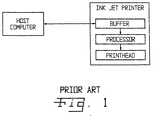
- Ink jet printer 100 includes a processor 104 with an input (not numbered) which is coupled with host computer 102 through buffer 106.
- Processor 104 outputs information to a printhead 108, which in turn uses the information to print an image on a print medium, such as paper.
- Printhead 108 is either movable across or extends in a direction corresponding to a transverse direction or width of the print medium, relative to an advance direction of the print medium. That is, printhead 108 is either mounted on a carriage assembly which is scanned across the width of the print medium in the transverse direction, or is a page-width printhead extending across the width of the print medium.
- Host computer 102 includes an output (not numbered) which is coupled with buffer 106 and processor 104 via conductor 110. Alternatively, host computer 102 may be coupled with buffer 106 and processor 104 using wireless techniques, such as infrared communication. Host computer 102 outputs raster information to processor 104 which corresponds to a plurality of rasters of ink dot placement locations on the print medium in the transverse direction of the print medium, relative to the advance direction.
- the ink is jetted onto the print medium in a plurality of rasters or horizontal lines which are vertically adjacent to each other.
- Each raster includes a plurality of horizontally adjacent ink dot placement locations at which the ink may be jetted from printhead 108 onto the print medium.
- Printhead 108 may be in the form of a multi-color printhead which is used for printing an image on the print medium with a plurality of color inks.
- a multi-color printhead 108 having a plurality of ink jetting heaters 112 is shown.
- Ink jetting heaters 112 are arranged in a plurality of arrays of ink jetting heaters, with each array of ink jetting heaters corresponding to a different color ink to be jetted onto the print medium. More particularly, printhead 108 includes a first array 114 of yellow ink jetting heaters, a second array 116 of magenta ink jetting heaters, and a third array 118 of cyan ink jetting heaters.
- Each array of ink jetting heaters 114, 116 and 118 includes eight ink jetting heaters which are disposed in two horizontally adjacent columns which are staggered relative to each other in the advance direction 122 of paper 120.
- Each ink jetting heater 112 is associated with a corresponding ink jetting orifice (not shown) in printhead 108, through which the different color inks are jetted onto paper 120.
- each array 114, 116 and 118 of ink jetting heaters includes eight ink jetting heaters; however, it will be appreciated that the number and geometric configuration of each array may vary.
- a gap exists between each array 114, 116 and 118 of ink jetting heaters in the paper advance direction 122. In the embodiment shown, the gap corresponds to a distance between two ink jetting heaters 112 within the same column in the advance direction 122. However, it will be appreciated that the actual size of the gap may vary or may be nonexistent.
- Each array 114, 116 and 118 of ink jetting heaters is disposed offset relative to an adjacent array of ink jetting heaters in the advance direction 122.
- the second array 116 of magenta ink jetting heaters is disposed offset relative to the first array 114 of yellow ink jetting heaters.
- the third array 118 of cyan ink jetting heaters is disposed offset relative to the second array 116 of magenta ink jetting heaters.
- the first array 114, second array 116 and third array 118 of ink jetting heaters 112 are disposed substantially in-line relative to each other in the advance direction 122 (i.e., do not overlap relative to each other in the transverse or printhead scan directions 124).
- first array 114, second array 116 and third array 118 of ink jetting heaters 112 may be disposed overlapped relative to each other in other configurations as long as there is an offset between at least two of the arrays of ink jetting heaters in the advance direction 122 of paper 120.
- raster information is transferred from host computer 102 to ink jet printer 100, and thereafter used by ink jet printer 100 for printing during the successive scans of printhead 108.
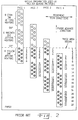
- Fig. 2 is a graphical illustration of how the raster information is used by printer 100 during printing of an image in an image area with successive scans of printhead 108.
- Paper 120 includes an image area 126 in which an image is printed using printhead 108.
- Image area 126 includes a plurality of rasters or horizontal lines which are indicated with index numbers 1-32 at the right hand side of the image area.
- processor 104 When processor 104 receives raster information corresponding to image area 126, paper 120 is advanced in the advance direction 122 until rasters 1-8 of image area 126 substantially align with the eight ink jetting heaters 112 of the first array 114 of ink jetting heaters 112.
- Printhead 108 is scanned across image area 126 during a first pass by moving the carriage assembly in known manner.
- Ink jetting heaters 112 of the first array 114 of ink jetting heaters are selectively actuated as printhead 108 scans across image area 126, such that ink is jetted onto paper 120 at selected locations within image area 126.
- Paper 120 is then moved in the advance direction 122 a distance corresponding to eight rasters such that the first array 114 of yellow ink jetting heaters 112 overlies the next rasters 9-16. Because of the two orifice gap between first array 114 and second array 116, only the first six ink jetting heaters 112 of second array 116 overlie image area 126.
- Printhead 108 is then scanned across image area 126 during a second pass and magenta ink is selectively jetted onto paper 120 in rasters 1 through 6 while yellow ink is selectively jetted onto paper 120 in rasters 9-16 (with the used ink jetting heaters 112 being shown as cross-hatched in pass 2).
- paper 120 is again moved in advance direction 122 a distance corresponding to eight ink jetting heaters 112. Because of the two orifice gap between the second array 116 and third array 118, only the first four cyan ink jetting heaters 112 are used during a third pass of printhead 108 (the used ink jetting heaters 112 being again shown as cross-hatched during pass 3). After the third pass of printhead 108, paper 120 is again moved in the advance direction a distance corresponding to eight ink jetting heaters. As is apparent from Fig. 2, all of the ink jetting heaters 112 in each of the first array 114, second array 116, and third array 118 are used during the fourth scan of printhead 108.
- a steady state condition thereafter occurs in which all of ink jetting heaters 112 are used within image area 126. This steady state condition exists until the first array 114 of ink jetting heaters 112 begins to move out of the bottom of image area 126, at which point the first array 114, second array 116 and third array 118 sequentially advance out of image area 126 and are no longer used.
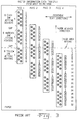
- Fig. 3 is a graphical illustration of a known method of transmitting raster information from a host computer to an ink jet printer for use during successive passes of the printhead 108 across paper 120.
- raster information Prior to a first scan of printhead 108 during a first pass across paper 120, raster information is transferred from the host computer 102 to printer 100 for the first eight rasters of each color to be printed on paper 120. More particularly, raster information for the first eight rasters to be printed by each of the first array 114, second array 116 and third array 118 of ink jetting heaters 112 is transmitted to processor 104 of printer 100.
- the data for the first eight rasters to be printed using the second array 116 and third array 118 must be stored in memory (such as buffer 106 or a separate memory connected with processor 104) for subsequent passes of printhead 108 across paper 120.
- paper 120 is moved in the advance direction 122 a distance corresponding to eight rasters.
- the raster information for the next eight rasters to be printed by each of the first array 114, second array 116 and third array 118 is transmitted from the host computer to the ink jet printer.
- the data for the next eight rasters which is transmitted prior to the second pass of printhead 108 is labeled 9-16 for each of the first array 114, second array 116 and third array 118 in Fig. 2.
- the raster information which is transmitted to printer 100 for the first array 114 corresponds to the actual raster information which is used during the second pass of the printhead (note that the raster information actually used during the second pass for actuating first array 114 of the ink jetting heaters 112 is the same in Figs. 2 and 3). However, it is also apparent that the raster information which is transmitted to printer 100 prior to the second pass of the printhead for the second array 116 of magenta ink jetting heaters 112 (see Fig. 3) does not correspond to the raster information which is actually used during the second pass of the printhead 108 (see Fig. 2).
- the raster information for second array 116 associated with rasters 9-16 is stored in memory and the raster information for rasters 1-6 is retrieved from memory and used during the second pass of printhead 108.
- the raster information for the third array 118 of cyan ink jetting heaters 112 is not used during the second pass of the printhead and must also be stored in memory for later use.
- ink jet printer 100 For each subsequent pass of printhead 108, raster information for the next eight rasters is transmitted to processor 104 of printer 100 for each of the first array 114, second array 116 and third array 118, even though some of the raster information is not used during the next pass of the printhead. Accordingly, with known methods, ink jet printer 100 must have enough memory to store 8 + 2 + 8 + 2 + 8 cyan rasters, 8 + 2 + 8 magenta rasters and 8 yellow rasters, for a total of 54 rasters (where the integer 8 represents raster information to be used during a subsequent pass and the integer 2 represents raster information associated with an adjacent two orifice gap).
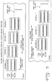
- Fig. 4 illustrates one embodiment of the present invention for reducing memory requirements in printer 100 by transmitting raster information to processor 104 which is used during a next pass of printhead 108.
- processor 104 Prior to a first pass of printhead 108, only raster information for the first eight rasters to be printed by the first array 114 are transmitted from host computer 102 to processor 104.
- Raster information to be used for actuating the second array 116 and third array 118 during subsequent passes of printhead 108 is not transmitted to processor 104 prior to pass 1. Rather, only the raster information which is to be used during the first pass of printhead 108 is transmitted to electrical processor 104.
- the next eight rasters to be printed with the first array 114 i.e., rasters 9-16
- the first six rasters to be printed with the second array 116 i.e., rasters 1-6
- the first pass of printhead 108 only raster information which is used during the second pass of printhead 108 is transmitted from host computer 102 to printer 100. It is therefore unnecessary to store raster information transmitted immediately prior to the second pass of printhead 108 for use during subsequent passes of printhead 108 across paper 120.
- Fig. 5 there is shown a graphical illustration of raster information used by an ink jet printer having a page-width printhead 128 during consecutive advances of paper 120 in the advance direction 122.
- printhead 128 is shown with only eight ink jetting heaters 112 corresponding to eight ink dot placement locations on paper 120.
- printhead 128 actually includes a number of ink jetting heaters 112 which is dependent upon the resolution of the printer and the width of the image area 126 on paper 120.
- each of a first array 130, second array 132 and third array 134 would include approximately 2400 ink jetting heaters 112.
- scan directions 124 correspond to an effective scanning when the ink jetting heaters 112 in each of the rows 130, 132, and 134 are sequentially actuated. It is to be understood, however, that such effective scanning may be eliminated if desired, by the simultaneous actuation of the ink jetting heaters 112.
- raster information for a first array 130 of yellow ink jetting heaters 112 is transmitted from host computer 102 to the printer.
- Paper 120 is moved in the advance direction 122 until the first array 130 overlies raster 1 of image area 126.
- the yellow ink jetting heaters 112 in the first array 130 are then selectively energized to jet yellow ink onto the first raster at selected locations.
- the paper is then moved in the advance direction 122 a distance corresponding to one raster. Yellow ink is then selectively placed on raster 2 using the first array 130 of ink jetting heaters.
- Paper 120 is again moved in the advance direction 122 a distance corresponding to one raster and yellow ink is jetted onto raster 3. Paper 120 is then again moved in the advance direction 122 a distance corresponding to one raster.
- first array 130 of yellow ink jetting heaters 112 overlies raster 4
- second array 132 of magenta ink jetting heaters 112 overlies raster 1. Yellow ink is then placed at selected ink dot locations in raster 4, and magenta ink is placed at selected ink dot placement locations in raster 1.
- first array 130 With the fifth advance of paper 120, first array 130 overlies raster 5 and second array 132 overlies raster 2; and with the sixth advance of paper 120, the first array 130 overlies raster 6 and the second array 132 overlies raster 3.
- a steady state condition occurs in which all three of the first array 130, second array 132 and third array 134 overlie corresponding rasters within image area 126. This steady state condition exists until the ink jetting heaters 112 begin to move out of the bottom of image area 126 on paper 120.
- raster information for raster 1 to be printed by each of the first array 130, second array 132 and third array 134 is transmitted from host computer 102 to the printer prior to jetting the yellow ink onto raster 1 associated with advance 1 of paper 120.
- the first raster to be printed by the second array 132 and third array 134 must therefore be stored in memory for use during a subsequent jetting of ink jetting heaters 112 associated with a particular advance of paper 120.
- the raster information associated with all of the ink jetting heaters which are not shown as cross-hatched in Fig. 5 for a particular advance of paper 120 must be stored in a memory (such as buffer 106) of printer 100.
- the printer must therefore have enough memory capacity to store 1 + 2 + 1 + 2 + 1 cyan rasters, and 1 + 2 + 1 magenta rasters, and one yellow raster, for a total of 12 rasters.
- a maximum of only three rasters must be stored by a memory within the printer. That is, during a steady state condition, only three rasters of information are transmitted from host computer 102 to the printer, and only three rasters of information are printed in associated actuation of the ink jetting heaters within the first array 130, second array 132 and third array 134 of printhead 128.
- the present invention therefore also reduces memory requirements within the printer when used in conjunction with a page-width printhead 128.
Landscapes
- Physics & Mathematics (AREA)
- Engineering & Computer Science (AREA)
- Mathematical Physics (AREA)
- General Engineering & Computer Science (AREA)
- General Physics & Mathematics (AREA)
- Theoretical Computer Science (AREA)
- Ink Jet (AREA)
- Record Information Processing For Printing (AREA)
Applications Claiming Priority (2)
| Application Number | Priority Date | Filing Date | Title |
|---|---|---|---|
| US08/868,694 US6092888A (en) | 1997-06-04 | 1997-06-04 | Method of transmitting raster information from a host computer to an ink jet printer and corresponding method of printing |
| US868694 | 1997-06-04 |
Publications (2)
| Publication Number | Publication Date |
|---|---|
| EP0883082A2 true EP0883082A2 (de) | 1998-12-09 |
| EP0883082A3 EP0883082A3 (de) | 2002-10-16 |
Family
ID=25352156
Family Applications (1)
| Application Number | Title | Priority Date | Filing Date |
|---|---|---|---|
| EP98109592A Withdrawn EP0883082A3 (de) | 1997-06-04 | 1998-05-27 | Verfahren zur Übertragung von Rasterinformation von einem Hauptrechner zu einem Tintenstrahldrucker, und entsprechendes Druckverfahren |
Country Status (6)
| Country | Link |
|---|---|
| US (1) | US6092888A (de) |
| EP (1) | EP0883082A3 (de) |
| JP (1) | JPH1195945A (de) |
| KR (1) | KR19990006627A (de) |
| CN (1) | CN1115624C (de) |
| TW (1) | TW402565B (de) |
Cited By (1)
| Publication number | Priority date | Publication date | Assignee | Title |
|---|---|---|---|---|
| EP1087348A3 (de) * | 1999-09-22 | 2003-01-02 | Continental Express Money Order Company Inc. | Verfahren und Vorrichtung zum Vorbereiten und zur Ausgabe von Dokumenten |
Families Citing this family (7)
| Publication number | Priority date | Publication date | Assignee | Title |
|---|---|---|---|---|
| US6724895B1 (en) | 1998-06-18 | 2004-04-20 | Supersensor (Proprietary) Limited | Electronic identification system and method with source authenticity verification |
| US7137000B2 (en) * | 2001-08-24 | 2006-11-14 | Zih Corp. | Method and apparatus for article authentication |
| US6969134B2 (en) * | 2001-10-01 | 2005-11-29 | Zih Corp. | Printer or other media processor with on-demand selective media converter |
| US20030061947A1 (en) * | 2001-10-01 | 2003-04-03 | Hohberger Clive P. | Method and apparatus for associating on demand certain selected media and value-adding elements |
| JP4217180B2 (ja) * | 2004-03-17 | 2009-01-28 | 大日本印刷株式会社 | 熱転写シートに積層されたホログラム又は回折格子の転写方法、並びに被転写媒体 |
| US20090079774A1 (en) * | 2007-09-24 | 2009-03-26 | Stephenson Iii Stanley W | Motion compensation for monolithic inkjet head |
| WO2018218630A1 (zh) * | 2017-06-02 | 2018-12-06 | 北京美科艺数码科技发展有限公司 | 一种喷墨打印方法 |
Family Cites Families (13)
| Publication number | Priority date | Publication date | Assignee | Title |
|---|---|---|---|---|
| US4059183A (en) * | 1976-12-30 | 1977-11-22 | International Business Machines Corporation | Dot matrix printer with slanted print head and modular skewing of dot pattern information |
| JPS6353045A (ja) * | 1986-08-25 | 1988-03-07 | Canon Inc | 画像記録装置 |
| DE3885945T2 (de) * | 1987-06-24 | 1994-06-30 | Canon Kk | Farbdrucker. |
| US5351074A (en) * | 1988-01-19 | 1994-09-27 | Canon Kabushiki Kaisha | Apparatus for forming a color image using two memories |
| JPH01234248A (ja) * | 1988-03-15 | 1989-09-19 | Canon Inc | 2色プリンタ |
| US4953104A (en) * | 1989-05-18 | 1990-08-28 | Eastman Kodak Company | Page buffer for an electronic gray-scale color printer |
| US5003494A (en) * | 1989-12-18 | 1991-03-26 | Eastman Kodak Company | Data storage system for an electronic color printer |
| KR940007012B1 (ko) * | 1991-02-13 | 1994-08-03 | 삼성전자 주식회사 | 칼라비디오프린터의고속프린팅방법및장치 |
| US5490237A (en) * | 1993-04-26 | 1996-02-06 | Hewlett-Packard Company | Page printer having improved system for receiving and printing raster pixel image data from a host computer |
| US5450532A (en) * | 1993-04-29 | 1995-09-12 | Hewlett-Packard Company | Cache memory system for a color ink jet printer |
| US5577172A (en) * | 1994-07-01 | 1996-11-19 | Lasermaster Corporation | High-capacity protocol for packet-based networks |
| DE69533937T2 (de) * | 1994-11-17 | 2005-06-30 | Canon K.K. | Übertragung von verschobenen Daten auf einen Farbdrucker |
| US5654744A (en) * | 1995-03-06 | 1997-08-05 | Hewlett-Packard Company | Simultaneously printing with different sections of printheads for improved print quality |
-
1997
- 1997-06-04 US US08/868,694 patent/US6092888A/en not_active Expired - Lifetime
-
1998
- 1998-05-27 EP EP98109592A patent/EP0883082A3/de not_active Withdrawn
- 1998-06-03 KR KR1019980020547A patent/KR19990006627A/ko not_active Withdrawn
- 1998-06-03 CN CN98109638.7A patent/CN1115624C/zh not_active Expired - Fee Related
- 1998-06-03 JP JP10190915A patent/JPH1195945A/ja not_active Abandoned
- 1998-07-24 TW TW087108860A patent/TW402565B/zh not_active IP Right Cessation
Cited By (2)
| Publication number | Priority date | Publication date | Assignee | Title |
|---|---|---|---|---|
| EP1087348A3 (de) * | 1999-09-22 | 2003-01-02 | Continental Express Money Order Company Inc. | Verfahren und Vorrichtung zum Vorbereiten und zur Ausgabe von Dokumenten |
| US6864990B1 (en) | 1999-09-22 | 2005-03-08 | Continental Express Money Order Company, Inc. | Method and machine for preparing and dispensing documents |
Also Published As
| Publication number | Publication date |
|---|---|
| KR19990006627A (ko) | 1999-01-25 |
| CN1201178A (zh) | 1998-12-09 |
| CN1115624C (zh) | 2003-07-23 |
| US6092888A (en) | 2000-07-25 |
| EP0883082A3 (de) | 2002-10-16 |
| TW402565B (en) | 2000-08-21 |
| JPH1195945A (ja) | 1999-04-09 |
Similar Documents
| Publication | Publication Date | Title |
|---|---|---|
| EP1953681B1 (de) | Druckkopf, Druckkopfsteuerungsverfahren, und Datenausgabegerät | |
| US6923521B2 (en) | Subcovered printing mode for a printhead with multiple sized ejectors | |
| JPH07205541A (ja) | カラーインクジェット記録方法 | |
| US20020109752A1 (en) | Printing using a print head with staggered nozzle arrangements | |
| US7758154B2 (en) | Inkjet printing apparatus and inkjet printing method | |
| US6217150B1 (en) | Method of printing with an ink jet printer using multiple carriage speeds | |
| EP0703086B1 (de) | Druckgerät und -verfahren mit logischem Stromkreis um die Eingangsrate von Videodaten zu reduzieren | |
| JP2002166578A (ja) | インクジェット記録方法およびインクジェット記録装置 | |
| US6092888A (en) | Method of transmitting raster information from a host computer to an ink jet printer and corresponding method of printing | |
| JPH09164706A (ja) | インクジェットヘッド | |
| US6409299B1 (en) | Printing apparatus and printing method | |
| US7315393B2 (en) | Printing system, printer driver, and printing method | |
| EP0593283B1 (de) | Bild-Druckverfahren und Vorrichtung dafür | |
| US7126715B2 (en) | Ink jet recording apparatus and control method therefor | |
| US6154233A (en) | System and method for separating raster data for printing | |
| US5959646A (en) | Method of printing with an ink jet printer using independent shingling on a raster by raster basis | |
| EP0855278A2 (de) | Drucken unter Verwendung eines Tintenstrahldruckers | |
| JP3613076B2 (ja) | 画像処理装置、画像処理方法、および記録媒体 | |
| JP2001146032A (ja) | 縦配列ヘッドを用いたカラー印刷 | |
| JP2004209989A (ja) | 印刷装置、印刷方法および記録媒体 | |
| JP3596313B2 (ja) | 印刷装置、印刷方法および記録媒体 | |
| JP2013212659A (ja) | 印刷装置、印刷方法 | |
| US5999705A (en) | Method of interlaced printing using an ink jet printer | |
| JPH09187924A (ja) | 記録方法及び記録装置並びに記録システム | |
| JP2013212635A (ja) | 印刷装置、印刷方法 |
Legal Events
| Date | Code | Title | Description |
|---|---|---|---|
| PUAI | Public reference made under article 153(3) epc to a published international application that has entered the european phase |
Free format text: ORIGINAL CODE: 0009012 |
|
| AK | Designated contracting states |
Kind code of ref document: A2 Designated state(s): AT BE CH CY DE DK ES FI FR GB GR IE IT LI LU MC NL PT SE |
|
| AX | Request for extension of the european patent |
Free format text: AL;LT;LV;MK;RO;SI |
|
| PUAL | Search report despatched |
Free format text: ORIGINAL CODE: 0009013 |
|
| AK | Designated contracting states |
Kind code of ref document: A3 Designated state(s): AT BE CH CY DE DK ES FI FR GB GR IE IT LI LU MC NL PT SE |
|
| AX | Request for extension of the european patent |
Free format text: AL;LT;LV;MK;RO;SI |
|
| 17P | Request for examination filed |
Effective date: 20030403 |
|
| AKX | Designation fees paid |
Designated state(s): DE FR GB |
|
| 17Q | First examination report despatched |
Effective date: 20040524 |
|
| STAA | Information on the status of an ep patent application or granted ep patent |
Free format text: STATUS: THE APPLICATION HAS BEEN WITHDRAWN |
|
| 18W | Application withdrawn |
Effective date: 20050506 |