EP0881021B1 - Schaftfräser - Google Patents
Schaftfräser Download PDFInfo
- Publication number
- EP0881021B1 EP0881021B1 EP98108203A EP98108203A EP0881021B1 EP 0881021 B1 EP0881021 B1 EP 0881021B1 EP 98108203 A EP98108203 A EP 98108203A EP 98108203 A EP98108203 A EP 98108203A EP 0881021 B1 EP0881021 B1 EP 0881021B1
- Authority
- EP
- European Patent Office
- Prior art keywords
- clamping
- plate
- milling cutter
- cutting
- clamping plate
- Prior art date
- Legal status (The legal status is an assumption and is not a legal conclusion. Google has not performed a legal analysis and makes no representation as to the accuracy of the status listed.)
- Expired - Lifetime
Links
Images
Classifications
-
- B—PERFORMING OPERATIONS; TRANSPORTING
- B23—MACHINE TOOLS; METAL-WORKING NOT OTHERWISE PROVIDED FOR
- B23C—MILLING
- B23C5/00—Milling-cutters
- B23C5/16—Milling-cutters characterised by physical features other than shape
- B23C5/20—Milling-cutters characterised by physical features other than shape with removable cutter bits or teeth or cutting inserts
- B23C5/22—Securing arrangements for bits or teeth or cutting inserts
- B23C5/2239—Securing arrangements for bits or teeth or cutting inserts with cutting inserts clamped by a clamping member acting almost perpendicular on the cutting face
- B23C5/2243—Securing arrangements for bits or teeth or cutting inserts with cutting inserts clamped by a clamping member acting almost perpendicular on the cutting face for plate-like cutting inserts
-
- B—PERFORMING OPERATIONS; TRANSPORTING
- B23—MACHINE TOOLS; METAL-WORKING NOT OTHERWISE PROVIDED FOR
- B23C—MILLING
- B23C5/00—Milling-cutters
- B23C5/02—Milling-cutters characterised by the shape of the cutter
- B23C5/10—Shank-type cutters, i.e. with an integral shaft
- B23C5/109—Shank-type cutters, i.e. with an integral shaft with removable cutting inserts
-
- B—PERFORMING OPERATIONS; TRANSPORTING
- B23—MACHINE TOOLS; METAL-WORKING NOT OTHERWISE PROVIDED FOR
- B23C—MILLING
- B23C2200/00—Details of milling cutting inserts
- B23C2200/04—Overall shape
- B23C2200/045—Round
-
- Y—GENERAL TAGGING OF NEW TECHNOLOGICAL DEVELOPMENTS; GENERAL TAGGING OF CROSS-SECTIONAL TECHNOLOGIES SPANNING OVER SEVERAL SECTIONS OF THE IPC; TECHNICAL SUBJECTS COVERED BY FORMER USPC CROSS-REFERENCE ART COLLECTIONS [XRACs] AND DIGESTS
- Y10—TECHNICAL SUBJECTS COVERED BY FORMER USPC
- Y10T—TECHNICAL SUBJECTS COVERED BY FORMER US CLASSIFICATION
- Y10T407/00—Cutters, for shaping
- Y10T407/19—Rotary cutting tool
- Y10T407/1906—Rotary cutting tool including holder [i.e., head] having seat for inserted tool
- Y10T407/1908—Face or end mill
- Y10T407/192—Face or end mill with separate means to fasten tool to holder
-
- Y—GENERAL TAGGING OF NEW TECHNOLOGICAL DEVELOPMENTS; GENERAL TAGGING OF CROSS-SECTIONAL TECHNOLOGIES SPANNING OVER SEVERAL SECTIONS OF THE IPC; TECHNICAL SUBJECTS COVERED BY FORMER USPC CROSS-REFERENCE ART COLLECTIONS [XRACs] AND DIGESTS
- Y10—TECHNICAL SUBJECTS COVERED BY FORMER USPC
- Y10T—TECHNICAL SUBJECTS COVERED BY FORMER US CLASSIFICATION
- Y10T407/00—Cutters, for shaping
- Y10T407/19—Rotary cutting tool
- Y10T407/1906—Rotary cutting tool including holder [i.e., head] having seat for inserted tool
- Y10T407/1908—Face or end mill
- Y10T407/1924—Specified tool shape
-
- Y—GENERAL TAGGING OF NEW TECHNOLOGICAL DEVELOPMENTS; GENERAL TAGGING OF CROSS-SECTIONAL TECHNOLOGIES SPANNING OVER SEVERAL SECTIONS OF THE IPC; TECHNICAL SUBJECTS COVERED BY FORMER USPC CROSS-REFERENCE ART COLLECTIONS [XRACs] AND DIGESTS
- Y10—TECHNICAL SUBJECTS COVERED BY FORMER USPC
- Y10T—TECHNICAL SUBJECTS COVERED BY FORMER US CLASSIFICATION
- Y10T407/00—Cutters, for shaping
- Y10T407/19—Rotary cutting tool
- Y10T407/1946—Face or end mill
- Y10T407/1948—Face or end mill with cutting edge entirely across end of tool [e.g., router bit, end mill, etc.]
-
- Y—GENERAL TAGGING OF NEW TECHNOLOGICAL DEVELOPMENTS; GENERAL TAGGING OF CROSS-SECTIONAL TECHNOLOGIES SPANNING OVER SEVERAL SECTIONS OF THE IPC; TECHNICAL SUBJECTS COVERED BY FORMER USPC CROSS-REFERENCE ART COLLECTIONS [XRACs] AND DIGESTS
- Y10—TECHNICAL SUBJECTS COVERED BY FORMER USPC
- Y10T—TECHNICAL SUBJECTS COVERED BY FORMER US CLASSIFICATION
- Y10T407/00—Cutters, for shaping
- Y10T407/21—Arc segment tool
Definitions
- the invention relates to an end mill.
- Milling cutters come in numerous designs known. You will, for example, in manufacturing used by molds. Often there will be End mills used in which at least one insert, which usually has a circular contour, is attached to the free end is. It has also become known, two or more Arrange the inserts in the circumferential distance.
- Such inserts are mostly with the help of Tensioning screws attached to the shaft.
- the shaft has one Insert on with a threaded hole, and the inserts are provided with a through-hole for the passage a clamping screw.
- Such fixation the insert is in itself satisfactory, bumps however, problems arise when the dimensions of the inserts to fall below a lower level.
- the diameter of the Through holes become smaller as the inserts become smaller naturally smaller. Accordingly, they also reduce the dimensions of the clamping screw. Because the turnbuckles mostly have an inner polygon on the head of these dimensions where it is very easy to get one Spinning comes. It is therefore difficult to insert the inserts to loosen or attach satisfactorily without damaging the screw
- the invention is therefore based on the object To create end mills for two inserts that are effectively releasably attachable without any handling difficulties arise.
- a clamping plate is provided, which can be tensioned using a single clamping screw.
- One end of the clamping plate is supported on the shaft and has at the other end two clamping sections, from which one with the front of a cutting plate and the other with the back of the other insert in Intervention is.
- the clamping section of the clamping plate, the against the back of the other insert rests designed as a seat for this insert.
- the only clamping screw is outside the contour of the inserts and can therefore be used with an appropriate Diameter. It is therefore possible with the help of the clamping plates, both cutting plates are effective to be determined.
- the sufficiently large to be dimensioned Clamping screw can therefore also be effective from a tool captured and released or attracted.
- the attachment of the inserts according to the invention is not dependent on the fact that they are arranged diametrically. However, an arrangement of the cutting plates is preferred at least parallel to each other, so that the clamping plate at least in two parallel planes with the facing one Insert can engage.
- chip recesses for the removal of chips.
- one in the shaft for example on the end face, while another chip recess in the clamping section of the Clamping plate is formed, which with the front of the Cutting plate interacts.
- the clamping screw preferably has a conical head, the one with a conical bore section of the clamping plate cooperates.
- the head of the clamping screw preferably has an internal polygon, preferably an internal hexagon to be operated with a tool.
- the shaft has a threaded hole with which the clamping screw cooperates.
- the Threaded hole an offset to the fitting hole in the clamping plate from e.g. 0.2 mm. Over the conical head the screw, the clamping plate against one end pressed the shaft.
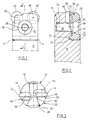
- a shaft which is circular in cross section 10 of an end mill shown at the free end has a recess 12.
- the recess has a first one Surface 14 transverse to the longitudinal axis of the shaft 10 and a second surface 16 which is substantially parallel to the longitudinal axis runs.
- a threaded hole 18 molded, the axis of which is perpendicular to the longitudinal axis of the shaft.
- a clamping plate 20 is received by the recess 12, whose outer contour is shaped so that it the contour of Shaft 10 supplemented in the area of the recess, i.e. at the Outside is essentially circular arc and after rounded up to the free end of the shaft, as in particular emerges from Fig. 2.
- the clamping plate has 20 on a transversely extending strip 22, the with little play in a suitably shaped Recess 24 sits in the surface 16. This is the Clamping plate kept oriented in its position. In this Location is a through hole 26 of the clamping plate 20 for tapping 18 aligned or is a small offset provided to generate a bias for the clamping plate.
- the through hole 26 has a conical section 28 and a cylindrical portion 30.
- the piercing 26 receives a clamping screw 32, the shaft 34 is seated in the threaded bore 18 and its conical head 36 cooperates with the conical bore section 28. How 1, the head 36 has a hexagon socket 38 on.
- the clamping plate 20 with the help the only clamping screw 32 clamping against the cutting plates 40, 42 pressed.
- the clamping screw 32 is located outside the outer contour of the cutting plates 40, 42 and can therefore have a sufficient diameter or the head can be chosen large enough to get an appropriately dimensioned polygon for an effective engagement of a tool.
- On another advantage is that for loosening or the setting of two inserts only one Screw is required, which reduces the time required.
Landscapes
- Engineering & Computer Science (AREA)
- Mechanical Engineering (AREA)
- Milling Processes (AREA)
- Apparatuses For Bulk Treatment Of Fruits And Vegetables And Apparatuses For Preparing Feeds (AREA)
- Cutting Tools, Boring Holders, And Turrets (AREA)
Description
- Fig. 1
- zeigt eine Seitenansicht eines Schaftfräsers nach der Erfindung.
- Fig. 2
- zeigt einen Schnitt durch die Darstellung nach Fig. 1 entlang der Linie 2-2.
- Fig. 3
- zeigt eine Draufsicht auf den Schaftfräser nach Fig. 1.
Claims (7)
- Schaftfräser mitzwei Schneidplatten (40, 42), die in Umfangsrichtung versetzt am Schaft angeordnet sind,einer Klemmplatte (20), die in einer Ausnehmung (12) des Schaftes (10) angeordnet und mittels einer einzigen Klemmschraube (32) mit einem Ende gegen eine zugeordnete Wand (16) der Ausnehmung (12) und mit dem anderen Ende gegen beide Schneidplatten (40, 42) anpreßbar ist,wobei ein Klemmabschnitt (50) der Klemmplatte (20) gegen die Vorderseite einer Schneidplatte (40) und ein anderer Klemmabschnitt (48) gegen die Rückseite der anderen Klemmplatte (42) anliegt undwobei der Klemmabschnitt (48) der Klemmplatte (20), der gegen die Rückseite der anderen Schneidplatte (42) anliegt, als Sitz für diese Schneidplatte (42) ausgebildet ist.
- Schaftfräser nach Anspruch 1, dadurch gekennzeichnet, daß die Schneidplatten (40, 42) auf einem Durchmesser des Schaftes (10) oder auf einer Achse parallel zu einem Durchmesser angeordnet sind.
- Schaftfräser nach Anspruch 1 oder 2, dadurch gekennzeichnet, daß die Klemmplatte (20) im Bereich des an der Vorderseite der Schneidplatte (40) anliegenden Klemmabschnitts (50) eine Spanmulde (56) aufweist.
- Schaftfräser nach einem der Ansprüche 1 bis 3, dadurch gekennzeichnet, daß die Klemmschraube (32) einen konischen Kopf (36) aufweist, der mit einem konischen Bohrungsabschnitt (28) der Klemmplatte (20) zusammenwirkt.
- Schaftfräser nach einem der Ansprüche 1 bis 4, dadurch gekennzeichnet, daß der Kopf (36) der Klemmschraube (32) einen Innenmehrkant (38) für ein Spannwerkzeug aufweist.
- Schaftfräser nach einem der Ansprüche 1 bis 5, dadurch gekennzeichnet, daß die Klemmabschnitte (48, 50) der Klemmplatte (20) mit einer Mulde der jeweiligen Schneidplatte zusammenwirken.
- Schaftfräser nach einem der Ansprüche 1 bis 6, dadurch gekennzeichnet, daß die Klemmschraube mit einer Gewindebohrung (18) im Schaft (10) zusammenwirkt.
Applications Claiming Priority (2)
| Application Number | Priority Date | Filing Date | Title |
|---|---|---|---|
| DE19721900 | 1997-05-26 | ||
| DE19721900A DE19721900C2 (de) | 1997-05-26 | 1997-05-26 | Schaftfräser |
Publications (2)
| Publication Number | Publication Date |
|---|---|
| EP0881021A1 EP0881021A1 (de) | 1998-12-02 |
| EP0881021B1 true EP0881021B1 (de) | 2001-11-28 |
Family
ID=7830481
Family Applications (1)
| Application Number | Title | Priority Date | Filing Date |
|---|---|---|---|
| EP98108203A Expired - Lifetime EP0881021B1 (de) | 1997-05-26 | 1998-05-06 | Schaftfräser |
Country Status (4)
| Country | Link |
|---|---|
| US (1) | US6146059A (de) |
| EP (1) | EP0881021B1 (de) |
| DE (2) | DE19721900C2 (de) |
| ES (1) | ES2167037T3 (de) |
Families Citing this family (4)
| Publication number | Priority date | Publication date | Assignee | Title |
|---|---|---|---|---|
| DE19928840C1 (de) | 1999-06-24 | 2000-11-16 | Actech Gmbh Adv Casting Tech | Schaftwerkzeug mit fest angeordneten flügelartigen Einsätzen |
| US9199315B2 (en) | 2000-06-02 | 2015-12-01 | Kennametal Inc. | Twist drill and method for producing a twist drill which method includes forming a flute of a twist drill |
| DE10242191B4 (de) * | 2001-09-27 | 2009-02-05 | Actech Gmbh | Verfahren für die Herstellung von hitzebeständigen Gießformen |
| SE526105C2 (sv) * | 2003-02-06 | 2005-07-05 | Seco Tools Ab | Fräs med tre konvext krökta skäreggar betning |
Family Cites Families (15)
| Publication number | Priority date | Publication date | Assignee | Title |
|---|---|---|---|---|
| US3125799A (en) * | 1964-03-24 | Tool holder for indexable cutting inserts | ||
| US1071479A (en) * | 1913-06-02 | 1913-08-26 | William T Strudwick | Milling-tool. |
| US1822176A (en) * | 1930-05-03 | 1931-09-08 | Ingersoll Milling Machine Co | Method of producing metal working tools |
| US3646650A (en) * | 1969-12-30 | 1972-03-07 | Valeron Corp | Milling cutter construction |
| DE7831988U1 (de) * | 1978-10-27 | 1980-04-03 | Komet Stahlhalter- Und Werkzeugfabrik Robert Breuning Gmbh, 7122 Besigheim | Klemmvorrichtung zur klemmung einer wendeschneidplatte an einem werkzeughalter |
| WO1980002812A1 (en) * | 1979-06-19 | 1980-12-24 | Sandvik Ab | Milling cutter |
| ATE5640T1 (de) * | 1980-06-12 | 1984-01-15 | Black & Decker Inc. | Schneidmessermontage fuer eine kraftangetriebene hobelmaschine. |
| US4487532A (en) * | 1982-09-07 | 1984-12-11 | Hamilton Martin N | Conical wedge lock for cutter blade |
| US4525110A (en) * | 1983-05-18 | 1985-06-25 | Stojan Stojanovski | Indexable ball nose end mill |
| DE4127509A1 (de) * | 1990-10-09 | 1992-04-16 | Deitert Heinz | Fingerfraeser |
| DE4034345C1 (de) * | 1990-10-29 | 1991-08-29 | Mapal Fabrik Fuer Praezisionswerkzeuge Dr. Kress Kg, 7080 Aalen, De | |
| DE4312401A1 (de) * | 1993-04-16 | 1994-10-20 | Widia Heinlein Gmbh | Schneidplatte |
| US5863157A (en) * | 1996-03-13 | 1999-01-26 | Ryoco Seiki Co., Ltd. | Throwaway ball end mill |
| DE19624342C1 (de) * | 1996-06-19 | 1997-12-11 | Walter Ag | Schneidplatte und Fräser, insbesondere Kugelstirnfräser oder Kopierfräser |
| KR100187562B1 (ko) * | 1996-08-21 | 1999-06-01 | 최효병 | 정삭용 쓰로어웨이 볼 앤드밀 |
-
1997
- 1997-05-26 DE DE19721900A patent/DE19721900C2/de not_active Expired - Fee Related
-
1998
- 1998-05-06 DE DE59802202T patent/DE59802202D1/de not_active Expired - Fee Related
- 1998-05-06 ES ES98108203T patent/ES2167037T3/es not_active Expired - Lifetime
- 1998-05-06 EP EP98108203A patent/EP0881021B1/de not_active Expired - Lifetime
- 1998-05-18 US US09/080,706 patent/US6146059A/en not_active Expired - Fee Related
Also Published As
| Publication number | Publication date |
|---|---|
| EP0881021A1 (de) | 1998-12-02 |
| DE19721900A1 (de) | 1998-12-03 |
| DE59802202D1 (de) | 2002-01-10 |
| DE19721900C2 (de) | 1999-04-15 |
| US6146059A (en) | 2000-11-14 |
| ES2167037T3 (es) | 2002-05-01 |
Similar Documents
| Publication | Publication Date | Title |
|---|---|---|
| DE60031297T2 (de) | Schneidkopf und werkzeugkörperzusammenbau | |
| DE19624685C1 (de) | Rundstabmesser und insbesondere dafür vorgesehener Messerkopf | |
| DE10326928B4 (de) | Schnittstelle zwischen zwei Teilelementen eines Werkzeugsystems | |
| DE3448086C2 (de) | ||
| DE3321184C2 (de) | Drehwerkzeug mit einem Halter für einen auswechselbaren Schneideinsatz | |
| DE69736114T2 (de) | Schneidwerkzeug zusammenbau | |
| DE102007030876B4 (de) | Werkzeug zur spanabtragenden Bearbeitung von Werkstücken | |
| DE2619736A1 (de) | Hobel | |
| EP3223983B1 (de) | Werkzeug für die zerspanende bearbeitung | |
| DE60128943T2 (de) | Schlüssel zum montieren und ausbauen eines schneideinsatzes | |
| DE2164093C3 (de) | Schneidwerkzeug | |
| DE4330484C2 (de) | Schälwälzfräser | |
| DE4200096C2 (de) | Vorrichtung zum Verschließen einer Öffnung in einer Verkleidung | |
| DE10222048A1 (de) | Werkzeug und Verfahren zur Maschinenbearbeitung von Werkstücken | |
| DE4028353A1 (de) | Werkzeughalter | |
| DE19721900C2 (de) | Schaftfräser | |
| EP0940227B1 (de) | Werkzeug zum Vernieten von Blindnietmuttern | |
| DE2736387C2 (de) | Zerspanungswerkzeug | |
| DE3511580C2 (de) | ||
| DE3211460A1 (de) | Zerspanungswerkzeug | |
| DE60304293T2 (de) | Sprühfeuchtwerk | |
| DE102005051545B4 (de) | Werkzeughalter | |
| DE2117709C3 (de) | Schneideinsatz und zugehöriger Klemmhalter | |
| DE10308036B4 (de) | Kugelkopierfräser | |
| DE202004007811U1 (de) | Werkzeug zur spanabtragenden Bearbeitung von Werkstücken |
Legal Events
| Date | Code | Title | Description |
|---|---|---|---|
| PUAI | Public reference made under article 153(3) epc to a published international application that has entered the european phase |
Free format text: ORIGINAL CODE: 0009012 |
|
| AK | Designated contracting states |
Kind code of ref document: A1 Designated state(s): CH DE ES FR GB IT LI NL SE |
|
| AX | Request for extension of the european patent |
Free format text: AL;LT;LV;MK;RO;SI |
|
| 17P | Request for examination filed |
Effective date: 19981117 |
|
| AKX | Designation fees paid |
Free format text: CH DE ES FR GB IT LI NL SE |
|
| 17Q | First examination report despatched |
Effective date: 19991020 |
|
| GRAG | Despatch of communication of intention to grant |
Free format text: ORIGINAL CODE: EPIDOS AGRA |
|
| GRAG | Despatch of communication of intention to grant |
Free format text: ORIGINAL CODE: EPIDOS AGRA |
|
| GRAH | Despatch of communication of intention to grant a patent |
Free format text: ORIGINAL CODE: EPIDOS IGRA |
|
| GRAH | Despatch of communication of intention to grant a patent |
Free format text: ORIGINAL CODE: EPIDOS IGRA |
|
| GRAA | (expected) grant |
Free format text: ORIGINAL CODE: 0009210 |
|
| AK | Designated contracting states |
Kind code of ref document: B1 Designated state(s): CH DE ES FR GB IT LI NL SE |
|
| REG | Reference to a national code |
Ref country code: CH Ref legal event code: EP |
|
| REG | Reference to a national code |
Ref country code: CH Ref legal event code: NV Representative=s name: ISLER & PEDRAZZINI AG |
|
| REG | Reference to a national code |
Ref country code: GB Ref legal event code: IF02 |
|
| REF | Corresponds to: |
Ref document number: 59802202 Country of ref document: DE Date of ref document: 20020110 |
|
| GBT | Gb: translation of ep patent filed (gb section 77(6)(a)/1977) |
Effective date: 20020307 |
|
| REG | Reference to a national code |
Ref country code: ES Ref legal event code: FG2A Ref document number: 2167037 Country of ref document: ES Kind code of ref document: T3 |
|
| ET | Fr: translation filed | ||
| RAP2 | Party data changed (patent owner data changed or rights of a patent transferred) |
Owner name: FETTE GMBH |
|
| NLT2 | Nl: modifications (of names), taken from the european patent patent bulletin |
Owner name: FETTE GMBH |
|
| PLBE | No opposition filed within time limit |
Free format text: ORIGINAL CODE: 0009261 |
|
| STAA | Information on the status of an ep patent application or granted ep patent |
Free format text: STATUS: NO OPPOSITION FILED WITHIN TIME LIMIT |
|
| 26N | No opposition filed | ||
| NLT1 | Nl: modifications of names registered in virtue of documents presented to the patent office pursuant to art. 16 a, paragraph 1 |
Owner name: FETTE GMBH |
|
| PGFP | Annual fee paid to national office [announced via postgrant information from national office to epo] |
Ref country code: ES Payment date: 20050411 Year of fee payment: 8 |
|
| PGFP | Annual fee paid to national office [announced via postgrant information from national office to epo] |
Ref country code: FR Payment date: 20050428 Year of fee payment: 8 |
|
| PGFP | Annual fee paid to national office [announced via postgrant information from national office to epo] |
Ref country code: GB Payment date: 20050504 Year of fee payment: 8 |
|
| PGFP | Annual fee paid to national office [announced via postgrant information from national office to epo] |
Ref country code: SE Payment date: 20050506 Year of fee payment: 8 |
|
| PGFP | Annual fee paid to national office [announced via postgrant information from national office to epo] |
Ref country code: CH Payment date: 20050520 Year of fee payment: 8 |
|
| PGFP | Annual fee paid to national office [announced via postgrant information from national office to epo] |
Ref country code: NL Payment date: 20050527 Year of fee payment: 8 |
|
| PG25 | Lapsed in a contracting state [announced via postgrant information from national office to epo] |
Ref country code: GB Free format text: LAPSE BECAUSE OF NON-PAYMENT OF DUE FEES Effective date: 20060506 |
|
| PG25 | Lapsed in a contracting state [announced via postgrant information from national office to epo] |
Ref country code: SE Free format text: LAPSE BECAUSE OF NON-PAYMENT OF DUE FEES Effective date: 20060507 |
|
| PG25 | Lapsed in a contracting state [announced via postgrant information from national office to epo] |
Ref country code: ES Free format text: LAPSE BECAUSE OF NON-PAYMENT OF DUE FEES Effective date: 20060508 |
|
| PG25 | Lapsed in a contracting state [announced via postgrant information from national office to epo] |
Ref country code: LI Free format text: LAPSE BECAUSE OF NON-PAYMENT OF DUE FEES Effective date: 20060531 Ref country code: CH Free format text: LAPSE BECAUSE OF NON-PAYMENT OF DUE FEES Effective date: 20060531 |
|
| PGFP | Annual fee paid to national office [announced via postgrant information from national office to epo] |
Ref country code: IT Payment date: 20060531 Year of fee payment: 9 |
|
| PG25 | Lapsed in a contracting state [announced via postgrant information from national office to epo] |
Ref country code: NL Free format text: LAPSE BECAUSE OF NON-PAYMENT OF DUE FEES Effective date: 20061201 |
|
| REG | Reference to a national code |
Ref country code: CH Ref legal event code: PL |
|
| EUG | Se: european patent has lapsed | ||
| GBPC | Gb: european patent ceased through non-payment of renewal fee |
Effective date: 20060506 |
|
| NLV4 | Nl: lapsed or anulled due to non-payment of the annual fee |
Effective date: 20061201 |
|
| REG | Reference to a national code |
Ref country code: FR Ref legal event code: ST Effective date: 20070131 |
|
| REG | Reference to a national code |
Ref country code: ES Ref legal event code: FD2A Effective date: 20060508 |
|
| PG25 | Lapsed in a contracting state [announced via postgrant information from national office to epo] |
Ref country code: FR Free format text: LAPSE BECAUSE OF NON-PAYMENT OF DUE FEES Effective date: 20060531 |
|
| PG25 | Lapsed in a contracting state [announced via postgrant information from national office to epo] |
Ref country code: IT Free format text: LAPSE BECAUSE OF NON-PAYMENT OF DUE FEES Effective date: 20070506 |
|
| PGFP | Annual fee paid to national office [announced via postgrant information from national office to epo] |
Ref country code: DE Payment date: 20090710 Year of fee payment: 12 |
|
| PG25 | Lapsed in a contracting state [announced via postgrant information from national office to epo] |
Ref country code: DE Free format text: LAPSE BECAUSE OF NON-PAYMENT OF DUE FEES Effective date: 20101201 |