EP0880931A1 - Elektrische Küchenmaschine - Google Patents
Elektrische Küchenmaschine Download PDFInfo
- Publication number
- EP0880931A1 EP0880931A1 EP98109025A EP98109025A EP0880931A1 EP 0880931 A1 EP0880931 A1 EP 0880931A1 EP 98109025 A EP98109025 A EP 98109025A EP 98109025 A EP98109025 A EP 98109025A EP 0880931 A1 EP0880931 A1 EP 0880931A1
- Authority
- EP
- European Patent Office
- Prior art keywords
- output
- gear
- machine according
- kitchen machine
- electric kitchen
- Prior art date
- Legal status (The legal status is an assumption and is not a legal conclusion. Google has not performed a legal analysis and makes no representation as to the accuracy of the status listed.)
- Granted
Links
- 230000007423 decrease Effects 0.000 claims description 2
- 230000008878 coupling Effects 0.000 description 16
- 238000010168 coupling process Methods 0.000 description 16
- 238000005859 coupling reaction Methods 0.000 description 16
- 230000005540 biological transmission Effects 0.000 description 15
- 230000002093 peripheral effect Effects 0.000 description 3
- 238000007789 sealing Methods 0.000 description 3
- 238000010276 construction Methods 0.000 description 2
- 238000003754 machining Methods 0.000 description 2
- 238000003860 storage Methods 0.000 description 2
- 230000015572 biosynthetic process Effects 0.000 description 1
- 238000001816 cooling Methods 0.000 description 1
- 230000003203 everyday effect Effects 0.000 description 1
- 238000004898 kneading Methods 0.000 description 1
- 238000004519 manufacturing process Methods 0.000 description 1
- 239000002184 metal Substances 0.000 description 1
- 238000003756 stirring Methods 0.000 description 1
- 238000009423 ventilation Methods 0.000 description 1
Images


Classifications
-
- A—HUMAN NECESSITIES
- A47—FURNITURE; DOMESTIC ARTICLES OR APPLIANCES; COFFEE MILLS; SPICE MILLS; SUCTION CLEANERS IN GENERAL
- A47J—KITCHEN EQUIPMENT; COFFEE MILLS; SPICE MILLS; APPARATUS FOR MAKING BEVERAGES
- A47J43/00—Implements for preparing or holding food, not provided for in other groups of this subclass
- A47J43/04—Machines for domestic use not covered elsewhere, e.g. for grinding, mixing, stirring, kneading, emulsifying, whipping or beating foodstuffs, e.g. power-driven
- A47J43/07—Parts or details, e.g. mixing tools, whipping tools
- A47J43/08—Driving mechanisms
- A47J43/085—Driving mechanisms for machines with tools driven from the lower side
-
- Y—GENERAL TAGGING OF NEW TECHNOLOGICAL DEVELOPMENTS; GENERAL TAGGING OF CROSS-SECTIONAL TECHNOLOGIES SPANNING OVER SEVERAL SECTIONS OF THE IPC; TECHNICAL SUBJECTS COVERED BY FORMER USPC CROSS-REFERENCE ART COLLECTIONS [XRACs] AND DIGESTS
- Y10—TECHNICAL SUBJECTS COVERED BY FORMER USPC
- Y10T—TECHNICAL SUBJECTS COVERED BY FORMER US CLASSIFICATION
- Y10T74/00—Machine element or mechanism
- Y10T74/19—Gearing
- Y10T74/19023—Plural power paths to and/or from gearing
- Y10T74/19074—Single drive plural driven
- Y10T74/19121—Concentric
-
- Y—GENERAL TAGGING OF NEW TECHNOLOGICAL DEVELOPMENTS; GENERAL TAGGING OF CROSS-SECTIONAL TECHNOLOGIES SPANNING OVER SEVERAL SECTIONS OF THE IPC; TECHNICAL SUBJECTS COVERED BY FORMER USPC CROSS-REFERENCE ART COLLECTIONS [XRACs] AND DIGESTS
- Y10—TECHNICAL SUBJECTS COVERED BY FORMER USPC
- Y10T—TECHNICAL SUBJECTS COVERED BY FORMER US CLASSIFICATION
- Y10T74/00—Machine element or mechanism
- Y10T74/19—Gearing
- Y10T74/19023—Plural power paths to and/or from gearing
- Y10T74/19126—Plural drivers plural driven
Definitions
- the present invention relates to an electric kitchen machine with a housing, in which an electric motor is arranged with a motor shaft, which is via a gear drives at least three concentric drives at different speeds, the common axis of rotation is spatially spaced from the motor shaft, and to which Outputs in a working container that can be placed on the housing can be coupled.
- Such a kitchen machine is known from EP 0 022 465, its drive unit with an output shaft, the output end of which is the first output for a first attachable tool is formed.
- a first is coaxial with the output shaft Output sleeve arranged as a second output for a second attachable tool.
- the first drive sleeve is by means of a first reduction gear Output shaft can be driven.
- To get a third output for a third tool is a second recessed between the output shaft and the first output sleeve, second output sleeve mounted, which serves as a third output on the front and by means of a second reduction gear can be driven by the output shaft.
- Parallel to the common axis of rotation of the three concentric drives and spaced therefrom serves the upper end of the vertical motor shaft or the coupling element placed on it as the fourth output for a fourth type of kitchen appliance with high Speed can be driven.
- the object of the present invention is to provide a food processor with concentric To provide drives on which as many machining processes as possible differ Speed can be performed.
- the first output is the fastest and rotates at a speed suitable for a mixer tool, and that the gearbox at least two gear input gears rotatably mounted independently of each other has, so that the first output out of direct engagement with the slower second and third drives can be driven.
- the blender work container is no longer open to shut off an output that is spatially separated from the concentric outputs. All Machining operations such as Kneading, stirring, chopping, mixing, with their different Speeds and torques are at one point in the food processor feasible with the different working containers.
- the transmission two has independent transmission inputs, the rotation of the second and the other outputs not from the very fast first output, for example via a gearing can be derived.
- This decoupling between the first Output and the other outputs is the noise and heat development of the transmission significantly reduced with simple construction. This makes it possible to have large parts of the transmission despite the high speed of the first output and high torques to manufacture from plastic.
- the gearbox has a planetary gear that connects the second and third output.
- the planetary gear is advantageously multi-stage educated.
- the second forms Output a sun gear of the planetary gear.
- the shaft is advantageously the first Output stored in the interior of a shaft of the second output designed as a hollow shaft. This type of storage is different from direct storage in the ground the housing of the food processor a tension-free assembly of the shaft of the first Output possible with the planetary gear.
- the first output is by means of at least one first belt connected to the motor shaft. This is the most economical Distance between the first output and the motor shaft with a gear ratio of essentially 1: 1 with a high degree of efficiency. If it is advantageous, two belts can be connected in series via an intermediate shaft be.
- the structure is further simplified in that the second output by means of at least one second belt is connected to the motor shaft.
- the speed of the concentric increases Outputs from the inside out. This is the outside at the lowest speed maximum torque transferable and the fastest and innermost downforce is regarding its unbalance behavior can be optimally designed. Furthermore, the inside out outside speed decreases the speed differences between neighboring drives kept as low as possible. This is a reduction in noise and heat development connected.
- the concentric drives advantageously rotate at speeds between approximately 200 up to 12000 revolutions per minute. This means that all are on the concentric drives Everyday use of a food processor requires operating modes from chopping to for mixing in one place, namely above the concentric drives, can be realized. Elaborate Additional gears in the tools can be omitted.
- the concentric drives have the same sense of rotation. This makes the speed differences more neighboring Outputs minimized.
- a very compact and for all operating modes with different torque and Food processor suitable for speed requirements can be provided if the food processor has four concentric drives.
- a flat food processor 1 with a bottom, not shown, and one placed thereon
- the hood 3 has an operating panel 5 which slopes away towards the front (FIG. 1).
- display and control elements 7 of the food processor On a essentially flat work surface 9 of the food processor 1 is a work bowl 11 attached, as explained below.
- the work bowl 11 is transparent Cover 13 closed.
- a dough hook 15 or in other working containers, not shown, are additional working tools an output arranged in the food processor 1 driven, as explained below is.
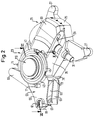
- a motor bearing part 21 is located between the hood 3 and the base of the food processor 1 and a gear bearing part 23 made of plastic (Fig. 2).
- the engine mounting part 21 has in its bottom area a base plate 25, the mechanical stability is increased in particular by stiffening ribs formed on the underside thereof. From the base plate 25 extends two first kitchen machine legs 27, at the Bottom attached in a manner known per se feet of the kitchen machine 1 are (not shown) that protrude through openings in the bottom.
- On the engine mounting part 21 is an electric motor 29 in a correspondingly designed receiving area inserted substantially horizontally, whereby the motor shaft 31 is substantially extends horizontally away from the motor mounting part 21.
- the electric motor 29 is additional by a hood 33 fastened to the motor bearing part 21 or its base plate 25 supported.
- Fig. 2 To simplify the illustration in Fig. 2 are the electronics of the electric motor 29 and other components of the food processor known per se not shown.
- the motor bearing part 21 Laterally next to the electric motor 29 is the motor bearing part 21 as a claw-shaped bearing shell 35 formed with a circular cylindrical section-shaped inner wall 36, the serves as a contact surface and extends essentially over the entire height of the gearbox bearing part 21 extends.
- the inner wall 36 extends perpendicularly thereto Circular section of approximately 210 ° (Fig. 2, Fig. 3).
- a lower edge portion 37 of the claw-shaped Bearing shell 35 has the entire circumferential area of approximately 210 ° a first groove 39 (Fig. 3).
- a transmission bearing cylinder 41 of the transmission bearing part 23 is in the bearing shell 35 from above stuck.
- Inner wall 36 slides a correspondingly formed cylindrical jacket surface Outer wall 43 of the gearbox bearing cylinder 41 along the inner wall 36 of the bearing shell 35.
- formed on the inner wall 36 longitudinal ribs (not shown). The end position has been reached if the lower edge of the gearbox bearing cylinder 41 in the first groove 39 Bearing shell 35 is inserted and the upper edge of the bearing shell 35 in one at the upper edge portion 45 of the gearbox bearing cylinder 41 correspondingly designed second groove 47 stuck (Fig. 3).
- a cover plate 123 (FIG. 7) explained below to the gearbox bearing part 23 and the gearbox bearing cylinder 41 are on these screw eyes and sleeves 71 formed.
- a belt tensioner wall 75 is formed (Fig. 2, Fig. 5).
- a belt tensioner 77 shown in detail between the motor bearing part 21 and the Gearbox bearing part 23 clamped.
- the belt tensioner 77 has an essentially cylindrical main body 79, at the lower end portion of which is perpendicular to the axis of the main body 79 protruding, crescent-shaped actuating arm 81 extends (Fig. 4a, 4b).
- the Tooth 83 is formed on the narrow outer wall of the actuating arm 81, the one for tensioning the belt, as described below, with one on the bottom of the gear bearing part 23 formed locking tooth 85 (Fig. 7) cooperates. Extends over substantially the entire height of the belt tensioner 77 Clamping cams 87.
- An upper projection 89 and a lower projection 91 each overlap the lower edge portion 37 of the bearing shell 35 of the motor bearing part 21 and the Top of the main arm 55 of the gear bearing part 23 and thereby limit the vertical Distance between both.
- the belt tensioner 77 is thereby on the gearbox bearing part 23 or the motor bearing part 21 is held in the corresponding receiving area.
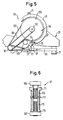
- Fig. 5 is shown in sections and greatly simplified, like a half-crossed intermediate shaft belt 95 between a in the upper and lower bearing shell 61, 63 of Gear ring arm 53 held intermediate shaft 97 (Fig. 6) is tensioned. 5 is the running direction of the intermediate shaft belt 95 is shown by two arrows. On the intermediate wave 97 also run a mixer belt 99 and an additional belt 101, the corresponding Toothed belt wheels 157, 165 of the gear unit 119 are connected (Fig. 5, Fig. 7).
- the additional belt 101 is additionally by a in the transmission bearing part 23 held tensioning roller 103 tensioned.
- the intermediate shaft 97 has one in the upper bearing shell 61 of the gearbox bearing part 23 mounted upper ball bearing 105 and one in the lower bearing shell 63 supported lower ball bearing 107. With the actual wave the intermediate shaft 97 is a first intermediate pinion 109 with an upper first collar 111 non-rotatably connected. Below that there is a second one on the actual shaft Intermediate pinion 113 connected to a lower second collar 115. The two pinions and their running areas are separated from each other by a flanged disc 117 pressed onto the shaft Cut.
- the assembly of the engine and the transmission bearing part 21, 23 or the tensioning of the Belt 95, 99, 101 is simplified as follows: the motor bearing part 21 and the gearbox bearing part 23 are inserted into one another as described above. Because of the claw-shaped Formation of the bearing shell 35 and the design of the gearbox bearing cylinder 41 the two bearing parts 21, 23 are already relatively stable with one another by being inserted into one another connected (Fig. 2, 3, 5). They are supported over a large area to each other and overlap each other. The bearing parts 21, 23 can, however still be rotated relative to each other. Between the pinion of the motor shaft 31 and the The first intermediate pinion 109 of the intermediate shaft 97 runs the intermediate shaft belt 95 half crossed.
- the intermediate shaft 97 when tensioning the intermediate shaft belt 95 in a circle the common central axis of the inner wall 36 of the bearing shell 35 or the outer wall 43 of the gearbox bearing cylinder 41 rotates and in this axis also the first and second toothed belt wheel 157, 165 are rotatably supported, the distance between changes this and the intermediate shaft 97 not.
- Tensioning the additional belt 101 with the help the tensioner roller 103 can therefore be independent of the tensioning of the intermediate shaft belt 95 take place.
- the length of the mixer belt 99 is such that its Tensioning with additional aids is not necessary.
- the intermediate shaft belt runs here 95 about half the height of the adjacent inner wall 36 and outer wall 43 (Fig. 7).
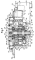
- the completely pre-assembled transmission unit is in the transmission bearing cylinder 41 from above 119 used (Fig. 7).
- the transmission unit has outer ribs 121, as follows is described, which cooperate with the bearing ribs 49 of the gearbox bearing cylinder 41 and a rotationally fixed seat of the gear unit 119 in the gear bearing part 23 to ensure.
- the outer ribs 121 of the gear unit 119 rest on theirs lower end portions each on the shoulder 51 of the gearbox bearing part 23, whereby the gear unit 119 is supported axially downwards.
- the gear unit is at the top 119 secured by a round cover plate 123 made of plastic.
- Plate heel 125 which has a circular center in its bowl-shaped top wall Has output opening 127.
- a suitably trained apron of the work bowl is supported on the circumference 11 onwards.
- the work bowl 11 is still known, not shown
- Fastening means formed that with those formed on the side wall 129
- a flat plate edge 133 extends in a ring shape, on the with the help of an annular seal that is also in this area circular cut hood 3 rests continuously and without gaps.
- the cover plate 123 extends from the top wall of the plate shoulder 125 annular plate apron 135.
- This is the cover plate 123 is rotatably connected to the gearbox bearing part 23 and can by the bowl 11 forces introduced into the cover plate 123 into the gearbox bearing part 23 forward.
- On the inner peripheral wall of the apron 135 are peripheral down from the underside of the top wall of the plate heel 125 extending gear stops 139 provided for the axial securing.
- cover plate 123 In addition three plate screw sleeves 141 are formed on the underside of the cover plate 123, through which, together with the screw eyes or sleeves 71, the cover plate 123 additionally can be fastened to the gearbox bearing part 23. Between the edge of the Output opening 127 and the gear unit 119 is an annular cover plate seal 143 inserted.
- the gear unit 119 has an outer ring gear 151, which in its upper region the outer ribs 121 on the circumference for the rotationally fixed mounting of the gear unit 119 in has the bearing ribs 49 of the gearbox bearing cylinder 41.
- the ring gear is supported 151 with the outer ribs 121 also on the shoulder 51 of the gearbox bearing cylinder 41 from.
- the ring gear 151 has a first and a second internal toothing 153, 154 on, as explained below, roll gears of a planetary gear.
- An output shaft 155 is rotatably mounted in the middle of the gear unit 119. At the bottom The end section of the output shaft 155 is the first toothed belt wheel 157 in a rotationally fixed manner thereon (Fig.
- the output shaft 155 is by means of two deep groove ball bearings 163 rotatably mounted in the gear unit 119, as follows is explained.
- the upper ball bearing 163 is provided with a sealing washer.
- a second gear unit 119 is concentric with the first toothed belt wheel 157 Toothed belt wheel 165 rotatably mounted. This indicates ventilation of the gear unit 119 circumferentially distributed, upwardly extending cooling fins 167.
- the second Timing wheel 165 is supported by an inner bearing shell 169 and an outer bearing shell 171 of the ring gear 151 by an open angular contact ball bearing arranged between them on the ring gear 151.
- the angular contact ball bearing points in a manner known per se an inner bearing ring 173, an outer bearing ring 175 and one in between Ball holder 177 with the corresponding bearing balls.
- the sun gear 179 On the second toothed belt wheel 165 is a sleeve-shaped sun gear 179 rotatably and axially to one in a groove of the sun gear 179 pressed tooth ring 181 secured.
- the sun gear 179 At her top End section is the sun gear 179 on its inner peripheral side with a second, extending up to next to the first coupling bush 161, Coupling socket 185 connected with internal teeth.
- the sun gear 179 and the second coupling bush 185 are supported by two further open angular contact ball bearings 187 in the gear unit 119 to the outside.
- a sealing ring 189 is placed around the second coupling bush 185 in the bearing elements.
- first internal toothing 153 of the ring gear 151 run four first planet gears 191, which are driven by the sun gear 179.
- the planet gears 191 each rotate around first needle rollers 195, which are in an annular lower region of a first planet carrier 197 and in a booster ring firmly connected to it 193 are non-rotatably pressed.
- the first planet carrier 197 is sleeve-shaped third coupling bush 201 firmly connected, the teeth of which radially outwards protrudes.
- To seal the gear unit 119 is also on the third coupling bush 201 a sealing ring 203 is inserted.
- the third coupling bush 201 is supported by a open angular contact ball bearing 205 on a fourth coupling bush 211 and ultimately on the Ring gear 151 of the gear unit 119, as explained below.
- the first planet carrier 197 has external teeth 206 on the circumference, on which roll three second planet gears 207. These rotate, of which as a sun gear serving first planet carrier 197 driven to second needle rollers 209, the are inserted from below into a second planet carrier 211. Its upper end section is designed as a fourth coupling bush 211.
- the second planet carrier 211 is supported by balls 213 on the upper end portion of the ring gear 151.
- the gear unit 119 consists of the metallic output shaft 155, which has no direct Gear meshing in a two-stage planetary gear set assembled without play Plastic is stored (Fig. 7). Between the plastic gear and the output shaft 155 an axial play 215 is provided to the different coefficients of linear expansion of metal and plastic in the gear unit 119 to balance can.
- the output shaft 155 rotates essentially with the without translation Speed of the motor shaft 31 as well as the intermediate shaft 97. At an engine speed under load, the speed of the output shaft 155 is then about 8000 to 12000 revolutions per minute.
- the transmission ratio of the second output or the second Coupling bushing 185 is approximately 5: 1.
- the other gear ratios are in each case in relation to the respective input stage for the third clutch bushing 201 about 3.8: 1 and for the fourth coupling bush 211 about 3.1: 1. This results in the Four output speeds of around 12,000, 2,400, 630 and 200 revolutions per minute.
- the engine speed can also be adjusted in stages. This means that in the area of Four drives or coupling bushes all common work containers in one place the food processor can be switched off and all for normal use of the food processor usual operations without additional gear of the work tools feasible.
- the planetary gear of the gear unit 119 is constructed in two stages. To the inexpensive To be able to use open angular contact ball bearings 187 and 205 is the gear unit 119 from above through the second coupling bush 185 and from below through the Bound sun gear 179, both of which are connected to each other without play. The further Open angular contact ball bearings 173, 175, 177 is then from below using the toothed ring 181 held in the gear unit 119 without play.
Landscapes
- Engineering & Computer Science (AREA)
- Mechanical Engineering (AREA)
- Food Science & Technology (AREA)
- Food-Manufacturing Devices (AREA)
- Transmission Devices (AREA)
Abstract
Description
- Fig. 1
- in einer perspektivischen Ansicht eine Küchenmaschine mit einer darauf abgestellten Arbeitsschüssel.
- Fig. 2
- stark vereinfacht in einer perspektivischen Darstellung das Motorlagerteil und das Getriebelagerteil der Küchenmaschine.
- Fig. 3
- eine schematisierte Schnittdarstellung im wesentlichen entlang der Linie III-III in Fig. 2 im Bereich der Anlageflächen des Motor- und des Getriebelagerteils.
- Fig. 4a und b
- einen Riemenspanner der Antriebseinheit in zwei unterschiedlichen Ansichten in vergrößertem Maßstab.
- Fig. 5
- stark vereinfacht ausschnittweise den Motorlagerteil und den Getriebelagerteil gemäß Fig. 2 in einer Draufsicht.
- Fig. 6
- in einer Seitenansicht in vergrößertem Maßstab eine im Getriebelagerteil gehalterte Zwischenwelle und
- Fig. 7
- abschnittsweise den Getriebelagerteil und eine darin eingesetzte Getriebeeinheit im wesentlichen entlang der Linie VII-VII in Fig. 2.
Claims (12)
- Elektrische Küchenmaschine mit einem Gehäuse, in dem ein Elektromotor mit einer Motorwelle angeordnet ist, die über ein Getriebe zumindest drei konzentrische Abtriebe mit unterschiedlicher Drehzahl antreibt, deren gemeinsame Drehachse räumlich von der Motorwelle beabstandet ist, und an welche Abtriebe in einem auf dem Gehäuse abstellbaren Arbeitsbehältnis umlaufende Arbeitswerkzeuge kuppelbar sind, dadurch gekennzeichnet, daß der schnellste, erste Abtrieb (155) mit einer für ein Mixerwerkzeug geeigneten Drehzahl dreht, und daß das Getriebe zumindest zwei unabhängig voneinander drehbar gelagerte Getriebeeingangsverzahnungen (157, 165) aufweist, so daß der erste Abtrieb (155) außer direktem Eingriff mit den langsameren zweiten und dritten Abtrieben (185, 201) antreibbar ist.
- Elektrische Küchenmaschine nach Anspruch 1, dadurch gekennzeichnet, daß das Getriebe ein Planetengetriebe aufweist, das den zweiten Abtrieb (185) und dritten Abtrieb (201) verbindet.
- Elektrische Küchenmaschine nach Anspruch 2, dadurch gekennzeichnet, daß das Planetengetriebe mehrstufig ausgebildet ist.
- Elektrische Küchenmaschine nach Anspruch 2 oder 3, dadurch gekennzeichnet, daß der zweite Abtrieb ein Sonnenrad (179, 185) des Planetengetriebes bildet.
- Elektrische Küchenmaschine nach Anspruch 2, 3 oder 4, dadurch gekennzeichnet, daß die Welle (155) des ersten Abtriebes im Inneren einer als Hohlwelle ausgebildeten Welle des zweiten Abtriebes (179, 185) gelagert ist.
- Elektrische Küchenmaschine nach einem der vorhergehenden Ansprüche, dadurch gekennzeichnet, daß der erste Abtrieb (155) mittels mindestens eines ersten Riemens (95, 99) mit der Motorwelle (31) verbunden ist.
- Elektrische Küchenmaschine nach einem der vorhergehenden Ansprüche , dadurch gekennzeichnet, daß der zweite Abtrieb (185) mittels mindestens eines zweiten Riemens (95, 101) mit der Motorwelle (31) verbunden ist.
- Elektrische Küchenmaschine nach einem der vorhergehenden Ansprüche , dadurch gekennzeichnet, daß die Drehzahlen der konzentrischen Abtriebe (155, 185, 201, 211) von innen nach außen abnimmt.
- Elektrische Küchenmaschine nach einem der vorhergehenden Ansprüche , dadurch gekennzeichnet, daß die konzentrischen Abtriebe (155, 185, 201, 211) mit Drehzahlen zwischen etwa 200 bis 12000 Umdrehungen pro Minute drehen.
- Elektrische Küchenmaschine nach einem der vorhergehenden Ansprüche , dadurch gekennzeichnet, daß die konzentrischen Abtriebe (155, 185, 201, 211) den gleichen Drehsinn aufweisen.
- Elektrische Küchenmaschine nach einem der vorhergehenden Ansprüche , dadurch gekennzeichnet, daß der erste Abtrieb (155) im wesentlichen mit der Drehzahl der Motorwelle (31) dreht.
- Elektrische Küchenmaschine nach einem der vorhergehenden Ansprüche , dadurch gekennzeichnet, daß die Küchenmaschine vier konzentrische Abtriebe (155, 185, 201, 211) aufweist.
Priority Applications (1)
| Application Number | Priority Date | Filing Date | Title |
|---|---|---|---|
| SI9830016T SI0880931T1 (en) | 1997-05-26 | 1998-05-18 | Electric kitchen appliance |
Applications Claiming Priority (2)
| Application Number | Priority Date | Filing Date | Title |
|---|---|---|---|
| DE19721978A DE19721978C2 (de) | 1997-05-26 | 1997-05-26 | Elektrische Küchenmaschine |
| DE19721978 | 1997-05-26 |
Publications (2)
| Publication Number | Publication Date |
|---|---|
| EP0880931A1 true EP0880931A1 (de) | 1998-12-02 |
| EP0880931B1 EP0880931B1 (de) | 2000-11-15 |
Family
ID=7830527
Family Applications (1)
| Application Number | Title | Priority Date | Filing Date |
|---|---|---|---|
| EP98109025A Expired - Lifetime EP0880931B1 (de) | 1997-05-26 | 1998-05-18 | Elektrische Küchenmaschine |
Country Status (4)
| Country | Link |
|---|---|
| US (1) | US6164812A (de) |
| EP (1) | EP0880931B1 (de) |
| DE (2) | DE19721978C2 (de) |
| SI (1) | SI0880931T1 (de) |
Cited By (3)
| Publication number | Priority date | Publication date | Assignee | Title |
|---|---|---|---|---|
| WO2010133432A1 (de) * | 2009-05-19 | 2010-11-25 | BSH Bosch und Siemens Hausgeräte GmbH | Küchengerät mit einem planetengetriebe |
| EP2457479A1 (de) * | 2010-11-24 | 2012-05-30 | Huiyang Allan Plastics & Electric Industries Co., Limited | Mehrfachantriebssystem für Universal-Küchenmaschine und Mixer |
| WO2013156460A3 (de) * | 2012-04-16 | 2014-01-30 | BSH Bosch und Siemens Hausgeräte GmbH | Dreistufiges planetengetriebe |
Families Citing this family (12)
| Publication number | Priority date | Publication date | Assignee | Title |
|---|---|---|---|---|
| DE102007005110B4 (de) * | 2007-02-01 | 2009-07-02 | BSH Bosch und Siemens Hausgeräte GmbH | Küchenmaschine mit Zwischenzahnrad |
| DE102007011517A1 (de) * | 2007-03-09 | 2008-09-11 | Braun Gmbh | Küchengerät für den häuslichen Bedarf |
| CN101731960B (zh) * | 2008-11-10 | 2013-11-06 | 捷和电机集团有限公司 | 具有至少三个同轴驱动输出的电动食品加工器 |
| CN102106699A (zh) * | 2011-01-21 | 2011-06-29 | 广东新宝电器股份有限公司 | 一种多功能食物处理机 |
| USD655981S1 (en) | 2011-08-05 | 2012-03-20 | Euro-Pro Operating Llc | Blender base interface |
| CN104955368B (zh) * | 2011-12-12 | 2018-05-15 | 尚科宁家运营有限公司 | 多功能食品加工系统 |
| US9149156B2 (en) | 2012-04-09 | 2015-10-06 | Sharkninja Operating Llc | Food processor |
| US20130264405A1 (en) | 2012-04-09 | 2013-10-10 | David M. Audette | Food processor |
| US20170354940A1 (en) * | 2016-06-10 | 2017-12-14 | Vita-Mix Management Corporation | Gear drive container |
| WO2018102367A1 (en) * | 2016-11-29 | 2018-06-07 | Sharkninja Operating Llc | Direction controlled gearbox for appliance |
| FR3089105B1 (fr) * | 2018-12-04 | 2020-12-11 | Seb Sa | Dispositif d’entrainement a corde a commande manuelle |
| US12514403B2 (en) | 2022-03-30 | 2026-01-06 | Whirlpool Corporation | Countertop appliance |
Citations (5)
| Publication number | Priority date | Publication date | Assignee | Title |
|---|---|---|---|---|
| US3109949A (en) * | 1960-06-14 | 1963-11-05 | Licentia Gmbh | Drive unit for household and kitchen attachments |
| DE1186588B (de) * | 1959-11-28 | 1965-02-04 | Oatley Technical Developments | Getriebe fuer Kuechenmaschinen |
| DE2928787B1 (de) * | 1979-07-17 | 1980-05-08 | Zysset & Co Ag K | Kuechenmaschinen-Antriebseinheit |
| EP0570685A1 (de) * | 1992-05-14 | 1993-11-24 | Braun Aktiengesellschaft | Küchenmaschine |
| GB2303537A (en) * | 1995-07-28 | 1997-02-26 | Kenwood Marks Ltd | Apparatus for food preparation |
Family Cites Families (14)
| Publication number | Priority date | Publication date | Assignee | Title |
|---|---|---|---|---|
| DE38899C (de) * | R. MANSFIELD und A. GOD-DARD in Nottingham, England | Neuerung an Spannrahmen für Stickmaschinen | ||
| US2137778A (en) * | 1937-06-25 | 1938-11-22 | Goodman Mfg Co | Planetary geared reduction device |
| US2390742A (en) * | 1939-11-03 | 1945-12-11 | A F Dormeyer Mfg Co | Food mixer |
| US2807447A (en) * | 1954-11-09 | 1957-09-24 | Dormeyer Corp | Food mixer |
| DE1529264C3 (de) * | 1965-08-07 | 1974-01-03 | Siemens-Electrogeraete Gmbh, 1000 Berlin U. 8000 Muenchen | Küchenmaschine |
| US3951351A (en) * | 1974-06-13 | 1976-04-20 | Oster Corporation | Multi-purpose kitchen appliance |
| SE388468C (sv) * | 1975-06-04 | 1978-10-23 | Skf Nova Ab | Planetvexel med alternerande friktions- och kuggkraftoverforing |
| US4141259A (en) * | 1977-02-25 | 1979-02-27 | Nasa | Sequencing device utilizing planetary gear set |
| US4193325A (en) * | 1977-11-09 | 1980-03-18 | Cotreau Alexander P | Gear box |
| US4260272A (en) * | 1979-10-18 | 1981-04-07 | Irene E. M. Lebecque | Processor and dispenser |
| US4380398A (en) * | 1980-09-16 | 1983-04-19 | Burgess Basil A | Dispersion mixer |
| DE3520040A1 (de) * | 1985-06-04 | 1986-12-04 | Herfeld, Friedrich Walter, Dr., 5982 Neuenrade | Vorrichtung zum mischen von gut |
| US4697929A (en) * | 1986-10-28 | 1987-10-06 | Charles Ross & Son Company | Planetary mixers |
| GB8810046D0 (en) * | 1988-04-28 | 1988-06-02 | Swan Housewares Ltd | Multi-purpose kitchen machine |
-
1997
- 1997-05-26 DE DE19721978A patent/DE19721978C2/de not_active Expired - Lifetime
-
1998
- 1998-05-18 EP EP98109025A patent/EP0880931B1/de not_active Expired - Lifetime
- 1998-05-18 DE DE59800335T patent/DE59800335D1/de not_active Expired - Lifetime
- 1998-05-18 SI SI9830016T patent/SI0880931T1/xx unknown
- 1998-05-26 US US09/084,716 patent/US6164812A/en not_active Expired - Lifetime
Patent Citations (6)
| Publication number | Priority date | Publication date | Assignee | Title |
|---|---|---|---|---|
| DE1186588B (de) * | 1959-11-28 | 1965-02-04 | Oatley Technical Developments | Getriebe fuer Kuechenmaschinen |
| US3109949A (en) * | 1960-06-14 | 1963-11-05 | Licentia Gmbh | Drive unit for household and kitchen attachments |
| DE2928787B1 (de) * | 1979-07-17 | 1980-05-08 | Zysset & Co Ag K | Kuechenmaschinen-Antriebseinheit |
| EP0022465A1 (de) | 1979-07-17 | 1981-01-21 | Zyliss Zysset AG | Küchenmaschinen-Antriebseinheit |
| EP0570685A1 (de) * | 1992-05-14 | 1993-11-24 | Braun Aktiengesellschaft | Küchenmaschine |
| GB2303537A (en) * | 1995-07-28 | 1997-02-26 | Kenwood Marks Ltd | Apparatus for food preparation |
Cited By (7)
| Publication number | Priority date | Publication date | Assignee | Title |
|---|---|---|---|---|
| WO2010133432A1 (de) * | 2009-05-19 | 2010-11-25 | BSH Bosch und Siemens Hausgeräte GmbH | Küchengerät mit einem planetengetriebe |
| RU2513380C2 (ru) * | 2009-05-19 | 2014-04-20 | Бсх Бош Унд Сименс Хаусгерете Гмбх | Кухонный прибор с планетарной передачей |
| EP2457479A1 (de) * | 2010-11-24 | 2012-05-30 | Huiyang Allan Plastics & Electric Industries Co., Limited | Mehrfachantriebssystem für Universal-Küchenmaschine und Mixer |
| WO2013156460A3 (de) * | 2012-04-16 | 2014-01-30 | BSH Bosch und Siemens Hausgeräte GmbH | Dreistufiges planetengetriebe |
| CN104379038A (zh) * | 2012-04-16 | 2015-02-25 | Bsh博世和西门子家用电器有限公司 | 三级行星传动机构 |
| CN104379038B (zh) * | 2012-04-16 | 2017-03-08 | Bsh家用电器有限公司 | 三级行星传动机构 |
| RU2615972C2 (ru) * | 2012-04-16 | 2017-04-11 | Бсх Хаусгерете Гмбх | Трехступенчатый планетарный механизм |
Also Published As
| Publication number | Publication date |
|---|---|
| DE59800335D1 (de) | 2000-12-21 |
| US6164812A (en) | 2000-12-26 |
| DE19721978C2 (de) | 2003-03-13 |
| SI0880931T1 (en) | 2001-02-28 |
| DE19721978A1 (de) | 1998-12-03 |
| EP0880931B1 (de) | 2000-11-15 |
Similar Documents
| Publication | Publication Date | Title |
|---|---|---|
| EP0880931B1 (de) | Elektrische Küchenmaschine | |
| DE4421428C1 (de) | Mit einem Elektromotor zu einer Baueinheit verbindbares Planetengetriebe | |
| DE19536177C2 (de) | Planetenreduziergetriebe | |
| DE3804352C2 (de) | ||
| DE69008901T2 (de) | Getriebevorrichtung. | |
| EP1212825B8 (de) | Antrieb für verstellvorrichtungen in kraftfahrzeugen | |
| DE20023013U1 (de) | Vorschaltgetriebe an Motoren mit hoher Drehzahl für Hilfsantriebseinheiten | |
| DE19853459B4 (de) | Planetengetriebe | |
| DE19522981A1 (de) | Saugreinigungsgerät mit einer Saugdüse | |
| EP0292664B1 (de) | Arbeitswerkzeug zum Zubereiten von Nahrungsmitteln | |
| DE19734536A1 (de) | Taumel- oder Exzentergetriebe für eine Fahrzeugsitz-Verstelleinrichtung | |
| DE102016205748B3 (de) | Stellgetriebe | |
| EP0880930B1 (de) | Elektrische Küchenmaschine mit Riemenantrieb | |
| DE102004039057B3 (de) | Untersetzungsgetriebe und dieses verwendende Antriebseinheit | |
| DE10333951B3 (de) | Mehrstufiges Getriebe mit Wellgetriebe | |
| EP0570758B1 (de) | Rühr- und Knetwerkzeug für eine Küchenmaschine, insbesondere Mehrzweckküchenmaschine | |
| DE102024115954B3 (de) | Werkzeugantriebseinheit für ein Schneidmesser eines handgehaltenen Arbeitsgeräts, sowie handgehaltenes Arbeitsgerät mit der Werkzeugantriebseinheit | |
| DE4006434A1 (de) | Mischer | |
| DE69727469T2 (de) | Stufenloses getriebe für fahrzeuge und rasenmäher mit einem solchen getriebe | |
| DE29724640U1 (de) | Elektrische Küchenmaschine | |
| EP0866238B1 (de) | Reduktionsgetriebe | |
| DE3045088A1 (de) | Getriebe fuer eine haushaltskuechenmaschine | |
| DE10008175A1 (de) | Vorschaltgetriebe an Motoren mit hoher Drehzahl für Hilfsantriebseinheiten | |
| EP3503780A1 (de) | Halterungs- und antriebsvorrichtung für werkzeuge in einer küchenmaschine | |
| DE19721972C2 (de) | Antriebseinheit für eine motorische Küchenmaschine |
Legal Events
| Date | Code | Title | Description |
|---|---|---|---|
| PUAI | Public reference made under article 153(3) epc to a published international application that has entered the european phase |
Free format text: ORIGINAL CODE: 0009012 |
|
| AK | Designated contracting states |
Kind code of ref document: A1 Designated state(s): DE FR GB SE |
|
| AX | Request for extension of the european patent |
Free format text: AL;LT;LV;MK;RO;SI PAYMENT 980605 |
|
| 17P | Request for examination filed |
Effective date: 19990602 |
|
| AKX | Designation fees paid |
Free format text: DE FR GB SE |
|
| AXX | Extension fees paid |
Free format text: SI PAYMENT 19980605 |
|
| 17Q | First examination report despatched |
Effective date: 19990701 |
|
| GRAG | Despatch of communication of intention to grant |
Free format text: ORIGINAL CODE: EPIDOS AGRA |
|
| 17Q | First examination report despatched |
Effective date: 19990701 |
|
| GRAG | Despatch of communication of intention to grant |
Free format text: ORIGINAL CODE: EPIDOS AGRA |
|
| GRAH | Despatch of communication of intention to grant a patent |
Free format text: ORIGINAL CODE: EPIDOS IGRA |
|
| GRAH | Despatch of communication of intention to grant a patent |
Free format text: ORIGINAL CODE: EPIDOS IGRA |
|
| GRAA | (expected) grant |
Free format text: ORIGINAL CODE: 0009210 |
|
| AK | Designated contracting states |
Kind code of ref document: B1 Designated state(s): DE FR GB SE |
|
| AX | Request for extension of the european patent |
Free format text: SI PAYMENT 19980605 |
|
| GBT | Gb: translation of ep patent filed (gb section 77(6)(a)/1977) |
Effective date: 20001115 |
|
| REF | Corresponds to: |
Ref document number: 59800335 Country of ref document: DE Date of ref document: 20001221 |
|
| ET | Fr: translation filed | ||
| PLBE | No opposition filed within time limit |
Free format text: ORIGINAL CODE: 0009261 |
|
| STAA | Information on the status of an ep patent application or granted ep patent |
Free format text: STATUS: NO OPPOSITION FILED WITHIN TIME LIMIT |
|
| 26N | No opposition filed | ||
| REG | Reference to a national code |
Ref country code: GB Ref legal event code: IF02 |
|
| REG | Reference to a national code |
Ref country code: SI Ref legal event code: IF |
|
| REG | Reference to a national code |
Ref country code: SI Ref legal event code: KO00 Effective date: 20140225 |
|
| REG | Reference to a national code |
Ref country code: DE Ref legal event code: R081 Ref document number: 59800335 Country of ref document: DE Owner name: BSH HAUSGERAETE GMBH, DE Free format text: FORMER OWNER: BSH BOSCH UND SIEMENS HAUSGERAETE GMBH, 81739 MUENCHEN, DE Effective date: 20150402 |
|
| REG | Reference to a national code |
Ref country code: FR Ref legal event code: PLFP Year of fee payment: 18 |
|
| REG | Reference to a national code |
Ref country code: FR Ref legal event code: CD Owner name: BSH HAUSGERATE GMBH Effective date: 20151022 |
|
| REG | Reference to a national code |
Ref country code: FR Ref legal event code: PLFP Year of fee payment: 19 |
|
| REG | Reference to a national code |
Ref country code: FR Ref legal event code: PLFP Year of fee payment: 20 |
|
| PGFP | Annual fee paid to national office [announced via postgrant information from national office to epo] |
Ref country code: DE Payment date: 20170531 Year of fee payment: 20 Ref country code: FR Payment date: 20170522 Year of fee payment: 20 Ref country code: GB Payment date: 20170524 Year of fee payment: 20 |
|
| PGFP | Annual fee paid to national office [announced via postgrant information from national office to epo] |
Ref country code: SE Payment date: 20170523 Year of fee payment: 20 |
|
| REG | Reference to a national code |
Ref country code: DE Ref legal event code: R071 Ref document number: 59800335 Country of ref document: DE |
|
| REG | Reference to a national code |
Ref country code: GB Ref legal event code: PE20 Expiry date: 20180517 |
|
| REG | Reference to a national code |
Ref country code: SE Ref legal event code: EUG |
|
| PG25 | Lapsed in a contracting state [announced via postgrant information from national office to epo] |
Ref country code: GB Free format text: LAPSE BECAUSE OF EXPIRATION OF PROTECTION Effective date: 20180517 |