EP0880686B1 - Debitmetre fonctionnant dans des fluides caustiques et comportant un bo tier etanche - Google Patents
Debitmetre fonctionnant dans des fluides caustiques et comportant un bo tier etanche Download PDFInfo
- Publication number
- EP0880686B1 EP0880686B1 EP97904828A EP97904828A EP0880686B1 EP 0880686 B1 EP0880686 B1 EP 0880686B1 EP 97904828 A EP97904828 A EP 97904828A EP 97904828 A EP97904828 A EP 97904828A EP 0880686 B1 EP0880686 B1 EP 0880686B1
- Authority
- EP
- European Patent Office
- Prior art keywords
- housing
- fluid flow
- flow meter
- recited
- pressure
- Prior art date
- Legal status (The legal status is an assumption and is not a legal conclusion. Google has not performed a legal analysis and makes no representation as to the accuracy of the status listed.)
- Expired - Lifetime
Links
Images


Classifications
-
- G—PHYSICS
- G01—MEASURING; TESTING
- G01L—MEASURING FORCE, STRESS, TORQUE, WORK, MECHANICAL POWER, MECHANICAL EFFICIENCY, OR FLUID PRESSURE
- G01L7/00—Measuring the steady or quasi-steady pressure of a fluid or a fluent solid material by mechanical or fluid pressure-sensitive elements
-
- G—PHYSICS
- G01—MEASURING; TESTING
- G01F—MEASURING VOLUME, VOLUME FLOW, MASS FLOW OR LIQUID LEVEL; METERING BY VOLUME
- G01F1/00—Measuring the volume flow or mass flow of fluid or fluent solid material wherein the fluid passes through a meter in a continuous flow
- G01F1/05—Measuring the volume flow or mass flow of fluid or fluent solid material wherein the fluid passes through a meter in a continuous flow by using mechanical effects
- G01F1/34—Measuring the volume flow or mass flow of fluid or fluent solid material wherein the fluid passes through a meter in a continuous flow by using mechanical effects by measuring pressure or differential pressure
- G01F1/36—Measuring the volume flow or mass flow of fluid or fluent solid material wherein the fluid passes through a meter in a continuous flow by using mechanical effects by measuring pressure or differential pressure the pressure or differential pressure being created by the use of flow constriction
- G01F1/40—Details of construction of the flow constriction devices
- G01F1/44—Venturi tubes
-
- G—PHYSICS
- G01—MEASURING; TESTING
- G01F—MEASURING VOLUME, VOLUME FLOW, MASS FLOW OR LIQUID LEVEL; METERING BY VOLUME
- G01F1/00—Measuring the volume flow or mass flow of fluid or fluent solid material wherein the fluid passes through a meter in a continuous flow
- G01F1/05—Measuring the volume flow or mass flow of fluid or fluent solid material wherein the fluid passes through a meter in a continuous flow by using mechanical effects
- G01F1/34—Measuring the volume flow or mass flow of fluid or fluent solid material wherein the fluid passes through a meter in a continuous flow by using mechanical effects by measuring pressure or differential pressure
- G01F1/36—Measuring the volume flow or mass flow of fluid or fluent solid material wherein the fluid passes through a meter in a continuous flow by using mechanical effects by measuring pressure or differential pressure the pressure or differential pressure being created by the use of flow constriction
- G01F1/363—Measuring the volume flow or mass flow of fluid or fluent solid material wherein the fluid passes through a meter in a continuous flow by using mechanical effects by measuring pressure or differential pressure the pressure or differential pressure being created by the use of flow constriction with electrical or electro-mechanical indication
Definitions
- This invention relates generally to flow meters, and more particularly, to a flow meter which may be connected in-line within a chemically corrosive fluid flow circuit in either a liquid or gaseous state, wherein the flow meter includes two chemically inert pressure sensors that are contained within a non-contaminating body on opposite sides of a constriction and may be isolated from the fluid flow circuit.
- caustic fluids are used in the processing of sensitive materials.
- the susceptibility to contamination is a significant problem faced by manufacturers.
- the manufacturers may, for example, process semiconductor wafers using caustic fluids.
- Various manufacturing systems have been designed to reduce the contamination of the sensitive materials by foreign particles and generated vapors.
- the processing equipment used in the manufacturing systems include designs that attempt to eliminate all sources of damaging contaminants.
- the processing of the sensitive materials often involves the direct contact of the sensitive materials with the caustic fluids. Hence, it is critical that the caustic fluids are delivered to the processing site in an uncontaminated state.
- Various components of the processing equipment are commonly designed to reduce the amount of particulate generated and to isolate the processing chemicals from contaminating influences.
- Liquid transporting systems carry the caustic chemicals from supply tanks through pumping and regulating stations and through the processing equipment itself.
- the liquid chemical transport systems which includes pipes, tubing, monitoring devices, sensing devices, valves, fittings and related devices, are frequently made of plastics resistant to the deteriorating effects of the toxic chemicals.
- Metals which are conventionally used in such monitoring devices, cannot reliably stand up to the corrosive environment for long periods of time. Hence, the monitoring and sensing devices must incorporate substitute materials or remain isolated from the caustic fluids.
- the processing equipment commonly used in semiconductor manufacturing has monitoring and sensing devices, such as pressure sensors and flow meters. These monitoring and sensing devices are connected in a closed loop feedback relationship and are used in monitoring and controlling the equipment. These monitoring and sensing devices must also be designed to eliminate any contamination which might be introduced.
- a turbine flow meter known. in the art has moving parts that wear out and become corrupted when exposed to the caustic fluids. Further, these turbine flow meters tend to trap fluid that contaminate subsequent process fluids. In avoiding the use of turbine flow meters, the monitoring and sensing devices may incorporate sensors. These devices must also be designed to avoid the introduction of particulate, unwanted ions, or vapors into the processing steps.
- pressure sensors in flow meters
- a venturi, nozzle, orifice, or weir meter may be used for measuring or controlling the rate of flow.
- a differential sensor or pitot tube with sensors may be used, however, both these arrangements require small ports or capillaries that can easily plug or trap contaminants.
- the prior art does not disclose a flow meter which may be positioned in-line within a fluid flow circuit carrying corrosive materials, and which does not contaminate the processing fluids.
- An in-line mechanical fluid pressure responsive gauge separated from the fluid flow by a protective membrane is known in the art.
- the gauge is contained within a housing having a cavity filled with a sensor fluid.
- the cavity is formed adjacent the fluid flow and separated by the protective but flexible membrane.
- the sensor fluid contained within the cavity is typically a silicone oil.
- a change in pressure within the fluid affects the silicone oil pressure within the cavity.
- the oil pressure is detected by the mechanical pressure responsive gauge.
- the fluid within the cavity typically has large coefficient of thermal expansion, which may cause a significant deflection in the membrane.
- the large deflection changes in the protective membrane increases the likelihood that the fluid within the cavity will leak into the fluid flow, contaminating the flow circuit.
- the accuracy of the pressure gauge is negatively affected by the large thermal expansions of the sensor fluid.
- the capacitance proximity device in U.S. Patent No. 5,316,035 (the '035 patent) describes the use of a capacitance proximity monitoring device in corrosive atmosphere environments.
- the capacitance proximity device is described as being incorporated into a functional apparatus, such as a piping system including valves and couplings.
- the capacitance proximity device serves as a functional portion of the apparatus and creates a sensing region within a predetermined area. It is then used to determine the change of electrical characteristics within the predetermined area as various fluids flow past the predetermined area.
- the complex valving is used to control fluid flow and the possibility exists that the fluid will leak and contaminate the processing fluid flow.
- None of the above identified prior art discloses or even considers a device capable of determining the fluid flow rate within the caustic chemical transport system of chemical processing equipment. Further, none of the above identified prior art discloses a device that determines either or both the fluid flow rate and the pressure within the fluid flow. Monitoring the fluid flow within the chemical transport system is useful for several reasons. First, a change in flow within the system may be indicative of leakage within the system. Second, the flow within the transport system is regulated to avoid exceeding predetermined safety limits. Third, a change in fluid flow may indicate an obstruction or infiltration of contaminants into the fluid flow circuit.
- US 5,410,916 describes a flow-through pressure sensor adapted to avoid the creation of crevices or creases in a fluid flow path which could harbour bacteria and be difficult to flush or cleanse. It does not teach spaced apart cavities each extending transversely into a longitudinal bore having a constriction disposed between the two spaced apart cavities.
- the purpose of the present invention is to provide a flow meter that may be coupled in-line to a flow circuit transporting corrosive fluids, where the rate of flow may be determined from a differential pressure measurement taken within the flow circuit.
- the flow meter includes two pressure sensors contained within a non-contaminating body, wherein the pressure sensors are separated in the flow circuit by a constricting member.
- the flow meter compensates for changes of temperature within fluid flow circuit and provides a zeroing feature which compensates for differences in pressure between the two sensors when the fluid is at rest.
- the components of the flow meter include a housing, a cover, an electrical connector, pressure fittings, isolation membranes, sealing rings, two pressure sensors, a circuit board and electronic circuitry, spacer rings and hold down rings.
- the flow meter's housing has a bore extending therethrough, which forms a passage or conduit through which fluids flow, when the housing is connected in-line in a fluid flow circuit.
- Aligned and sealably connected to the opposed open ends of the bore are pressure fittings.
- the pressure fittings are constructed from a chemically inert material and are readily available and known to those skilled in the art.
- the housing also has two pressure transducer receiving cavities extending from an external surface thereof, wherein each such cavity communicates independently with the bore.
- the bore tapers to a constricting region located between the two cavities. The restricted region results in a pressure drop within the bore across points adjacent the two cavities. This change pressure may be detected by pressure sensor transducers placed within each of the two cavities. The rate of flow is determined from the change in pressure. The determination of the rate of flow using the two pressure sensors is discussed below.
- a hybrid or fully integrated electronic circuit disposed in the housing is operatively coupled to both pressure sensor transducers and to an electrical connector contained in the cover.
- the electronic circuit develops a signal which is a measure of the rate of flow within the flow circuit from information sensed by both pressure sensors. Further, the electronic circuit may develop a signal corresponding to one or the other of the downstream or upstream static pressures within the fluid flow circuit, such that the orientation of the flow meter within the flow circuit is interchangeable and the direction of flow may be indicated by comparing the sensed pressure from each pressure sensor.
- a correction may be made to the sensed pressures to correct for non-linearities as a result of gas density differences.
- This electronic circuit may also be used in combination with temperature sensitive components to adjust the pressure measurement associated with each cavity based upon temperature changes within the flow circuit. Further, a switch may be incorporated into the electronic circuit that allows zeroing of the flow meter by the user.
- the electronic circuit is coupled by electrical leads to the electrical connector and power may be transmitted to the electronic circuit through the electrical leads mating at the connector with an external power supply. Further, an analog output such as a standard 4-20 milliamps signal proportional to the calculated rate of flow may be transmitted through additional electrical leads.
- the housing comprises two symmetric housing halves. Each housing half includes a longitudinal bore and counter bore for receiving a restriction member therein.
- a portion of the longitudinal bore disposed between the two cavities has a third cavity which receives a removable insert.
- the insert has a channel extending therethrough, thereby forming a passage from one bore section to the other.
- a bushing is friction fit within the bore between the two cavities to thereby create the constriction.
- inert sapphire pressure transducers are positioned within respective cavities and in direct contact with the fluid flow, thereby eliminating the isolation membrane.
- Another object of the present invention is to provide a flow meter, wherein inert pressure sensor components of the flow meter may be situated in direct contact with the fluid flow.
- Yet another object of the present invention is to provide a flow meter having isolation members that are in direct contact with the associated pressure sensors, the isolation members acting to isolate the sensors and associated electronic circuitry from potentially corrosive processing chemicals and precluding introduction of contaminating substances into the processing fluids being transported.
- Still another object of the present invention is to provide a flow meter, wherein a pressure of the flow circuit is measured non-intrusively at two independent points within the flow circuit to thereby determine the rate of flow within the flow circuit.
- a further object of the present invention is to provide a non-contaminating flow meter that compensates for initial pressure differences between the two pressure sensor transducers when the flow rate is zero.
- Yet another object of the present invention is to provide a non-contaminating, chemically inert flow meter that determines either the rate of flow or pressure within the fluid flow circuit.
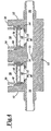
- the flow meter 10 generally includes a housing or body 12, mounting fastener slots 14, pressure inlet/outlet fittings 16 and 18, and a cover 20.
- An electrical connector 22, of known construction, may be removably attached in the cover 20.
- the housing 12 and cover 20 are preferably manufactured from a chemically-inert, non-contaminating polymer such as polytetrafluoroethylene (PTFE).
- PTFE polytetrafluoroethylene
- the cover 20 has bores 24 extending through it for mounting the cover 20 to the housing 12 with appropriate screws (not shown).
- a suitable gasket (not shown) is preferably positioned between the cover and housing to allow the cover 20 to be sealed to the housing 12.
- a gasket or seal manufactured from a multi-layer fabric, sold under the GOR-TEX® trademark by W.L. Gore & Assoc., Inc., allows venting of an internal area of the housing 12 for true atmospheric pressure reference, while restricting the flow of liquids into the internal area of the housing 12.
- a longitudinal bore 26 extends through the housing 12 forming a conduit.
- the bore 26 serves as the fluid flow passage within the fluid flow circuit.
- the orientation of the flow meter 10, within the fluid flow circuit, may be reversed without affecting its effectiveness.
- First and second transversely extending cavities 28 and 30 extend all the way from an outer surface 32 of the housing 12 to the bore 26.
- cavities 28 and 30 may each extend into the housing from a different sidewall of the housing.
- the two cavities 28 and 30 are separated a predetermined distance by dividing wall 34.
- the bore 26 also includes a constriction or restriction 35 located between the two cavities 28 and 30.
- an annular lip 36 is formed. Each lip 36 surrounds and further defines the opening to each cavity 28 and 30 from the bore 26.
- a thin flexible polymer disk or isolation membrane 38 is positioned on the lip 36 of each cavity 28 and 30.
- the membrane is preferably constructed to have a thickness in a range between .001 and .040 inches (25-1000 ⁇ m).
- the upper surface of membrane 38 is abraded so as to create a pattern of grooves or channels.
- the flexible membrane 38 is manufactured from tetrafluoroethylene fluorocarbon polymers.
- tetrafluoroethylene fluorocarbon polymer is sold under the TEFLON® trademark by E.I. duPont Nemours.
- the isolation membranes 38 may have a thin film formed on its surface, to act as a buffer to any caustic chemicals leaking into the pressure transducer cavities.
- the thin film may further act as an electric shield for capacitance sensors, thereby obviating inaccuracy problems resulting from changes in dielectric properties as fluids flow through the flow meter.
- the thin film may for example be a carbon powder and epoxy ink painted onto the isolation membrane 38 or a thin film of carbon may be surface molded into the isolation membrane.
- the coated disk membrane 38 is preferably molded, since spraying or manufacturing by some other process may leave pinhole paths therein.
- the isolation membrane may be reinforced with carbon fibers, thereby increasing the elastic behavior of the isolation membrane 38, and reducing the cold flow tendencies of the PTFE isolation membrane.
- each lip 36 and isolation membrane 38 may be altered as described in the aforementioned co-pending application WO-A-97/13132.
- Each pressure transducer 42 and 44 is held in place within their respective cavities 28 and 30 by spacer ring 48 and externally threaded hold down ring 50.
- the isolation membranes 38 and transducers 42 and 44 are sealed within the housing 12 by chemically inert o-ring seals 52 and 54.
- a redundant seal is created by the positioning of o-rings 52 and 54.
- the seals 52 and 54 are readily available and of known construction to those skilled in the art.
- An additional spacer ring 56 (see Figure 4) may be necessary, depending upon the dimensions of the pressure transducer.
- a drain or conduit 40 may be formed extending through the housing wall 32 into each cavity 28 and 30 between the redundant seals 52 and 54, thereby draining the area between the redundant seals. In this manner, the drain acts as a drainage, passageway or outlet, in the event that fluids leak past seal 52 from the fluid flow circuit.
- a sensor 41 is positioned within the drain 40 and is electrically connected (by leads not shown) to the electric circuit 46. Those skilled in the art will appreciate that a conductive sensor, capacitive sensor or non-electric fiber optic sensor may equally be used to sense the presence of fluids in the drain 40. When fluid leaks past the first seal, the fluid activates the sensor 41, thereby transmitting a signal to the electric circuit 46 which subsequently sets off an alarm.
- the redundant sealing arrangement helps prevent exposure of the pressure transducers 42 and 44 and electric circuit 46 from the damaging affects of the caustic fluids.
- the redundant seal also further isolates the fluid flow, thereby reducing the potential contamination of the fluids.
- a tube (not shown) may be connected to the drain 40, to thereby carry away the caustic fluids to a non-contaminating area.
- each pressure sensor may be of a capacitance type or piezoelectric type known to those skilled in the art.
- the base of each pressure sensor is in direct contact with the membrane 38 and may be either in pressure contact with or bonded to the membrane by an adhesive, thermal welding or by other known means.
- the base may have a carbon film formed thereon, to act as an additional shield against potential leakage and further to act as electric shield.
- an alumina ceramic pressure sensor may be used, wherein the alumina ceramic pressure sensor comprises a thin, generally compliant ceramic sheet having an insulating spacer ring sandwiched between a thicker, non-compliant ceramic sheet.
- the first thin ceramic sheet or diaphragm is approximately .005 to .050 inches (0.13 - 1.27 mm) in thickness with a typical thickness of .020 inches (0.51 mm).
- the thicker ceramic sheet has a thickness range between .100 to .200 inches (2.5 - 5.1 mm).
- the spacer ring may be constructed of a suitable material such as a glass, polymer or alternatively the ceramic sheets may be brazed together.
- the flexible membrane 38 could be eliminated if the pressure sensor used is of the sapphire capacitive pressure transducer type.
- a sapphire transducer is inert, and is resistant to wear when subjected to caustic fluids. Having a sapphire sensor in direct communication with the fluid flow, further enhances the pressure measurements of each transducer.
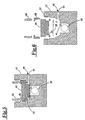
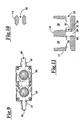
- FIG. 7-9 an alternate embodiment of the flow meter's housing 12 is shown.
- the housing 12 is split into two sections or halves 58 and 60, wherein the downstream section 58 has a cavity 62 and longitudinal bore 66, and upstream section 60 has a cavity 64 and longitudinal bore 68 formed therein.
- the longitudinal bores 66 and 68 of each section 58 and 60 respectively, have respective counter bores 70 and 72.
- the two sections 58 and 60 are aligned and engaged, such that the counter bores 70 and 72 are aligned, thereby forming a hollow cavity in which a restriction member 74 is inserted (see Figures 8 and 9).
- the restriction member 74 has a central opening 76 extending therethrough (see Figure 10), which is aligned with the longitudinal bores 66 and 68.
- the restrictions central opening 76 is smaller in diameter than either section's longitudinal bores 66 and 68.
- the restriction member 74 is sealably engaged with each housing section's bore 66 and 68 by chemically inert sealing o-rings known in the art. Without any limitation intended, the restriction member 74 and associated sealing rings are preferably constructed of polytetrafluoroethylene.
- a third cavity 78 extends from a bottom outer surface of the housing 12 and into communication with the bore 26.
- the third cavity 78 is formed midway between the first and second cavities 28 and 30.
- a replaceable insert or plug 80 is inserted and sealed within the third cavity 78.
- the plug 80 has an opening or channel 82 (not shown) extending therethrough, wherein the channel 82 is aligned with the longitudinal bore 26, thereby forming a passage from one bore section to the other.
- the third cavity 78 may extend from a top outer surface of the housing 12. In this arrangement, once the cover 20 is sealed to the housing 12, external access to the third cavity 78 would be limited.
- the diameter of the channel 82 is less than the diameter of either bore section 26, thereby creating the constriction or restricted region.
- the plug 80 engages with the third cavity 78, by chemically inert o-rings 84 known in the art.
- the plug 74 and sealing rings 84 are constructed of polytetrafluoroethylene, wherein the sealing rings 84 seal the plug 74 within the third cavity 78.
- the plug may alternatively be constructed of sapphire, a material resistant to wear from the fluid flow.
- constriction 35 is formed by a bushing that is friction fit between the cavities 28 and 30.
- the bushing includes a bore of smaller cross-section than longitudinal bore 26, which interconnects the remaining bore sections.
- the constriction 35 may be created by a variety of forms including those discussed above.
- the constriction may be constructed of sapphire, thereby extending the longevity of the flow meter.
- sapphire is an inert substance, highly resistant to wear from caustic flowing fluids.
- each embodiment is dimensioned to universally accept the same pressure fittings 16 and 18, cover 20, isolation membrane 38, pressure sensors 42 and 44, electronic circuit 46, spacer ring 48, and hold down ring 50. Also, each embodiment has a constricting area of varying construction between the sensor receiving cavities to create a pressure drop as the fluid flow traverses the restriction.
- the electronic circuit module 46 is positioned above the ceramic pressure transducers 42 and 44 and is electrically coupled to the conductive surfaces of the ceramic pressure transducers 42 and 44.
- the electronic circuit module 46 is also connected by suitable leads (not shown) to internal contacts of the connector 22 ( Figure 1).
- the electrical connector 22 is made of a chemically inert material and preferably may be of a type available from Pneumatico, part number po3rsd-00004-24.
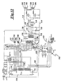
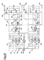
- FIG. 12 there is shown an electrical circuit schematic diagram of the electronic circuit module 46.
- the electronic circuit is used to convert the pressure readings from the two pressure transducers 42 and 44 to a 4-20 mA analog representation of flow or, alternatively, a pressure reading of the downstream pressure transducer 44.
- the raw analog signal from the upstream transducer 42 is supplied to input terminal 102 and, likewise, the raw analog transducer output signal from the downstream transducer 44 is supplied to the input terminal 104.
- Terminals 106 and 108 are power input terminals and terminals 110 and 112 are connected to the ground bus 114 (see Figure 12).
- an analog temperature compensation chip 118 Connected between the +5 volt power bus 116 and the ground bus 114 is an analog temperature compensation chip 118 which may preferably comprise a type LM 45 device available from National Semiconductor, Inc.
- the temperature compensation chip 118 has its v + terminal connected by conductor 120 to the +5v bus 116 and its v - input connected through a semiconductor diode 122 to the ground bus 114.
- the diode 122 provides an offset, so that the signal proportional to temperature produced on output terminal 124 of the temperature compensation chip 118 can go below 0°C, i.e., assuming a negative value.
- the raw sensor signals produced on input terminals 102 and 104, together with the temperature compensation signal produced at terminal 124 are individually applied to a four channel sigma delta type analog to digital (A/D) converter chip 126.
- the chip 126 may preferably comprise an AD7714 integrated circuit chip supplied by Analog Devices Corporation. Those wishing details of the mode of operation of that integrated circuit are referred to the data sheets available from Analog Devices Corporation.
- the sigma delta A/D converter 126 includes a digital filtering capability for the analog pressure inputs where the cut off frequency of the low pass filter is a programmable quantity set by the software executed in the microprocessor chip 128.
- the microprocessor 128 may comprise a type PIC 16C73 integrated circuit available from Microchip Technology Corporation.
- the resistive voltage divider including resistors 130 and 132, which are connected between the positive bus 116 and the ground bus 114, provide voltage compensation when the pressure data is being linearized.
- the A/D chip 126 provides its serial output data stream on line 134 to a data input terminal 136 on the microprocessor 128.
- the serial data from the A/D converter chip 126 is clocked out, under control of timing signals provided by a crystal controlled clock circuit indicated generally by numeral 138.
- This clock circuit 138 also provides timing pulses over line 140 to the clock input terminal 142 of the microprocessor chip 128 for controlling its timing.
- the microprocessor 128 is programmed to compute the instantaneous pressure differences being picked up by the upstream and downstream transducers 42 and 44 and to perform any necessary zeroing adjustments and scaling.
- a switch 143 is connected to the microprocessor 128. When switch 143 is switched to the on position, the difference in pressure between the two sensors 42 and 44 is calculated. This value is then stored. Typically, the user will activate switch 143 to test mode when there is no fluid flow. Any difference in pressure during no fluid flow will be stored in the microprocessor. The user then de-activates the switch 143. During fluid flow, the stored value is subtracted from the difference in pressures, thereby performing the zeroing adjustment. A test is also made to determine whether the thus scaled pressure difference is above or below preestablished high/low limits. If the pressure difference is above or below the pre-established high/low limits, an alarm is activated. When the pressure difference is within the preestablished limits, the rate of flow is computed.
- the microprocessor 128 thus computes the rate of flow from the data received from the two pressure sensors.
- the rate of flow approximates more closely a constant multiplied by P 1 - P 2 .
- a low flow limit could be built into the system, such that if the "Reynolds number" is below a certain threshold, the flow meter identify the flow rate as zero.
- Figure 13 illustrates the circuitry used to convert the rate of flow computed by the microprocessor 128 into an analog signal falling in the range of from 4mA to 20mA for use by existing analog control systems. That is to say, the digital value of flow computed by the microprocessor 128 is converted to an analog signal whose current amplitude is directly proportional to the computed flow value and is in the range between 4mA and 20mA.
- the system may also be used to provide a 4 mA-20 mA current signal proportional to the pressure sensed by the downstream transducer 44 or upstream transducer 42. More particularly, as seen in Figure 13, the circuitry is partitioned into substantially identical upper and lower channels where the 4mA to 20mA current signal proportional to flow becomes available across the output terminals 144 and 146, and the 4mA - 20mA current signal proportional to pressure becomes available across the output terminals 148 and 150.
- the microprocessor 128 provides a clocking signal on line 152 which connects to a corresponding line 152 in Figure 13.
- first and second data output lines 154 and 156, respectively, coming from the microprocessor 128 connect to the corresponding lines 154 and 156 at the left hand side of the schematic Figure 13.
- Signals for determining which of the two channels in Figure 13 is to be operative is also provided by way of a digital to analog converter chip select signal emanating from the microprocessor 128 on line 158.
- This signal is provided to an opto isolator circuit 160 and 162 whose output goes to the "chip select" terminal on either the digital-to-analog (D/A) converter chip 164 or the digital-to-analog chip 166.
- the D/A converters 164 and 166 may comprise a 12 bit device, such as a type MAX538 D/A converter chip available from Maxim Corporation.
- the clock signals on line 152 are also optically isolated via opto couplers 168, 170, 172, and 174 with the resulting signals being applied to the respective D/A converters.
- the circuitry to the right of the vertical-line 176 functions co convert the analog signal output, from either the digital to analog converter 164 or the digital to analog converter 166, to a current signal in the range of from 4mA to 20mA depending upon the amplitude of the voltage output from the D/A converters 164 and 166.
- the output from the D/A converter 164 is coupled through a resistor 178 to the non-inverting input of an operational amplifier 180.
- the inverting input thereof is connected to ground 194.
- the output of the operational amplifier 180 is connected to the gate electrode of a FET device 182 as are bias resistors 184 and 186.
- a voltage reference for the FET device 182 and for the D/A converter 164 is obtained by means of series connected diodes 188 and 190 which are connected in series across the positive voltage bus 192 and the ground bus 194.
- the voltage to current converter circuitry associated with the D/A converter 166 illustrated to the right of the vertical line 176 is substantially identical to what has already been described in association with the D/A converter 164, it is deemed unnecessary to repeat that description.
- the output lines 196 and 198 shown coming from the microprocessor 128 in Figure 12, are applied via corresponding numbered lines in Figure 13 to an opto coupler 200.
- the output from the opto coupler 200 indicates that power is present on lines 144 and 146 and also on lines 148 and 150.
- the microprocessor chip 128 has associated with it a RS232 serial port indicated generally by numeral 202.
- the flow meter device of the present invention is capable of communicating with a variety of peripheral devices including a further central processing unit (not shown).
- the electronic circuit 46 may also adjust the pressure and flow output as the temperature within the flow circuit changes by including a thermistor or like component therein. Each pressure transducer is corrected for temperature independently.
- One means of temperature compensation is disclosed in U.S. patent 4,598,381.
- the user couples the flow meter 10 into a fluid flow circuit through pressure fittings 16 and 18.
- the pressure adjacent each of the two cavities is detected by the electric circuit 46, whereby the rate of flow is calculated from the two detected pressures.
- the gauge pressure or absolute pressure may equally be used. From the determination of 5 the flow rate, an alarm is activated if the flow rate or downstream pressure increases or decreases above or below predetermined limits, or the processing equipment is turned off.
- the flow rate may be calibrated so that minimum desired output values are associated with minimum pressure and maximum desired output pressures are associated with maximum pressure.
- a pressure sensor intended to measure 0 to 100 psig (pounds per square inch gauge) (0 - 689.5 kPa) can be calibrated to read 4mA (milliamps) at 0 psig and 20mA at 100 psig (689.5 kPa).
- the inert Teflon isolation membrane in intimate contact with the pressure sensors, the working fluid does not contact the surfaces of the sensor which could lead to contamination.
- the sealing arrangements disclosed ensures that the working fluid does not enter the cavities of the housing 12 and adversely affect the electronic circuitry 46.
Claims (21)
- Débitmètre chimiquement inerte (10) pour fluide, adapté pour être connecté en ligne à un circuit d'écoulement de fluide, comprenant :(a) un boítier chimiquement inerte (12) ayant un alésage longitudinal (26, 66, 68) d'une première zone en coupe transversale prédéterminée s'étendant à travers ledit boítier formant un conduit d'écoulement de fluide, dans lequel une extrémité d'entrée (16, 18) et une extrémité de sortie (18, 16) du conduit sont adaptées pour la connexion au circuit d'écoulement de fluide, ledit boítier ayant en outre des première et seconde cavités séparées (28, 30 ; 62, 64) chacune s'étendant transversalement à partir d'une surface externe (32) dudit boítier (12) dans l'alésage longitudinal (26) dudit boítier, l'alésage longitudinal ayant un rétrécissement (35, 74, 82) situé entre lesdites première et seconde cavités (28, 30), le rétrécissement ayant un second alésage d'une seconde zone en coupe transversale qui est inférieure à la première zone en coupe transversale prédéterminée ;(b) des premiers moyens (42) de détection d'une première pression dans le circuit d'écoulement de fluide, lesdits premiers moyens de détection étant contenus à l'intérieur de ladite première cavité (28) ;(c) des seconds moyens (44) de détection d'une seconde pression dans le circuit d'écoulement de fluide, lesdits seconds moyens de détection étant contenus dans ladite seconde cavité (30) ;(d) des moyens (48, 56) de maintien des premiers et seconds moyens de détection dans une position fixe à l'intérieur des cavités du boítier ; et(e) un circuit électronique (46) contenu à l'intérieur du boítier et couplé aux premiers et seconds moyens (42, 44) de détection, moyennant quoi le circuit électronique reçoit des signaux proportionnels aux première et seconde pressions détectées à l'intérieur de l'alésage et produit un signal qui est une mesure d'un débit d'écoulement à l'intérieur de l'alésage et/ou d'une pression à l'intérieur de l'alésage.
- Débitmètre selon la revendication 1, dans lequel le circuit électronique (46) produit un signal proportionnel à un débit d'écoulement de fluide à l'intérieur de l'alésage.
- Débitmètre selon la revendication 2, dans lequel le circuit électronique (46) produit ledit signal proportionnel à un débit d'écoulement de fluide à l'intérieur de l'alésage déterminé à partir des première et seconde pressions détectées.
- Débitmètre selon la revendication 1 ou la revendication 3, dans lequel le rétrécissement de l'alésage longitudinal comprend une pièce rapportée amovible (74, 80).
- Débitmètre selon la revendication 3, dans lequel le boítier (12) comprend des premier et second demi-boítiers (58, 60) chacun comprenant un alésage longitudinal (66, 68) et un contre alésage (72, 70) pour y recevoir un élément de resserrement (74) quand les premier et second demi-boítiers sont juxtaposés, les alésages de chaque demi-boítier étant alignés.
- Débitmètre selon la revendication 3, comprenant en outre un couvercle (20) adapté pour être fixé au boítier en relation couvrante avec les cavités, le couvercle comprenant un connecteur électrique chimiquement inerte (22) couplé électriquement au circuit électronique.
- Débitmètre selon la revendication 3, dans lequel ledit boítier est fabriqué à partir d'un polymère chimiquement inerte.
- Débitmètre selon la revendication 7, dans lequel ledit polymère chimiquement inerte comprend du polytétrafluoroéthylène.
- Débitmètre selon la revendication 3, dans lequel les premiers et seconds moyens (42, 44) de détection comprennent chacun un capteur à diaphragme en céramique d'alumine.
- Débitmètre selon la revendication 1 ou la revendication 3, dans lequel les premiers et seconds moyens de détection (42, 44) comprennent chacun un capteur à saphir.
- Débitmètre selon la revendication 3, dans lequel le circuit électronique (46) comprend des moyens (118, 126) pour régler le signal de contrôle pour compenser des variations de température à l'intérieur du circuit d'écoulement.
- Débitmètre selon la revendication 3, dans lequel le circuit électronique (46) comprend en outre des moyens (128) pour régler le signal de contrôle pour compenser un différentiel de pression présent quand le débit d'écoulement est nul.
- Débitmètre selon la revendication 1 ou la revendication 3, comprenant en outre une membrane flexible chimiquement inerte (38) contenue à l'intérieur de chacune desdites première et seconde cavités (28,30), proche de l'alésage longitudinal (26) dudit boítier (12), chaque membrane ayant des première et seconde surfaces principales opposées, ladite première surface principale étant exposée au fluide s'écoulant dans le conduit d'écoulement de fluide.
- Débitmètre selon la revendication 1 ou la revendication 3, dans lequel un conduit (40) s'étend transversalement de la surface externe (32) dudit boítier (12) dans au moins l'une des première et seconde cavités séparées (28, 30).
- Débitmètre selon la revendication 14, dans lequel ledit conduit (40) comprend en outre un capteur (41) positionné à l'intérieur dudit conduit pour détecter la présence de fluides à l'intérieur dudit conduit.
- Débitmètre selon la revendication 4, dans lequel ladite pièce rapportée amovible (74, 80) est fabriquée en saphir.
- Débitmètre selon la revendication 6, dans lequel un joint est positionné en relation d'étanchéité entre ledit couvercle (20) et ledit boítier (12).
- Débitmètre selon la revendication 13, dans lequel la première cavité (28) comprend en outre un premier élément d'étanchéité (52) positionné pour engager de façon étanche ladite membrane flexible (38) dans ledit boítier (12) et un second élément d'étanchéité (54) positionné pour engager de façon étanche lesdits premiers moyens (42) pour détecter dans ledit boítier, dans lequel ledit boítier comprend en outre un canal de drain (40) s'étendant de la première cavité (28) dudit boítier jusqu'à la surface extérieure (32) dudit boítier entre lesdits premier et second éléments d'étanchéité.
- Débitmètre selon la revendication 13, dans lequel la seconde cavité (30) comprend en outre un premier élément d'étanchéité (52) positionné pour engager de façon étanche ladite membrane flexible (38) dans ledit boítier (12) et un second élément d'étanchéité (54) positionné pour engager de façon étanche lesdits seconds moyens (44) de détection dans ledit boítier, dans lequel ledit boítier comprend en outre un canal de drain (40) s'étendant de la seconde cavité (30) dudit boítier jusqu'à la surface extérieure (32) dudit boítier entre lesdits premier et second éléments d'étanchéité.
- Débitmètre selon la revendication 3 ou la revendication 13, dans lequel lesdits moyens (48, 56) de maintien comprennent deux entretoises et deux bagues de maintien (50), dans lequel chaque bague de maintien a des filetages formés sur une surface extérieure qui s'associent à des filetages formés sur une surface intérieure des première et seconde cavités (28, 30), lesdites entretoises (48, 56) étant positionnées entre lesdits premiers et seconds moyens de détection et lesdites bagues de maintien, moyennant quoi, lorsque chaque bague de maintien est vissée par rapport à la surface intérieure de chaque cavité, chaque bague de maintien presse l'entretoise associée contre les moyens de détection respectifs.
- Débitmètre selon la revendication 13, dans lequel ledit boítier a en outre un évent (40) s'étendant de la surface externe dudit boítier jusqu'à chaque cavité dudit boítier.
Applications Claiming Priority (3)
| Application Number | Priority Date | Filing Date | Title |
|---|---|---|---|
| US08/601,786 US5672832A (en) | 1996-02-15 | 1996-02-15 | Chemically inert flow meter within caustic fluids having non-contaminating body |
| US601786 | 1996-02-15 | ||
| PCT/US1997/000941 WO1997030333A1 (fr) | 1996-02-15 | 1997-01-22 | Debitmetre fonctionnant dans des fluides caustiques et comportant un boîtier etanche |
Publications (3)
| Publication Number | Publication Date |
|---|---|
| EP0880686A1 EP0880686A1 (fr) | 1998-12-02 |
| EP0880686A4 EP0880686A4 (fr) | 1999-04-21 |
| EP0880686B1 true EP0880686B1 (fr) | 2002-04-10 |
Family
ID=24408760
Family Applications (1)
| Application Number | Title | Priority Date | Filing Date |
|---|---|---|---|
| EP97904828A Expired - Lifetime EP0880686B1 (fr) | 1996-02-15 | 1997-01-22 | Debitmetre fonctionnant dans des fluides caustiques et comportant un bo tier etanche |
Country Status (8)
| Country | Link |
|---|---|
| US (1) | US5672832A (fr) |
| EP (1) | EP0880686B1 (fr) |
| JP (2) | JP2000510575A (fr) |
| KR (1) | KR100287298B1 (fr) |
| AT (1) | ATE216070T1 (fr) |
| CA (1) | CA2245867C (fr) |
| DE (1) | DE69711850T2 (fr) |
| WO (1) | WO1997030333A1 (fr) |
Families Citing this family (112)
| Publication number | Priority date | Publication date | Assignee | Title |
|---|---|---|---|---|
| JP3154048B2 (ja) * | 1996-10-25 | 2001-04-09 | 株式会社ゼクセルヴァレオクライメートコントロール | 熱交換媒体圧力測定装置 |
| US7296282B1 (en) * | 1999-01-22 | 2007-11-13 | Koplar Interactive Systems International Llc | Interactive optical cards and other hand-held devices with increased connectivity |
| US6578435B2 (en) * | 1999-11-23 | 2003-06-17 | Nt International, Inc. | Chemically inert flow control with non-contaminating body |
| JP4792686B2 (ja) * | 2000-02-07 | 2011-10-12 | ソニー株式会社 | 画像処理装置及び画像処理方法並びに記録媒体 |
| US6782754B1 (en) | 2000-07-07 | 2004-08-31 | Rosemount, Inc. | Pressure transmitter for clean environments |
| US6550338B1 (en) | 2000-07-07 | 2003-04-22 | Ardishir Rashidi | Pressure sensing device |
| JP2002156302A (ja) * | 2000-11-17 | 2002-05-31 | Surpass Kogyo Kk | 圧力センサー |
| KR100676249B1 (ko) * | 2001-05-23 | 2007-01-30 | 삼성전자주식회사 | 기판 절단용 냉매, 이를 이용한 기판 절단 방법 및 이를수행하기 위한 장치 |
| US6758104B2 (en) | 2001-05-25 | 2004-07-06 | Entegris, Inc. | Fluoropolymer flowmeter |
| US6606917B2 (en) * | 2001-11-26 | 2003-08-19 | Emerson Electric Co. | High purity coriolis mass flow controller |
| US20030098069A1 (en) * | 2001-11-26 | 2003-05-29 | Sund Wesley E. | High purity fluid delivery system |
| US7127815B2 (en) * | 2001-11-26 | 2006-10-31 | Emerson Electric Co. | Method of manufacturing a Coriolis flowmeter |
| US6920795B2 (en) * | 2002-01-09 | 2005-07-26 | Red Wing Technologies, Inc. | Adapter for coupling a sensor to a fluid line |
| US6792814B2 (en) * | 2002-04-10 | 2004-09-21 | Rutgers, The State University Of New Jersey | Flowmeter |
| US20040049301A1 (en) * | 2002-09-10 | 2004-03-11 | M Fsi Ltd. | Apparatus and method for preparing and supplying slurry for CMP machine |
| US6880405B2 (en) * | 2002-12-30 | 2005-04-19 | Pti Technologies, Inc. | Electrical/visual differential pressure indicator with solid state sensor |
| US6843139B2 (en) * | 2003-03-12 | 2005-01-18 | Rosemount Inc. | Flow instrument with multisensors |
| US7131451B2 (en) * | 2003-09-04 | 2006-11-07 | Rivatek Incorporated | Apparatus for controlling and metering fluid flow |
| US6945115B1 (en) * | 2004-03-04 | 2005-09-20 | General Mems Corporation | Micromachined capacitive RF pressure sensor |
| TWM262699U (en) * | 2004-03-18 | 2005-04-21 | Metertek Technology Inc | Flowmeter |
| US7096738B2 (en) * | 2004-03-18 | 2006-08-29 | Rosemount Inc. | In-line annular seal-based pressure device |
| JP2005274265A (ja) * | 2004-03-24 | 2005-10-06 | Nippon M K S Kk | 流量計 |
| US20050267413A1 (en) * | 2004-05-26 | 2005-12-01 | Wang Jong H | Flow monitoring devices and methods of use |
| US7117104B2 (en) * | 2004-06-28 | 2006-10-03 | Celerity, Inc. | Ultrasonic liquid flow controller |
| US8787848B2 (en) | 2004-06-28 | 2014-07-22 | Rosemount Inc. | RF adapter for field device with low voltage intrinsic safety clamping |
| US8160535B2 (en) | 2004-06-28 | 2012-04-17 | Rosemount Inc. | RF adapter for field device |
| US7262693B2 (en) | 2004-06-28 | 2007-08-28 | Rosemount Inc. | Process field device with radio frequency communication |
| US7077008B2 (en) * | 2004-07-02 | 2006-07-18 | Honeywell International Inc. | Differential pressure measurement using backside sensing and a single ASIC |
| US7222029B2 (en) * | 2004-07-08 | 2007-05-22 | Celerity, Inc. | Attitude insensitive flow device system and method |
| US7347099B2 (en) * | 2004-07-16 | 2008-03-25 | Rosemount Inc. | Pressure transducer with external heater |
| JP2006153677A (ja) * | 2004-11-30 | 2006-06-15 | Dainippon Screen Mfg Co Ltd | 差圧式流量計、流量制御装置および基板処理装置 |
| US7337084B2 (en) * | 2005-06-21 | 2008-02-26 | Invensys Systems, Inc. | Switch-activated zero checking feature for a Coriolis flowmeter |
| US7866337B2 (en) * | 2005-07-08 | 2011-01-11 | Entegris, Inc. | Chemically inert flow controller with non-contaminating body |
| US7360448B2 (en) * | 2005-08-12 | 2008-04-22 | Celerity, Inc. | Ultrasonic flow sensor having reflecting interface |
| US7679033B2 (en) * | 2005-09-29 | 2010-03-16 | Rosemount Inc. | Process field device temperature control |
| KR100687261B1 (ko) * | 2005-12-02 | 2007-02-26 | 주식회사 우일하이테크 | 차압식 유량계 |
| US7261003B2 (en) * | 2006-01-03 | 2007-08-28 | Freescale Semiconductor, Inc. | Flowmeter and method for the making thereof |
| DE202006003446U1 (de) * | 2006-03-02 | 2006-05-18 | Eto Sensoric Kg | Drucksensorvorrichtung |
| WO2007103486A2 (fr) * | 2006-03-09 | 2007-09-13 | Entegris, Inc. | Dispositif de manipulation de fluide avec chambre d'isolement |
| US7409871B2 (en) | 2006-03-16 | 2008-08-12 | Celerity, Inc. | Mass flow meter or controller with inclination sensor |
| US8302496B2 (en) * | 2006-06-03 | 2012-11-06 | Eldon James Corporation | Universal sensor fitting for process applications |
| US7467555B2 (en) * | 2006-07-10 | 2008-12-23 | Rosemount Inc. | Pressure transmitter with multiple reference pressure sensors |
| NO326270B1 (no) | 2006-09-13 | 2008-10-27 | Fluenta As | Arrangement for a male fluidhastighet |
| DE202006016225U1 (de) | 2006-10-19 | 2007-02-01 | Endress + Hauser Gmbh + Co. Kg | Druckmessaufnehmer |
| US7530278B2 (en) * | 2006-11-02 | 2009-05-12 | Rivatek, Inc. | Fluid flow blender and methods |
| US7472608B2 (en) * | 2007-04-04 | 2009-01-06 | Rosemount Inc. | Flangeless differential pressure transmitter for industrial process control systems |
| WO2009036044A1 (fr) * | 2007-09-10 | 2009-03-19 | Joel David Bell | Cartouche à réducteur de débit pour des mesures d'écoulement de fluide |
| US8215157B2 (en) * | 2007-10-04 | 2012-07-10 | Baxter International Inc. | System and method for measuring liquid viscosity in a fluid delivery system |
| US20090093774A1 (en) * | 2007-10-04 | 2009-04-09 | Baxter International Inc. | Ambulatory pump with intelligent flow control |
| US7779698B2 (en) * | 2007-11-08 | 2010-08-24 | Rosemount Inc. | Pressure sensor |
| US8403908B2 (en) | 2007-12-17 | 2013-03-26 | Hospira, Inc. | Differential pressure based flow sensor assembly for medication delivery monitoring and method of using the same |
| US9026370B2 (en) | 2007-12-18 | 2015-05-05 | Hospira, Inc. | User interface improvements for medical devices |
| US8065924B2 (en) * | 2008-05-23 | 2011-11-29 | Hospira, Inc. | Cassette for differential pressure based medication delivery flow sensor assembly for medication delivery monitoring and method of making the same |
| WO2009154756A1 (fr) | 2008-06-17 | 2009-12-23 | Rosemount Inc. | Adaptateur rf pour dispositif de terrain à chute de tension variable |
| WO2009154749A1 (fr) | 2008-06-17 | 2009-12-23 | Rosemount Inc. | Adaptateur rf pour dispositif de terrain à dérivation de courant en boucle |
| US8929948B2 (en) | 2008-06-17 | 2015-01-06 | Rosemount Inc. | Wireless communication adapter for field devices |
| JP5408916B2 (ja) * | 2008-07-08 | 2014-02-05 | サーパス工業株式会社 | 差圧式流量計及び流量コントローラ |
| US7819838B2 (en) * | 2008-09-02 | 2010-10-26 | Hospira, Inc. | Cassette for use in a medication delivery flow sensor assembly and method of making the same |
| US20100114027A1 (en) * | 2008-11-05 | 2010-05-06 | Hospira, Inc. | Fluid medication delivery systems for delivery monitoring of secondary medications |
| US8048022B2 (en) * | 2009-01-30 | 2011-11-01 | Hospira, Inc. | Cassette for differential pressure based medication delivery flow sensor assembly for medication delivery monitoring and method of making the same |
| JP5220642B2 (ja) * | 2009-02-05 | 2013-06-26 | サーパス工業株式会社 | 差圧式流量計および流量コントローラ |
| US20100280486A1 (en) * | 2009-04-29 | 2010-11-04 | Hospira, Inc. | System and method for delivering and monitoring medication |
| JP2010276533A (ja) * | 2009-05-29 | 2010-12-09 | Horiba Advanced Techno Co Ltd | 流量測定装置及び流体圧力測定装置 |
| US9674976B2 (en) | 2009-06-16 | 2017-06-06 | Rosemount Inc. | Wireless process communication adapter with improved encapsulation |
| DE102009040542A1 (de) * | 2009-09-08 | 2011-03-10 | Bürkert Werke GmbH | Vorrichtung und Verfahren zum Durchflussmessen oder -regeln |
| US8656772B2 (en) | 2010-03-22 | 2014-02-25 | Honeywell International Inc. | Flow sensor with pressure output signal |
| US8113046B2 (en) | 2010-03-22 | 2012-02-14 | Honeywell International Inc. | Sensor assembly with hydrophobic filter |
| US10761524B2 (en) | 2010-08-12 | 2020-09-01 | Rosemount Inc. | Wireless adapter with process diagnostics |
| EP2458358B1 (fr) * | 2010-11-29 | 2017-09-27 | Corning Incorporated | Capteurs de pression sans contact en ligne et procédés de mesure de la pression |
| US8695417B2 (en) | 2011-01-31 | 2014-04-15 | Honeywell International Inc. | Flow sensor with enhanced flow range capability |
| AU2012299169B2 (en) | 2011-08-19 | 2017-08-24 | Icu Medical, Inc. | Systems and methods for a graphical interface including a graphical representation of medical data |
| US9310794B2 (en) | 2011-10-27 | 2016-04-12 | Rosemount Inc. | Power supply for industrial process field device |
| WO2013090709A1 (fr) | 2011-12-16 | 2013-06-20 | Hospira, Inc. | Système permettant de surveiller et d'administrer un médicament à un patient et méthode l'utilisant pour réduire les risques associés à une thérapie automatisée |
| KR101406397B1 (ko) * | 2012-10-24 | 2014-06-13 | 주식회사 포스코 | 센서장치 및 이를 포함하는 냉각설비의 성능 평가장치 |
| JP5928053B2 (ja) * | 2012-03-23 | 2016-06-01 | アイシン精機株式会社 | 冷却プラグ |
| ES2741725T3 (es) | 2012-03-30 | 2020-02-12 | Icu Medical Inc | Sistema de detección de aire y método para detectar aire en una bomba de un sistema de infusión |
| US10463788B2 (en) | 2012-07-31 | 2019-11-05 | Icu Medical, Inc. | Patient care system for critical medications |
| US9052217B2 (en) | 2012-11-09 | 2015-06-09 | Honeywell International Inc. | Variable scale sensor |
| EP2735782B1 (fr) * | 2012-11-22 | 2018-07-18 | TI Automotive (Fuldabrück) GmbH | Accouplement rapide avec capteur incorporé |
| WO2014190264A1 (fr) | 2013-05-24 | 2014-11-27 | Hospira, Inc. | Système de perfusion à multiples capteurs pour détecter la présence d'air ou d'une occlusion dans le système de perfusion |
| CA2913915C (fr) | 2013-05-29 | 2022-03-29 | Hospira, Inc. | Systeme de perfusion qui emploie un ou plusieurs capteurs et des informations additionnelles pour faire une determination d'air concernant le systeme de perfusion |
| EP3003442B1 (fr) | 2013-05-29 | 2020-12-30 | ICU Medical, Inc. | Système de perfusion et procédé d'utilisation évitant la sursaturation d'un convertisseur analogique-numérique |
| US20150133861A1 (en) | 2013-11-11 | 2015-05-14 | Kevin P. McLennan | Thermal management system and method for medical devices |
| EP3110474B1 (fr) | 2014-02-28 | 2019-12-18 | ICU Medical, Inc. | Système de perfusion et procédé qui utilise la détection optique de bulles d'air à double longueur d'onde |
| JP2017517302A (ja) | 2014-05-29 | 2017-06-29 | ホスピーラ インコーポレイテッド | 構成可能閉ループ送達速度キャッチアップを有する注入システムおよびポンプ |
| US10143795B2 (en) | 2014-08-18 | 2018-12-04 | Icu Medical, Inc. | Intravenous pole integrated power, control, and communication system and method for an infusion pump |
| US11344668B2 (en) | 2014-12-19 | 2022-05-31 | Icu Medical, Inc. | Infusion system with concurrent TPN/insulin infusion |
| US10850024B2 (en) | 2015-03-02 | 2020-12-01 | Icu Medical, Inc. | Infusion system, device, and method having advanced infusion features |
| ES2809505T3 (es) | 2015-05-26 | 2021-03-04 | Icu Medical Inc | Dispositivo de administración de fluido de infusión desechable para la administración programable de fármacos de gran volumen |
| US10105732B2 (en) * | 2016-01-05 | 2018-10-23 | Taiwan Semiconductor Manufacturing Co., Ltd. | Coater and surface treatment method |
| WO2017197024A1 (fr) | 2016-05-13 | 2017-11-16 | Icu Medical, Inc. | Système de pompe à perfusion et procédé à purge automatique à ligne commune |
| US11384879B2 (en) | 2016-06-01 | 2022-07-12 | Entegris, Inc. | Fluid circuit with integrated electrostatic discharge mitigation |
| KR101685195B1 (ko) * | 2016-06-03 | 2016-12-20 | 채희관 | 이중 압력게이지를 구비하는 볼 밸브 |
| CA3027176A1 (fr) | 2016-06-10 | 2017-12-14 | Icu Medical, Inc. | Capteur de flux acoustique pour mesures continues de debit de medicament et commande par retroaction de perfusion |
| JP6871721B2 (ja) * | 2016-11-17 | 2021-05-12 | 株式会社堀場エステック | 圧力式流量計 |
| EP3367074A1 (fr) * | 2017-02-23 | 2018-08-29 | Kamstrup A/S | Débitmètre électronique comprenant un capteur de pression intégré |
| CN107045072A (zh) * | 2017-03-17 | 2017-08-15 | 广西电网有限责任公司电力科学研究院 | 一种气体流速测量装置 |
| KR101852719B1 (ko) * | 2017-04-06 | 2018-04-27 | 인제대학교 산학협력단 | 박막을 이용하여 분리 가능한 구조를 갖는 미세 유체 유속 측정장치 |
| US10089055B1 (en) | 2017-12-27 | 2018-10-02 | Icu Medical, Inc. | Synchronized display of screen content on networked devices |
| US11906336B2 (en) | 2018-01-31 | 2024-02-20 | Hydroacoustics Inc. | Pumpjack production well including venturi fluid sensor and capacitive flow sensor |
| US10704938B2 (en) * | 2018-01-31 | 2020-07-07 | Hydroacoustics, Inc. | Pumpjack production well including fluid sensor having 2-dimensional venturi and capacitive flow sensor |
| US11821293B2 (en) | 2018-02-07 | 2023-11-21 | Hydroacoustics. Inc. | Oil recovery tool and system |
| EA202091880A1 (ru) | 2018-02-07 | 2020-10-26 | Хайдроакустикс Инк. | Устройство и система для добычи нефти |
| CN112088272B (zh) | 2018-05-07 | 2022-09-23 | 恩特格里斯公司 | 具有集成静电放电缓解的流体回路 |
| CN109000844B (zh) * | 2018-06-14 | 2020-11-06 | 王志华 | 一种火电厂用管道压力测量装置 |
| TW202012888A (zh) * | 2018-09-18 | 2020-04-01 | 美商世偉洛克公司 | 流體監測模組配置 |
| WO2020061127A1 (fr) | 2018-09-19 | 2020-03-26 | Swagelok Company | Composant de fluide de restriction d'écoulement |
| JP7331141B2 (ja) | 2019-05-23 | 2023-08-22 | インテグリス・インコーポレーテッド | 静電気放電緩和チューブセグメントおよび静電気放電緩和チューブセグメントを含む流体回路 |
| USD939079S1 (en) | 2019-08-22 | 2021-12-21 | Icu Medical, Inc. | Infusion pump |
| US11278671B2 (en) | 2019-12-04 | 2022-03-22 | Icu Medical, Inc. | Infusion pump with safety sequence keypad |
| WO2022020184A1 (fr) | 2020-07-21 | 2022-01-27 | Icu Medical, Inc. | Dispositifs de transfert de fluide et procédés d'utilisation |
| US11135360B1 (en) | 2020-12-07 | 2021-10-05 | Icu Medical, Inc. | Concurrent infusion with common line auto flush |
Family Cites Families (11)
| Publication number | Priority date | Publication date | Assignee | Title |
|---|---|---|---|---|
| US2734526A (en) * | 1956-02-14 | aagaard | ||
| US2190713A (en) * | 1937-02-17 | 1940-02-20 | Zeiss Ikon Ag | Piezoelectric pressure indicator |
| US4177496A (en) * | 1976-03-12 | 1979-12-04 | Kavlico Corporation | Capacitive pressure transducer |
| US5063784A (en) * | 1988-06-06 | 1991-11-12 | Ridenour Ralph Gaylord | Refrigerant transducer assembly and method |
| JPH04258176A (ja) * | 1991-02-12 | 1992-09-14 | Mitsubishi Electric Corp | 半導体圧力センサ |
| US5183078A (en) * | 1991-06-24 | 1993-02-02 | Sorrell Harold E | Combination shut-off and test-injection valve |
| US5184514A (en) * | 1991-07-12 | 1993-02-09 | Rosemount Inc. | Corrosion resistant isolator |
| JP2896725B2 (ja) * | 1991-12-26 | 1999-05-31 | 株式会社山武 | 静電容量式圧力センサ |
| US5313839A (en) * | 1992-08-31 | 1994-05-24 | Ridenour Ralph Gaylord | Transducer assembly and method |
| US5316035A (en) * | 1993-02-19 | 1994-05-31 | Fluoroware, Inc. | Capacitive proximity monitoring device for corrosive atmosphere environment |
| US5410916A (en) * | 1994-06-24 | 1995-05-02 | Honeywell Inc. | Flowthrough pressure sensor |
-
1996
- 1996-02-15 US US08/601,786 patent/US5672832A/en not_active Expired - Fee Related
-
1997
- 1997-01-22 WO PCT/US1997/000941 patent/WO1997030333A1/fr active IP Right Grant
- 1997-01-22 CA CA002245867A patent/CA2245867C/fr not_active Expired - Fee Related
- 1997-01-22 KR KR1019980706338A patent/KR100287298B1/ko not_active IP Right Cessation
- 1997-01-22 EP EP97904828A patent/EP0880686B1/fr not_active Expired - Lifetime
- 1997-01-22 JP JP09529346A patent/JP2000510575A/ja active Pending
- 1997-01-22 AT AT97904828T patent/ATE216070T1/de not_active IP Right Cessation
- 1997-01-22 DE DE69711850T patent/DE69711850T2/de not_active Expired - Fee Related
-
2006
- 2006-06-23 JP JP2006174410A patent/JP2006250955A/ja active Pending
Also Published As
| Publication number | Publication date |
|---|---|
| ATE216070T1 (de) | 2002-04-15 |
| WO1997030333A1 (fr) | 1997-08-21 |
| JP2006250955A (ja) | 2006-09-21 |
| DE69711850D1 (de) | 2002-05-16 |
| CA2245867C (fr) | 2001-09-11 |
| EP0880686A1 (fr) | 1998-12-02 |
| EP0880686A4 (fr) | 1999-04-21 |
| CA2245867A1 (fr) | 1997-08-21 |
| KR100287298B1 (ko) | 2001-04-16 |
| DE69711850T2 (de) | 2002-09-26 |
| US5672832A (en) | 1997-09-30 |
| KR19990082600A (ko) | 1999-11-25 |
| JP2000510575A (ja) | 2000-08-15 |
Similar Documents
| Publication | Publication Date | Title |
|---|---|---|
| EP0880686B1 (fr) | Debitmetre fonctionnant dans des fluides caustiques et comportant un bo tier etanche | |
| WO1997030333A8 (fr) | Debitmetre fonctionnant dans des fluides caustiques et comportant un boîtier etanche | |
| JP3323513B2 (ja) | 非汚染性本体を有する圧力センサモジュール | |
| US6578435B2 (en) | Chemically inert flow control with non-contaminating body | |
| US5869766A (en) | Non-contaminating pressure transducer module | |
| US7866337B2 (en) | Chemically inert flow controller with non-contaminating body | |
| JP5079492B2 (ja) | 環状静電容量式圧力センサ | |
| US6920795B2 (en) | Adapter for coupling a sensor to a fluid line | |
| US5161410A (en) | Mass flow sensor for very low fluid flows | |
| USRE38557E1 (en) | Non-contaminating pressure transducer module | |
| WO1999028718A1 (fr) | Dispositif de surveillance de fluides | |
| GB2188158A (en) | Flowmeter |
Legal Events
| Date | Code | Title | Description |
|---|---|---|---|
| PUAI | Public reference made under article 153(3) epc to a published international application that has entered the european phase |
Free format text: ORIGINAL CODE: 0009012 |
|
| 17P | Request for examination filed |
Effective date: 19980821 |
|
| AK | Designated contracting states |
Kind code of ref document: A1 Designated state(s): AT BE CH DE DK ES FR GB IE IT LI NL |
|
| A4 | Supplementary search report drawn up and despatched |
Effective date: 19990305 |
|
| AK | Designated contracting states |
Kind code of ref document: A4 Designated state(s): AT BE CH DE DK ES FR GB IE IT LI NL |
|
| 17Q | First examination report despatched |
Effective date: 19990924 |
|
| GRAG | Despatch of communication of intention to grant |
Free format text: ORIGINAL CODE: EPIDOS AGRA |
|
| GRAG | Despatch of communication of intention to grant |
Free format text: ORIGINAL CODE: EPIDOS AGRA |
|
| GRAH | Despatch of communication of intention to grant a patent |
Free format text: ORIGINAL CODE: EPIDOS IGRA |
|
| GRAG | Despatch of communication of intention to grant |
Free format text: ORIGINAL CODE: EPIDOS AGRA |
|
| GRAH | Despatch of communication of intention to grant a patent |
Free format text: ORIGINAL CODE: EPIDOS IGRA |
|
| GRAG | Despatch of communication of intention to grant |
Free format text: ORIGINAL CODE: EPIDOS AGRA |
|
| GRAH | Despatch of communication of intention to grant a patent |
Free format text: ORIGINAL CODE: EPIDOS IGRA |
|
| GRAH | Despatch of communication of intention to grant a patent |
Free format text: ORIGINAL CODE: EPIDOS IGRA |
|
| REG | Reference to a national code |
Ref country code: GB Ref legal event code: IF02 |
|
| GRAA | (expected) grant |
Free format text: ORIGINAL CODE: 0009210 |
|
| AK | Designated contracting states |
Kind code of ref document: B1 Designated state(s): AT BE CH DE DK ES FR GB IE IT LI NL |
|
| PG25 | Lapsed in a contracting state [announced via postgrant information from national office to epo] |
Ref country code: LI Free format text: LAPSE BECAUSE OF FAILURE TO SUBMIT A TRANSLATION OF THE DESCRIPTION OR TO PAY THE FEE WITHIN THE PRESCRIBED TIME-LIMIT Effective date: 20020410 Ref country code: CH Free format text: LAPSE BECAUSE OF FAILURE TO SUBMIT A TRANSLATION OF THE DESCRIPTION OR TO PAY THE FEE WITHIN THE PRESCRIBED TIME-LIMIT Effective date: 20020410 Ref country code: BE Free format text: LAPSE BECAUSE OF FAILURE TO SUBMIT A TRANSLATION OF THE DESCRIPTION OR TO PAY THE FEE WITHIN THE PRESCRIBED TIME-LIMIT Effective date: 20020410 Ref country code: AT Free format text: LAPSE BECAUSE OF FAILURE TO SUBMIT A TRANSLATION OF THE DESCRIPTION OR TO PAY THE FEE WITHIN THE PRESCRIBED TIME-LIMIT Effective date: 20020410 |
|
| REF | Corresponds to: |
Ref document number: 216070 Country of ref document: AT Date of ref document: 20020415 Kind code of ref document: T |
|
| REG | Reference to a national code |
Ref country code: CH Ref legal event code: EP |
|
| REG | Reference to a national code |
Ref country code: IE Ref legal event code: FG4D |
|
| REF | Corresponds to: |
Ref document number: 69711850 Country of ref document: DE Date of ref document: 20020516 |
|
| PG25 | Lapsed in a contracting state [announced via postgrant information from national office to epo] |
Ref country code: DK Free format text: LAPSE BECAUSE OF FAILURE TO SUBMIT A TRANSLATION OF THE DESCRIPTION OR TO PAY THE FEE WITHIN THE PRESCRIBED TIME-LIMIT Effective date: 20020710 |
|
| ET | Fr: translation filed | ||
| REG | Reference to a national code |
Ref country code: CH Ref legal event code: PL |
|
| PG25 | Lapsed in a contracting state [announced via postgrant information from national office to epo] |
Ref country code: ES Free format text: LAPSE BECAUSE OF FAILURE TO SUBMIT A TRANSLATION OF THE DESCRIPTION OR TO PAY THE FEE WITHIN THE PRESCRIBED TIME-LIMIT Effective date: 20021030 |
|
| PG25 | Lapsed in a contracting state [announced via postgrant information from national office to epo] |
Ref country code: IE Free format text: LAPSE BECAUSE OF NON-PAYMENT OF DUE FEES Effective date: 20030122 |
|
| PLBE | No opposition filed within time limit |
Free format text: ORIGINAL CODE: 0009261 |
|
| STAA | Information on the status of an ep patent application or granted ep patent |
Free format text: STATUS: NO OPPOSITION FILED WITHIN TIME LIMIT |
|
| 26N | No opposition filed |
Effective date: 20030113 |
|
| REG | Reference to a national code |
Ref country code: IE Ref legal event code: MM4A |
|
| PGFP | Annual fee paid to national office [announced via postgrant information from national office to epo] |
Ref country code: NL Payment date: 20070324 Year of fee payment: 11 |
|
| PGFP | Annual fee paid to national office [announced via postgrant information from national office to epo] |
Ref country code: GB Payment date: 20070327 Year of fee payment: 11 |
|
| PGFP | Annual fee paid to national office [announced via postgrant information from national office to epo] |
Ref country code: DE Payment date: 20070330 Year of fee payment: 11 |
|
| PGFP | Annual fee paid to national office [announced via postgrant information from national office to epo] |
Ref country code: IT Payment date: 20070521 Year of fee payment: 11 |
|
| PGFP | Annual fee paid to national office [announced via postgrant information from national office to epo] |
Ref country code: FR Payment date: 20070319 Year of fee payment: 11 |
|
| GBPC | Gb: european patent ceased through non-payment of renewal fee |
Effective date: 20080122 |
|
| NLV4 | Nl: lapsed or anulled due to non-payment of the annual fee |
Effective date: 20080801 |
|
| PG25 | Lapsed in a contracting state [announced via postgrant information from national office to epo] |
Ref country code: NL Free format text: LAPSE BECAUSE OF NON-PAYMENT OF DUE FEES Effective date: 20080801 Ref country code: DE Free format text: LAPSE BECAUSE OF NON-PAYMENT OF DUE FEES Effective date: 20080801 |
|
| REG | Reference to a national code |
Ref country code: FR Ref legal event code: ST Effective date: 20081029 |
|
| PG25 | Lapsed in a contracting state [announced via postgrant information from national office to epo] |
Ref country code: GB Free format text: LAPSE BECAUSE OF NON-PAYMENT OF DUE FEES Effective date: 20080122 |
|
| PG25 | Lapsed in a contracting state [announced via postgrant information from national office to epo] |
Ref country code: FR Free format text: LAPSE BECAUSE OF NON-PAYMENT OF DUE FEES Effective date: 20080131 |
|
| PG25 | Lapsed in a contracting state [announced via postgrant information from national office to epo] |
Ref country code: IT Free format text: LAPSE BECAUSE OF NON-PAYMENT OF DUE FEES Effective date: 20080122 |