EP0878221B1 - Dispositif de distribution pour des colonnes - Google Patents
Dispositif de distribution pour des colonnes Download PDFInfo
- Publication number
- EP0878221B1 EP0878221B1 EP97810307A EP97810307A EP0878221B1 EP 0878221 B1 EP0878221 B1 EP 0878221B1 EP 97810307 A EP97810307 A EP 97810307A EP 97810307 A EP97810307 A EP 97810307A EP 0878221 B1 EP0878221 B1 EP 0878221B1
- Authority
- EP
- European Patent Office
- Prior art keywords
- accordance
- distributor device
- nozzles
- distributor
- glass
- Prior art date
- Legal status (The legal status is an assumption and is not a legal conclusion. Google has not performed a legal analysis and makes no representation as to the accuracy of the status listed.)
- Expired - Lifetime
Links
Images
Classifications
-
- B—PERFORMING OPERATIONS; TRANSPORTING
- B01—PHYSICAL OR CHEMICAL PROCESSES OR APPARATUS IN GENERAL
- B01D—SEPARATION
- B01D3/00—Distillation or related exchange processes in which liquids are contacted with gaseous media, e.g. stripping
- B01D3/008—Liquid distribution
-
- B—PERFORMING OPERATIONS; TRANSPORTING
- B01—PHYSICAL OR CHEMICAL PROCESSES OR APPARATUS IN GENERAL
- B01D—SEPARATION
- B01D53/00—Separation of gases or vapours; Recovering vapours of volatile solvents from gases; Chemical or biological purification of waste gases, e.g. engine exhaust gases, smoke, fumes, flue gases, aerosols
- B01D53/14—Separation of gases or vapours; Recovering vapours of volatile solvents from gases; Chemical or biological purification of waste gases, e.g. engine exhaust gases, smoke, fumes, flue gases, aerosols by absorption
- B01D53/18—Absorbing units; Liquid distributors therefor
- B01D53/185—Liquid distributors
-
- B—PERFORMING OPERATIONS; TRANSPORTING
- B01—PHYSICAL OR CHEMICAL PROCESSES OR APPARATUS IN GENERAL
- B01F—MIXING, e.g. DISSOLVING, EMULSIFYING OR DISPERSING
- B01F35/00—Accessories for mixers; Auxiliary operations or auxiliary devices; Parts or details of general application
- B01F35/71—Feed mechanisms
- B01F35/717—Feed mechanisms characterised by the means for feeding the components to the mixer
- B01F35/7182—Feed mechanisms characterised by the means for feeding the components to the mixer with means for feeding the material with a fractal or tree-type distribution in a surface
-
- B—PERFORMING OPERATIONS; TRANSPORTING
- B01—PHYSICAL OR CHEMICAL PROCESSES OR APPARATUS IN GENERAL
- B01F—MIXING, e.g. DISSOLVING, EMULSIFYING OR DISPERSING
- B01F25/00—Flow mixers; Mixers for falling materials, e.g. solid particles
- B01F25/40—Static mixers
- B01F25/41—Mixers of the fractal type
Definitions
- the invention relates to a distribution device for a Column according to the preamble of claim 1; furthermore a Column with a distribution device according to the invention and uses of the column or Distributor.
- the distribution device according to the invention for a column includes a system of manifolds and nozzles for one Fluid.
- the outlet openings of the nozzles are preferred all arranged at the same level. At least to one Part of it are the nozzles made of the same pieces of glass tube manufactured. Each outlet opening has an edge, which is formed by a milling cut and otherwise untreated edge or an untreated broken glass edge is formed.
- A can be used to form the milling cut of glass processing, diamond grains load-bearing cutter blade can be used.
- each nozzle be used to distribute the Liquid contribute, so all nozzles must be the same Glass tube pieces made and the outlet openings on be arranged at the same level. In special cases but it can be advantageous for individual nozzles, for example for marginal, other outflow rates provided. This can be caused by other nozzle diameters and / or arrangement of the outlet openings on another Level can be reached.
- the distribution device satisfies quality requirements that were previously achievable with metallic distributors. These requirements concern the following points: dimensional accuracy, especially horizontality ( ⁇ 0.1%); Distribution density (around 60 to 330 discharge openings or drip points per m 2 ; equidistant distribution of the discharge openings; discharge rates of all discharge openings practically the same size, so that even the most difficult distillation applications are possible.
- the dependent claims 2 to 7 relate to advantageous Embodiments of the device according to the invention.
- the subject of claim 8 is a column with such Devices.
- Claims 9 and 10 relate to Uses of the column or the device according to the invention.
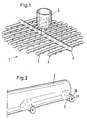
- the distribution device 1 shown in Figure 1 exists made of glass and has the following structure: a variety of parallel manifolds 2 with nozzles 3 that are made according to the invention from pieces of glass tube; an inlet pipe 4 upstream of the pipes 2; and a Bell 5, which supplied the liquid to be distributed can and in which the liquid is up to one depending on the discharge rate.
- the nozzles are all arranged on the same level, so that result in the same exit conditions.
- the 2 shows a distribution pipe 2 lying on the side through which two glass tube pieces 3 serving as nozzles Melting the glass are appropriate.
- the the End opening 30 containing outlet opening 31 of the Pipe section 3 is an untreated milling cut or Broken glass surface. Thanks to this feature that the edges of the Outlet openings 31 by means of a milling cut or Glass breakage formed and otherwise untreated edges are formed, are practically the same for all nozzles 3 Exit conditions for the liquid to be distributed in front. Thus there is an even distribution of Liquid guaranteed without special effort.
- With Advantage is used for the production of Glass tube pieces 3 commercially available capillary tubes, one have a precisely formed inner diameter. The Glass tube pieces 3 are each after melting milled the same length.
- the glass tube pieces 3 can also in the distribution tube 2 be arranged so that their entry points (also with Broken surfaces or milled cut surfaces) in the Center area of tube 2 come to rest. At this Arrangement can be found below the entry points Remove dirt particles. Nozzle channels that are less sensitive to dirt Dirt particles are burdened, and the appearance of Impairment of the flow is reduced.
- Support points are not shown in FIG The purpose is to place the device in the column To put on the carrier. Such support points exist with Benefit from tubular or bell-shaped parts that on the lower side of the distribution pipes 2 are melted.
- the distribution pipes 2 can also be extruded Be made of plastic pipes.
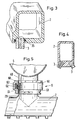
- Fig.3 shows a Exemplary embodiment: The glass tube pieces 3 are in addition trained openings inserted and with a Sealing ring 35 fixed. Other possible materials instead of plastic there are ceramic materials.
- a number of nozzles 3 may be provided.
- the exemplary embodiment shown are the nozzles 3 staggered; and they are inclined instead of vertical aligned.
- the distribution device according to the invention can also be made in several parts, the parts being detachable are interconnected.
- Fig. 5 shows such Connection 6 between a distribution pipe 2 with nozzles 3 and an inlet pipe 4.
- a nozzle 20 of the pipe 2 is with a nozzle 40 of the other tube 2b.
- the Connection 6 consists of the following components together: an upper part 60 and a lower part 61, which are screwed together via threaded pieces; one Intermediate piece 62; as well as two sealing rings with which the edges of the two connecting pieces 20 and 40 on the one hand against be sealed on the outside and on the other hand a tight Connection made with the intermediate piece 62 becomes.
- the Distributors in the form of composite devices be constructed.
- For the diameter of the nozzle exit surfaces 31 are Values in the range between around 0.3 mm and 10 mm intended.
- the free-standing length is advantageous the glass tube pieces 3 around 10 to 15 mm.
- the distribution device according to the invention is special advantageous.
- the nozzles become like this arranged that the pack with respect to the liquid or fluid distribution of the same size or largely the same large areas can be assigned. At the edge there are usually deviations from one Equal distribution.
- the distribution device consists entirely of Glass or glass and for example plastic; she contains no metallic parts. Columns with such Distribution devices are particularly well suited for Carrying out a mass exchange between a gas and a liquid, one of these phases or both contain a substance that is corrosive to metals acts. Of course, in such a column the other internals are made of materials that are inert with regard to the substances to be treated.
Landscapes
- Chemical & Material Sciences (AREA)
- Chemical Kinetics & Catalysis (AREA)
- Engineering & Computer Science (AREA)
- Analytical Chemistry (AREA)
- General Chemical & Material Sciences (AREA)
- Oil, Petroleum & Natural Gas (AREA)
- Vaporization, Distillation, Condensation, Sublimation, And Cold Traps (AREA)
- Feeding, Discharge, Calcimining, Fusing, And Gas-Generation Devices (AREA)
- Physical Or Chemical Processes And Apparatus (AREA)
- Nozzles (AREA)
- Treatment Of Liquids With Adsorbents In General (AREA)
Claims (10)
- Dispositif répartiteur pour une colonne, avec un système de tuyaux répartiteurs (2, 4) et des buses (3) pour un fluide, les orifices de sortie (31) des buses étant disposés de préférence tous au même niveau,
caractérisé en ce qu'au moins une partie des buses est fabriquée à partir de bouts de tuyau de verre (3) identiques et en ce que chaque orifice de sortie présente un bord qui est constitué par une arête formée au moyen d'une coupe de fraisage et non traitée autrement ou une arête de cassure de verre non traitée. - Dispositif répartiteur selon la revendication 1, caractérisé en ce que des bouts de tuyau de verre (3) sont appliqués par fusion sur au moins un tuyau répartiteur (2) en verre et les bouts de tuyau de verre ont été fraisés à la même longueur après l'application.
- Dispositif répartiteur selon la revendication 2, caractérisé en ce qu'un tuyau d'arrivée (4) et le système de tuyaux répartiteurs (2) forment une unité (1) fabriquée en verre.
- Dispositif répartiteur selon la revendication 2, caractérisé en ce qu'il est conçu en plusieurs parties et en ce que les parties (2, 4) sont reliées entre elles de façon amovible.
- Dispositif répartiteur selon l'une quelconque des revendications 1 à 4, caractérisé en ce que le diamètre des buses (3) se situe dans la plage comprise entre environ 0,3 mm et 10 mm.
- Dispositif répartiteur selon l'une quelconque des revendications 1 à 5, caractérisé en ce que les bouts de tuyau de verre (3) sont environ 10 à 15 mm de longueur dans la zone libre.
- Dispositif répartiteur selon l'une quelconque des revendications 1 à 7, caractérisé en ce que les bouts de tuyau de verre (3) sont disposés dans le tuyau répartiteur (2) de telle sorte que leurs points d'entrée arrivent dans la zone centrale du tuyau.
- Colonne avec un dispositif répartiteur selon l'une quelconque des revendications 1 à 7, avec un garnissage structuré de façon ordonnée et avec des buses (3), qui sont disposées de telle sorte que des zones partielles de grandeur identique peuvent être attribuées au garnissage en ce qui concerne la répartition du fluide et une grande partie des buses.
- Utilisation d'une colonne selon la revendication 8 pour la réalisation d'un échange de matières entre un gaz et un liquide, qui est amené à l'emballage au moyen du dispositif répartiteur, le liquide agissant de façon corrosive sur des métaux et le garnissage étant à base d'un matériau inerte par rapport au liquide.
- Utilisation d'un dispositif répartiteur selon l'une quelconque des revendications 1 à 7, en particulier pour la réalisation d'une sorption, un premier liquide ou un gaz étant introduit avec le dispositif répartiteur dans une colonne remplie d'un second liquide.
Priority Applications (9)
| Application Number | Priority Date | Filing Date | Title |
|---|---|---|---|
| ES97810307T ES2210483T3 (es) | 1997-05-16 | 1997-05-16 | Dispositivo distribuidor para una columna. |
| EP97810307A EP0878221B1 (fr) | 1997-05-16 | 1997-05-16 | Dispositif de distribution pour des colonnes |
| DE59710959T DE59710959D1 (de) | 1997-05-16 | 1997-05-16 | Verteilvorrichtung für eine Kolonne |
| CA002233354A CA2233354C (fr) | 1997-05-16 | 1998-03-30 | Dispositif de distribution pour colonne |
| JP10110848A JPH10323555A (ja) | 1997-05-16 | 1998-04-21 | カラム用ディストリビュータ装置 |
| US09/074,524 US6042090A (en) | 1997-05-16 | 1998-05-07 | Distributor device for a column |
| CN98108915A CN1104929C (zh) | 1997-05-16 | 1998-05-15 | 塔用分配器装置 |
| BR9801186-3A BR9801186A (pt) | 1997-05-16 | 1998-05-15 | Dispositivo distribuidor para uma coluna |
| RU98109108A RU2146553C1 (ru) | 1997-05-16 | 1998-05-15 | Распределительное устройство для абсорбционной колонны |
Applications Claiming Priority (1)
| Application Number | Priority Date | Filing Date | Title |
|---|---|---|---|
| EP97810307A EP0878221B1 (fr) | 1997-05-16 | 1997-05-16 | Dispositif de distribution pour des colonnes |
Publications (2)
| Publication Number | Publication Date |
|---|---|
| EP0878221A1 EP0878221A1 (fr) | 1998-11-18 |
| EP0878221B1 true EP0878221B1 (fr) | 2003-11-05 |
Family
ID=8230234
Family Applications (1)
| Application Number | Title | Priority Date | Filing Date |
|---|---|---|---|
| EP97810307A Expired - Lifetime EP0878221B1 (fr) | 1997-05-16 | 1997-05-16 | Dispositif de distribution pour des colonnes |
Country Status (9)
| Country | Link |
|---|---|
| US (1) | US6042090A (fr) |
| EP (1) | EP0878221B1 (fr) |
| JP (1) | JPH10323555A (fr) |
| CN (1) | CN1104929C (fr) |
| BR (1) | BR9801186A (fr) |
| CA (1) | CA2233354C (fr) |
| DE (1) | DE59710959D1 (fr) |
| ES (1) | ES2210483T3 (fr) |
| RU (1) | RU2146553C1 (fr) |
Cited By (1)
| Publication number | Priority date | Publication date | Assignee | Title |
|---|---|---|---|---|
| US11167221B2 (en) | 2017-04-13 | 2021-11-09 | Saipem S.P.A. | Liquid double distribution device of use in particular in an apparatus in which a liquid phase flows under gravity |
Families Citing this family (17)
| Publication number | Priority date | Publication date | Assignee | Title |
|---|---|---|---|---|
| FR2842435B1 (fr) * | 2002-07-16 | 2004-09-24 | Inst Francais Du Petrole | Dispositif de melange et de distribution d'un fluide dense et d'un fluide leger place en amont d'un lit granulaire et son utilisation en ecoulement descendant |
| AU2003284210A1 (en) * | 2002-10-15 | 2004-05-04 | Vast Power Systems, Inc. | Method and apparatus for mixing fluids |
| ATE457796T1 (de) * | 2002-10-23 | 2010-03-15 | Sulzer Chemtech Ag | Einrichtung in einer verfahrenstechnischen kolonne |
| US20050056313A1 (en) * | 2003-09-12 | 2005-03-17 | Hagen David L. | Method and apparatus for mixing fluids |
| US7125004B2 (en) * | 2003-12-15 | 2006-10-24 | Koch-Glitsch, Lp | Liquid distributor for use in mass transfer column |
| DE602006017238D1 (de) * | 2006-10-23 | 2010-11-11 | Eric Verdroncken | Methode um einem Gasstrom mit festen oder flüssigen Partikeln zu säubern |
| DE102007019816A1 (de) | 2007-04-26 | 2008-10-30 | Linde Ag | Sammler-Verteiler-Kombination |
| US7901641B2 (en) * | 2008-07-22 | 2011-03-08 | Uop Llc | Sprayer for at least one fluid |
| EP2397204B1 (fr) * | 2010-06-21 | 2016-06-08 | Neste Oyj | Section d'alimentation d'une colonne de séparation |
| CN101865574B (zh) | 2010-06-21 | 2013-01-30 | 三花控股集团有限公司 | 换热器 |
| CN102564204B (zh) * | 2010-12-08 | 2016-04-06 | 杭州三花微通道换热器有限公司 | 制冷剂分配装置和具有它的换热器 |
| FR2989594B1 (fr) * | 2012-04-18 | 2015-04-24 | IFP Energies Nouvelles | Plateau distributeur pour colonne de contact gaz/liquide offshore |
| US8894048B2 (en) * | 2012-07-17 | 2014-11-25 | Dow Global Technologies Llc | Gas diffuser |
| CN105056839A (zh) * | 2015-08-13 | 2015-11-18 | 天津市博爱制药有限公司 | 一种液体分散加料装置 |
| SE543267C2 (en) * | 2019-03-14 | 2020-11-10 | Camfil Ab | Aerosol distribution in filter testing systems |
| CN110227372A (zh) * | 2019-07-13 | 2019-09-13 | 曾凤英 | 一种原料加工用高效混液装置 |
| CN112295253B (zh) * | 2020-10-30 | 2022-03-18 | 上海化工研究院有限公司 | 一种毛细管液相分布器及精馏柱 |
Family Cites Families (10)
| Publication number | Priority date | Publication date | Assignee | Title |
|---|---|---|---|---|
| US3419251A (en) * | 1965-06-21 | 1968-12-31 | Us Stoneware Inc | Distributor |
| GB1142956A (en) * | 1965-06-21 | 1969-02-12 | Us Stoneware Inc | Distributor |
| DE2923198C3 (de) * | 1979-06-08 | 1982-04-01 | Jenaer Glaswerk Schott & Gen., 6500 Mainz | Flüssigkeitsverteiler für Stoffaustauschkolonnen |
| US4320072A (en) * | 1981-02-27 | 1982-03-16 | Ecodyne Corporation | Cooling tower spray nozzle |
| DE8324619U1 (de) * | 1983-08-27 | 1984-01-12 | Dornier System Gmbh, 7990 Friedrichshafen | Vorrichtung zur aufkonzentrierung von waessrigen loesungen |
| US4776989A (en) * | 1983-09-19 | 1988-10-11 | The Dow Chemical Company | Method and apparatus for liquid feed to liqiud distributors in fluid-liquid contacting towers |
| US5601688A (en) * | 1990-02-14 | 1997-02-11 | Ormat Industries Ltd. | Method of and means for spraying droplets |
| CN2173244Y (zh) * | 1993-10-27 | 1994-08-03 | 济南市第四人民医院 | 半自动酶标洗板器 |
| TW259725B (fr) * | 1994-04-11 | 1995-10-11 | Mitsubishi Heavy Ind Ltd | |
| US5679290A (en) * | 1996-09-16 | 1997-10-21 | Cameron; Gordon M. | Packed absorption towers |
-
1997
- 1997-05-16 ES ES97810307T patent/ES2210483T3/es not_active Expired - Lifetime
- 1997-05-16 DE DE59710959T patent/DE59710959D1/de not_active Expired - Fee Related
- 1997-05-16 EP EP97810307A patent/EP0878221B1/fr not_active Expired - Lifetime
-
1998
- 1998-03-30 CA CA002233354A patent/CA2233354C/fr not_active Expired - Fee Related
- 1998-04-21 JP JP10110848A patent/JPH10323555A/ja active Pending
- 1998-05-07 US US09/074,524 patent/US6042090A/en not_active Expired - Fee Related
- 1998-05-15 CN CN98108915A patent/CN1104929C/zh not_active Expired - Fee Related
- 1998-05-15 BR BR9801186-3A patent/BR9801186A/pt not_active IP Right Cessation
- 1998-05-15 RU RU98109108A patent/RU2146553C1/ru active
Cited By (1)
| Publication number | Priority date | Publication date | Assignee | Title |
|---|---|---|---|---|
| US11167221B2 (en) | 2017-04-13 | 2021-11-09 | Saipem S.P.A. | Liquid double distribution device of use in particular in an apparatus in which a liquid phase flows under gravity |
Also Published As
| Publication number | Publication date |
|---|---|
| CA2233354A1 (fr) | 1998-11-16 |
| DE59710959D1 (de) | 2003-12-11 |
| CN1203115A (zh) | 1998-12-30 |
| EP0878221A1 (fr) | 1998-11-18 |
| CA2233354C (fr) | 2002-06-25 |
| US6042090A (en) | 2000-03-28 |
| ES2210483T3 (es) | 2004-07-01 |
| JPH10323555A (ja) | 1998-12-08 |
| BR9801186A (pt) | 2000-05-09 |
| RU2146553C1 (ru) | 2000-03-20 |
| CN1104929C (zh) | 2003-04-09 |
Similar Documents
| Publication | Publication Date | Title |
|---|---|---|
| EP0878221B1 (fr) | Dispositif de distribution pour des colonnes | |
| DE2943687C2 (de) | Trogartige Vorrichtung zum Sammeln und Verteilen der Flüssigkeit für eine Gegenstromkolonne | |
| DE2224320C2 (de) | Ausgabekopf für Bewässerungs- oder Berieselungsanlagen | |
| EP0282753B2 (fr) | Dispositif pour la distribution uniforme d'un liquide sur des parties d'échanges d'une colonne d'échange de matière et de chaleur | |
| EP1038562B1 (fr) | Dispositif pour collecter et distribuer des liquides dans une colonne | |
| EP1013324A2 (fr) | Colonne à contre-courant avec distributeur de liquide | |
| EP0176891A2 (fr) | Colonne chromatographique | |
| DE10341896A1 (de) | Mehrphasen-Flüssigkeitsverteiler für einen Rieselbettreaktor | |
| DE19837569B4 (de) | Verfahren zur Reinigung von Filterkerzen eines Kerzenfilters | |
| CH655252A5 (de) | Ausstroemduese, mit einer muendung fuer ein stroemungsmedium, das feststoffe enthalten kann. | |
| EP0231841A1 (fr) | Dispositif pour la distribution uniforme d'un liquide contenant des matières solides sur une section transversale | |
| DE3940334A1 (de) | Sieb fuer drucksortierer fuer fasersuspensionen | |
| EP0430926B1 (fr) | Filière | |
| DE10051523A1 (de) | Vorrichtung zur Verteilung einer Flüssigkeit in einer Gegenstrom-Kolonne | |
| EP0953205A1 (fr) | Dispositif de traitement de substrats | |
| DE19541436C2 (de) | Anlage zur Behandlung von Gegenständen in einem Prozeßtank | |
| EP1928567A1 (fr) | Dispositif et procede de repartition de deux liquides non miscibles | |
| DE2808951A1 (de) | Einspritzduese fuer eine kunststoff- spritzgussmaschine | |
| EP0111941B1 (fr) | Plateau de colonnes de distillation et/ou d'absorption | |
| DE102004056419A1 (de) | Geordnete Packung für Wärme und/oder Stoffaustausch | |
| DE4237350C2 (de) | Verfahren zum Stoffübertragen sowie Vorrichtung zur Durchführung des Verfahrens | |
| EP0582024B1 (fr) | Utilisation d'un dispositif pour la séparation des particules solides d'un fluide | |
| EP1005889B1 (fr) | Distributeur de liquide pour des colonnes garnies | |
| DE2517729C2 (de) | Kaltfangvorrichtung zum Reinigen eines Flüssigkeitsstroms | |
| DE3714592C3 (de) | Kraftfahrzeug-Sicherheitsrohr aus thermoplastischem Kunststoff |
Legal Events
| Date | Code | Title | Description |
|---|---|---|---|
| PUAI | Public reference made under article 153(3) epc to a published international application that has entered the european phase |
Free format text: ORIGINAL CODE: 0009012 |
|
| AK | Designated contracting states |
Kind code of ref document: A1 Designated state(s): CH DE ES FR GB IT LI NL |
|
| AX | Request for extension of the european patent |
Free format text: AL;LT;LV;RO;SI |
|
| 17P | Request for examination filed |
Effective date: 19990422 |
|
| AKX | Designation fees paid |
Free format text: AT BE CH DE DK ES FI LI |
|
| RBV | Designated contracting states (corrected) |
Designated state(s): CH DE ES FR GB IT LI NL |
|
| GRAH | Despatch of communication of intention to grant a patent |
Free format text: ORIGINAL CODE: EPIDOS IGRA |
|
| GRAS | Grant fee paid |
Free format text: ORIGINAL CODE: EPIDOSNIGR3 |
|
| GRAA | (expected) grant |
Free format text: ORIGINAL CODE: 0009210 |
|
| AK | Designated contracting states |
Kind code of ref document: B1 Designated state(s): CH DE ES FR GB IT LI NL |
|
| PG25 | Lapsed in a contracting state [announced via postgrant information from national office to epo] |
Ref country code: NL Free format text: LAPSE BECAUSE OF FAILURE TO SUBMIT A TRANSLATION OF THE DESCRIPTION OR TO PAY THE FEE WITHIN THE PRESCRIBED TIME-LIMIT Effective date: 20031105 |
|
| REG | Reference to a national code |
Ref country code: GB Ref legal event code: FG4D Free format text: NOT ENGLISH |
|
| REG | Reference to a national code |
Ref country code: CH Ref legal event code: EP |
|
| GBT | Gb: translation of ep patent filed (gb section 77(6)(a)/1977) |
Effective date: 20031105 |
|
| REF | Corresponds to: |
Ref document number: 59710959 Country of ref document: DE Date of ref document: 20031211 Kind code of ref document: P |
|
| NLV1 | Nl: lapsed or annulled due to failure to fulfill the requirements of art. 29p and 29m of the patents act | ||
| PG25 | Lapsed in a contracting state [announced via postgrant information from national office to epo] |
Ref country code: LI Free format text: LAPSE BECAUSE OF NON-PAYMENT OF DUE FEES Effective date: 20040531 Ref country code: CH Free format text: LAPSE BECAUSE OF NON-PAYMENT OF DUE FEES Effective date: 20040531 |
|
| REG | Reference to a national code |
Ref country code: ES Ref legal event code: FG2A Ref document number: 2210483 Country of ref document: ES Kind code of ref document: T3 |
|
| ET | Fr: translation filed | ||
| PLBE | No opposition filed within time limit |
Free format text: ORIGINAL CODE: 0009261 |
|
| STAA | Information on the status of an ep patent application or granted ep patent |
Free format text: STATUS: NO OPPOSITION FILED WITHIN TIME LIMIT |
|
| 26N | No opposition filed |
Effective date: 20040806 |
|
| REG | Reference to a national code |
Ref country code: CH Ref legal event code: PL |
|
| PGFP | Annual fee paid to national office [announced via postgrant information from national office to epo] |
Ref country code: ES Payment date: 20090521 Year of fee payment: 13 |
|
| PGFP | Annual fee paid to national office [announced via postgrant information from national office to epo] |
Ref country code: IT Payment date: 20090527 Year of fee payment: 13 Ref country code: FR Payment date: 20090513 Year of fee payment: 13 Ref country code: DE Payment date: 20090525 Year of fee payment: 13 |
|
| PGFP | Annual fee paid to national office [announced via postgrant information from national office to epo] |
Ref country code: GB Payment date: 20090522 Year of fee payment: 13 |
|
| GBPC | Gb: european patent ceased through non-payment of renewal fee |
Effective date: 20100516 |
|
| REG | Reference to a national code |
Ref country code: FR Ref legal event code: ST Effective date: 20110131 |
|
| PG25 | Lapsed in a contracting state [announced via postgrant information from national office to epo] |
Ref country code: IT Free format text: LAPSE BECAUSE OF NON-PAYMENT OF DUE FEES Effective date: 20100516 |
|
| PG25 | Lapsed in a contracting state [announced via postgrant information from national office to epo] |
Ref country code: DE Free format text: LAPSE BECAUSE OF NON-PAYMENT OF DUE FEES Effective date: 20101201 |
|
| PG25 | Lapsed in a contracting state [announced via postgrant information from national office to epo] |
Ref country code: FR Free format text: LAPSE BECAUSE OF NON-PAYMENT OF DUE FEES Effective date: 20100531 |
|
| REG | Reference to a national code |
Ref country code: ES Ref legal event code: FD2A Effective date: 20110715 |
|
| PG25 | Lapsed in a contracting state [announced via postgrant information from national office to epo] |
Ref country code: ES Free format text: LAPSE BECAUSE OF NON-PAYMENT OF DUE FEES Effective date: 20110705 Ref country code: GB Free format text: LAPSE BECAUSE OF NON-PAYMENT OF DUE FEES Effective date: 20100516 |
|
| PG25 | Lapsed in a contracting state [announced via postgrant information from national office to epo] |
Ref country code: ES Free format text: LAPSE BECAUSE OF NON-PAYMENT OF DUE FEES Effective date: 20100517 |