EP0877401B1 - In einem Schritt Ultraschall-beschichtetes Substrat zur Verwendung in einem Kondensator - Google Patents
In einem Schritt Ultraschall-beschichtetes Substrat zur Verwendung in einem Kondensator Download PDFInfo
- Publication number
- EP0877401B1 EP0877401B1 EP19980303434 EP98303434A EP0877401B1 EP 0877401 B1 EP0877401 B1 EP 0877401B1 EP 19980303434 EP19980303434 EP 19980303434 EP 98303434 A EP98303434 A EP 98303434A EP 0877401 B1 EP0877401 B1 EP 0877401B1
- Authority
- EP
- European Patent Office
- Prior art keywords
- substrate
- coating
- capacitor
- aerosol
- pseudocapacitive
- Prior art date
- Legal status (The legal status is an assumption and is not a legal conclusion. Google has not performed a legal analysis and makes no representation as to the accuracy of the status listed.)
- Expired - Lifetime
Links
- 239000000758 substrate Substances 0.000 title claims description 116
- 239000003990 capacitor Substances 0.000 title claims description 62
- 238000000576 coating method Methods 0.000 claims description 82
- 239000011248 coating agent Substances 0.000 claims description 71
- 239000000443 aerosol Substances 0.000 claims description 48
- 239000002184 metal Substances 0.000 claims description 44
- 229910052751 metal Inorganic materials 0.000 claims description 43
- 238000000034 method Methods 0.000 claims description 38
- 239000002243 precursor Substances 0.000 claims description 31
- PXHVJJICTQNCMI-UHFFFAOYSA-N Nickel Chemical compound [Ni] PXHVJJICTQNCMI-UHFFFAOYSA-N 0.000 claims description 26
- KDLHZDBZIXYQEI-UHFFFAOYSA-N Palladium Chemical compound [Pd] KDLHZDBZIXYQEI-UHFFFAOYSA-N 0.000 claims description 24
- 150000002736 metal compounds Chemical class 0.000 claims description 24
- BASFCYQUMIYNBI-UHFFFAOYSA-N platinum Chemical compound [Pt] BASFCYQUMIYNBI-UHFFFAOYSA-N 0.000 claims description 24
- XEEYBQQBJWHFJM-UHFFFAOYSA-N Iron Chemical compound [Fe] XEEYBQQBJWHFJM-UHFFFAOYSA-N 0.000 claims description 20
- 229910052715 tantalum Inorganic materials 0.000 claims description 19
- GUVRBAGPIYLISA-UHFFFAOYSA-N tantalum atom Chemical compound [Ta] GUVRBAGPIYLISA-UHFFFAOYSA-N 0.000 claims description 19
- RTAQQCXQSZGOHL-UHFFFAOYSA-N Titanium Chemical compound [Ti] RTAQQCXQSZGOHL-UHFFFAOYSA-N 0.000 claims description 15
- 238000000151 deposition Methods 0.000 claims description 15
- 239000000203 mixture Substances 0.000 claims description 15
- 229910052719 titanium Inorganic materials 0.000 claims description 15
- 239000010936 titanium Substances 0.000 claims description 15
- KJTLSVCANCCWHF-UHFFFAOYSA-N Ruthenium Chemical compound [Ru] KJTLSVCANCCWHF-UHFFFAOYSA-N 0.000 claims description 14
- QCWXUUIWCKQGHC-UHFFFAOYSA-N Zirconium Chemical compound [Zr] QCWXUUIWCKQGHC-UHFFFAOYSA-N 0.000 claims description 14
- 229910052758 niobium Inorganic materials 0.000 claims description 14
- 239000010955 niobium Substances 0.000 claims description 14
- GUCVJGMIXFAOAE-UHFFFAOYSA-N niobium atom Chemical compound [Nb] GUCVJGMIXFAOAE-UHFFFAOYSA-N 0.000 claims description 14
- 229910052707 ruthenium Inorganic materials 0.000 claims description 14
- 229910052726 zirconium Inorganic materials 0.000 claims description 14
- ZOKXTWBITQBERF-UHFFFAOYSA-N Molybdenum Chemical compound [Mo] ZOKXTWBITQBERF-UHFFFAOYSA-N 0.000 claims description 13
- 229910052750 molybdenum Inorganic materials 0.000 claims description 13
- 239000011733 molybdenum Substances 0.000 claims description 13
- 229910052759 nickel Inorganic materials 0.000 claims description 13
- 150000004767 nitrides Chemical class 0.000 claims description 13
- WFKWXMTUELFFGS-UHFFFAOYSA-N tungsten Chemical compound [W] WFKWXMTUELFFGS-UHFFFAOYSA-N 0.000 claims description 13
- 229910052721 tungsten Inorganic materials 0.000 claims description 13
- 239000010937 tungsten Substances 0.000 claims description 13
- 229910052735 hafnium Inorganic materials 0.000 claims description 12
- VBJZVLUMGGDVMO-UHFFFAOYSA-N hafnium atom Chemical compound [Hf] VBJZVLUMGGDVMO-UHFFFAOYSA-N 0.000 claims description 12
- 229910052763 palladium Inorganic materials 0.000 claims description 12
- 239000002245 particle Substances 0.000 claims description 12
- 229910052697 platinum Inorganic materials 0.000 claims description 12
- 229910052720 vanadium Inorganic materials 0.000 claims description 12
- 229910017052 cobalt Inorganic materials 0.000 claims description 11
- 239000010941 cobalt Substances 0.000 claims description 11
- GUTLYIVDDKVIGB-UHFFFAOYSA-N cobalt atom Chemical compound [Co] GUTLYIVDDKVIGB-UHFFFAOYSA-N 0.000 claims description 11
- 239000003792 electrolyte Substances 0.000 claims description 11
- JMANVNJQNLATNU-UHFFFAOYSA-N oxalonitrile Chemical compound N#CC#N JMANVNJQNLATNU-UHFFFAOYSA-N 0.000 claims description 11
- 229910052741 iridium Inorganic materials 0.000 claims description 10
- GKOZUEZYRPOHIO-UHFFFAOYSA-N iridium atom Chemical compound [Ir] GKOZUEZYRPOHIO-UHFFFAOYSA-N 0.000 claims description 10
- 229910052742 iron Inorganic materials 0.000 claims description 10
- WPBNNNQJVZRUHP-UHFFFAOYSA-L manganese(2+);methyl n-[[2-(methoxycarbonylcarbamothioylamino)phenyl]carbamothioyl]carbamate;n-[2-(sulfidocarbothioylamino)ethyl]carbamodithioate Chemical compound [Mn+2].[S-]C(=S)NCCNC([S-])=S.COC(=O)NC(=S)NC1=CC=CC=C1NC(=S)NC(=O)OC WPBNNNQJVZRUHP-UHFFFAOYSA-L 0.000 claims description 10
- 229910052703 rhodium Inorganic materials 0.000 claims description 10
- 239000010948 rhodium Substances 0.000 claims description 10
- MHOVAHRLVXNVSD-UHFFFAOYSA-N rhodium atom Chemical compound [Rh] MHOVAHRLVXNVSD-UHFFFAOYSA-N 0.000 claims description 10
- 229910052762 osmium Inorganic materials 0.000 claims description 9
- SYQBFIAQOQZEGI-UHFFFAOYSA-N osmium atom Chemical compound [Os] SYQBFIAQOQZEGI-UHFFFAOYSA-N 0.000 claims description 9
- OKKJLVBELUTLKV-UHFFFAOYSA-N Methanol Chemical compound OC OKKJLVBELUTLKV-UHFFFAOYSA-N 0.000 claims description 6
- 229910052782 aluminium Inorganic materials 0.000 claims description 6
- XAGFODPZIPBFFR-UHFFFAOYSA-N aluminium Chemical compound [Al] XAGFODPZIPBFFR-UHFFFAOYSA-N 0.000 claims description 6
- BQCADISMDOOEFD-UHFFFAOYSA-N Silver Chemical compound [Ag] BQCADISMDOOEFD-UHFFFAOYSA-N 0.000 claims description 5
- PCHJSUWPFVWCPO-UHFFFAOYSA-N gold Chemical compound [Au] PCHJSUWPFVWCPO-UHFFFAOYSA-N 0.000 claims description 5
- 229910052737 gold Inorganic materials 0.000 claims description 5
- 239000010931 gold Substances 0.000 claims description 5
- QSHDDOUJBYECFT-UHFFFAOYSA-N mercury Chemical compound [Hg] QSHDDOUJBYECFT-UHFFFAOYSA-N 0.000 claims description 5
- 229910052753 mercury Inorganic materials 0.000 claims description 5
- 229910052709 silver Inorganic materials 0.000 claims description 5
- 239000004332 silver Substances 0.000 claims description 5
- KRHYYFGTRYWZRS-UHFFFAOYSA-N Fluorane Chemical compound F KRHYYFGTRYWZRS-UHFFFAOYSA-N 0.000 claims description 4
- VEXZGXHMUGYJMC-UHFFFAOYSA-N Hydrochloric acid Chemical compound Cl VEXZGXHMUGYJMC-UHFFFAOYSA-N 0.000 claims description 4
- 238000010438 heat treatment Methods 0.000 claims description 4
- RYGMFSIKBFXOCR-UHFFFAOYSA-N Copper Chemical compound [Cu] RYGMFSIKBFXOCR-UHFFFAOYSA-N 0.000 claims description 3
- QVGXLLKOCUKJST-UHFFFAOYSA-N atomic oxygen Chemical compound [O] QVGXLLKOCUKJST-UHFFFAOYSA-N 0.000 claims description 3
- 238000005422 blasting Methods 0.000 claims description 3
- 229910052802 copper Inorganic materials 0.000 claims description 3
- 239000010949 copper Substances 0.000 claims description 3
- 229910001867 inorganic solvent Inorganic materials 0.000 claims description 3
- 239000003049 inorganic solvent Substances 0.000 claims description 3
- 239000001301 oxygen Substances 0.000 claims description 3
- 229910052760 oxygen Inorganic materials 0.000 claims description 3
- 229910001220 stainless steel Inorganic materials 0.000 claims description 3
- 239000010935 stainless steel Substances 0.000 claims description 3
- VYZAMTAEIAYCRO-UHFFFAOYSA-N Chromium Chemical compound [Cr] VYZAMTAEIAYCRO-UHFFFAOYSA-N 0.000 claims description 2
- XUIMIQQOPSSXEZ-UHFFFAOYSA-N Silicon Chemical compound [Si] XUIMIQQOPSSXEZ-UHFFFAOYSA-N 0.000 claims description 2
- HCHKCACWOHOZIP-UHFFFAOYSA-N Zinc Chemical compound [Zn] HCHKCACWOHOZIP-UHFFFAOYSA-N 0.000 claims description 2
- SWLVFNYSXGMGBS-UHFFFAOYSA-N ammonium bromide Chemical compound [NH4+].[Br-] SWLVFNYSXGMGBS-UHFFFAOYSA-N 0.000 claims description 2
- 230000001680 brushing effect Effects 0.000 claims description 2
- 229910052804 chromium Inorganic materials 0.000 claims description 2
- 239000011651 chromium Substances 0.000 claims description 2
- 229910052732 germanium Inorganic materials 0.000 claims description 2
- GNPVGFCGXDBREM-UHFFFAOYSA-N germanium atom Chemical compound [Ge] GNPVGFCGXDBREM-UHFFFAOYSA-N 0.000 claims description 2
- -1 hafinium Chemical compound 0.000 claims description 2
- 238000001020 plasma etching Methods 0.000 claims description 2
- 238000007790 scraping Methods 0.000 claims description 2
- 229910052710 silicon Inorganic materials 0.000 claims description 2
- 239000010703 silicon Substances 0.000 claims description 2
- 229910052725 zinc Inorganic materials 0.000 claims description 2
- 239000011701 zinc Substances 0.000 claims description 2
- LEONUFNNVUYDNQ-UHFFFAOYSA-N vanadium atom Chemical compound [V] LEONUFNNVUYDNQ-UHFFFAOYSA-N 0.000 claims 6
- 239000002253 acid Substances 0.000 claims 4
- RFWNYPJLUXDHQH-UHFFFAOYSA-N [V].[Os] Chemical compound [V].[Os] RFWNYPJLUXDHQH-UHFFFAOYSA-N 0.000 claims 1
- IXQWNVPHFNLUGD-UHFFFAOYSA-N iron titanium Chemical compound [Ti].[Fe] IXQWNVPHFNLUGD-UHFFFAOYSA-N 0.000 claims 1
- 239000000243 solution Substances 0.000 description 34
- 239000003153 chemical reaction reagent Substances 0.000 description 23
- 239000003595 mist Substances 0.000 description 20
- 239000007789 gas Substances 0.000 description 17
- 239000010408 film Substances 0.000 description 14
- 230000008021 deposition Effects 0.000 description 12
- 239000000463 material Substances 0.000 description 12
- 229910001925 ruthenium oxide Inorganic materials 0.000 description 12
- WOCIAKWEIIZHES-UHFFFAOYSA-N ruthenium(iv) oxide Chemical compound O=[Ru]=O WOCIAKWEIIZHES-UHFFFAOYSA-N 0.000 description 12
- 238000005507 spraying Methods 0.000 description 11
- 150000003839 salts Chemical class 0.000 description 9
- 239000002904 solvent Substances 0.000 description 9
- 239000007921 spray Substances 0.000 description 8
- 239000011888 foil Substances 0.000 description 7
- 238000000889 atomisation Methods 0.000 description 6
- 150000002739 metals Chemical class 0.000 description 6
- GPPXJZIENCGNKB-UHFFFAOYSA-N vanadium Chemical compound [V]#[V] GPPXJZIENCGNKB-UHFFFAOYSA-N 0.000 description 6
- 150000001875 compounds Chemical class 0.000 description 5
- 238000004146 energy storage Methods 0.000 description 5
- 150000002500 ions Chemical class 0.000 description 5
- YLPJWCDYYXQCIP-UHFFFAOYSA-N nitroso nitrate;ruthenium Chemical compound [Ru].[O-][N+](=O)ON=O YLPJWCDYYXQCIP-UHFFFAOYSA-N 0.000 description 5
- XLYOFNOQVPJJNP-UHFFFAOYSA-N water Substances O XLYOFNOQVPJJNP-UHFFFAOYSA-N 0.000 description 5
- 238000004140 cleaning Methods 0.000 description 4
- 238000002484 cyclic voltammetry Methods 0.000 description 4
- 238000009501 film coating Methods 0.000 description 4
- 239000007788 liquid Substances 0.000 description 4
- KFZMGEQAYNKOFK-UHFFFAOYSA-N Isopropanol Chemical compound CC(C)O KFZMGEQAYNKOFK-UHFFFAOYSA-N 0.000 description 3
- 229910002651 NO3 Inorganic materials 0.000 description 3
- NHNBFGGVMKEFGY-UHFFFAOYSA-N Nitrate Chemical compound [O-][N+]([O-])=O NHNBFGGVMKEFGY-UHFFFAOYSA-N 0.000 description 3
- KWYUFKZDYYNOTN-UHFFFAOYSA-M Potassium hydroxide Chemical compound [OH-].[K+] KWYUFKZDYYNOTN-UHFFFAOYSA-M 0.000 description 3
- 150000001768 cations Chemical class 0.000 description 3
- 238000006243 chemical reaction Methods 0.000 description 3
- 238000007598 dipping method Methods 0.000 description 3
- 239000007888 film coating Substances 0.000 description 3
- 238000004519 manufacturing process Methods 0.000 description 3
- 229910044991 metal oxide Inorganic materials 0.000 description 3
- 150000004706 metal oxides Chemical class 0.000 description 3
- 150000002823 nitrates Chemical class 0.000 description 3
- 239000003960 organic solvent Substances 0.000 description 3
- 239000007787 solid Substances 0.000 description 3
- XKRFYHLGVUSROY-UHFFFAOYSA-N Argon Chemical compound [Ar] XKRFYHLGVUSROY-UHFFFAOYSA-N 0.000 description 2
- IJGRMHOSHXDMSA-UHFFFAOYSA-N Atomic nitrogen Chemical compound N#N IJGRMHOSHXDMSA-UHFFFAOYSA-N 0.000 description 2
- VEXZGXHMUGYJMC-UHFFFAOYSA-M Chloride anion Chemical compound [Cl-] VEXZGXHMUGYJMC-UHFFFAOYSA-M 0.000 description 2
- GRYLNZFGIOXLOG-UHFFFAOYSA-N Nitric acid Chemical compound O[N+]([O-])=O GRYLNZFGIOXLOG-UHFFFAOYSA-N 0.000 description 2
- 229910019142 PO4 Inorganic materials 0.000 description 2
- QAOWNCQODCNURD-UHFFFAOYSA-N Sulfuric acid Chemical compound OS(O)(=O)=O QAOWNCQODCNURD-UHFFFAOYSA-N 0.000 description 2
- 238000010420 art technique Methods 0.000 description 2
- 230000008901 benefit Effects 0.000 description 2
- 150000001805 chlorine compounds Chemical class 0.000 description 2
- 239000011247 coating layer Substances 0.000 description 2
- 239000012467 final product Substances 0.000 description 2
- 235000015110 jellies Nutrition 0.000 description 2
- 239000008274 jelly Substances 0.000 description 2
- 150000001247 metal acetylides Chemical class 0.000 description 2
- 229910001092 metal group alloy Inorganic materials 0.000 description 2
- 229910017604 nitric acid Inorganic materials 0.000 description 2
- 235000021317 phosphate Nutrition 0.000 description 2
- 150000003013 phosphoric acid derivatives Chemical class 0.000 description 2
- YBCAZPLXEGKKFM-UHFFFAOYSA-K ruthenium(iii) chloride Chemical compound [Cl-].[Cl-].[Cl-].[Ru+3] YBCAZPLXEGKKFM-UHFFFAOYSA-K 0.000 description 2
- 238000007493 shaping process Methods 0.000 description 2
- 238000009718 spray deposition Methods 0.000 description 2
- 239000000126 substance Substances 0.000 description 2
- 150000003467 sulfuric acid derivatives Chemical class 0.000 description 2
- 238000010521 absorption reaction Methods 0.000 description 1
- 239000004063 acid-resistant material Substances 0.000 description 1
- 239000003570 air Substances 0.000 description 1
- 229910045601 alloy Inorganic materials 0.000 description 1
- 239000000956 alloy Substances 0.000 description 1
- 150000003863 ammonium salts Chemical class 0.000 description 1
- 150000001450 anions Chemical class 0.000 description 1
- 239000007864 aqueous solution Substances 0.000 description 1
- 229910052786 argon Inorganic materials 0.000 description 1
- 239000012159 carrier gas Substances 0.000 description 1
- 230000015556 catabolic process Effects 0.000 description 1
- 239000000919 ceramic Substances 0.000 description 1
- 230000003749 cleanliness Effects 0.000 description 1
- 238000004891 communication Methods 0.000 description 1
- 239000004020 conductor Substances 0.000 description 1
- 239000000470 constituent Substances 0.000 description 1
- 238000010276 construction Methods 0.000 description 1
- 238000011109 contamination Methods 0.000 description 1
- 238000007796 conventional method Methods 0.000 description 1
- 239000013078 crystal Substances 0.000 description 1
- 238000006731 degradation reaction Methods 0.000 description 1
- 238000005238 degreasing Methods 0.000 description 1
- 239000008367 deionised water Substances 0.000 description 1
- 229910021641 deionized water Inorganic materials 0.000 description 1
- 238000005137 deposition process Methods 0.000 description 1
- 230000000694 effects Effects 0.000 description 1
- 239000013536 elastomeric material Substances 0.000 description 1
- 239000003897 fog Substances 0.000 description 1
- 239000000499 gel Substances 0.000 description 1
- 239000011521 glass Substances 0.000 description 1
- 238000010348 incorporation Methods 0.000 description 1
- 238000002347 injection Methods 0.000 description 1
- 239000007924 injection Substances 0.000 description 1
- 238000009413 insulation Methods 0.000 description 1
- 239000012212 insulator Substances 0.000 description 1
- 230000003993 interaction Effects 0.000 description 1
- 238000010884 ion-beam technique Methods 0.000 description 1
- 239000010410 layer Substances 0.000 description 1
- 239000012705 liquid precursor Substances 0.000 description 1
- 239000000314 lubricant Substances 0.000 description 1
- 238000003754 machining Methods 0.000 description 1
- 239000012528 membrane Substances 0.000 description 1
- 238000002663 nebulization Methods 0.000 description 1
- 229920001220 nitrocellulos Polymers 0.000 description 1
- 229910052757 nitrogen Inorganic materials 0.000 description 1
- 239000012457 nonaqueous media Substances 0.000 description 1
- 239000003921 oil Substances 0.000 description 1
- 229920000620 organic polymer Polymers 0.000 description 1
- 230000003647 oxidation Effects 0.000 description 1
- 238000007254 oxidation reaction Methods 0.000 description 1
- 230000000737 periodic effect Effects 0.000 description 1
- 230000002093 peripheral effect Effects 0.000 description 1
- 239000004033 plastic Substances 0.000 description 1
- 238000002360 preparation method Methods 0.000 description 1
- 239000000047 product Substances 0.000 description 1
- 238000012216 screening Methods 0.000 description 1
- 238000007789 sealing Methods 0.000 description 1
- 239000000779 smoke Substances 0.000 description 1
- 238000004544 sputter deposition Methods 0.000 description 1
- 230000003746 surface roughness Effects 0.000 description 1
- 239000000725 suspension Substances 0.000 description 1
- 239000010409 thin film Substances 0.000 description 1
- 238000011282 treatment Methods 0.000 description 1
Images



Classifications
-
- H—ELECTRICITY
- H01—ELECTRIC ELEMENTS
- H01G—CAPACITORS; CAPACITORS, RECTIFIERS, DETECTORS, SWITCHING DEVICES, LIGHT-SENSITIVE OR TEMPERATURE-SENSITIVE DEVICES OF THE ELECTROLYTIC TYPE
- H01G9/00—Electrolytic capacitors, rectifiers, detectors, switching devices, light-sensitive or temperature-sensitive devices; Processes of their manufacture
- H01G9/004—Details
- H01G9/04—Electrodes or formation of dielectric layers thereon
-
- Y—GENERAL TAGGING OF NEW TECHNOLOGICAL DEVELOPMENTS; GENERAL TAGGING OF CROSS-SECTIONAL TECHNOLOGIES SPANNING OVER SEVERAL SECTIONS OF THE IPC; TECHNICAL SUBJECTS COVERED BY FORMER USPC CROSS-REFERENCE ART COLLECTIONS [XRACs] AND DIGESTS
- Y10—TECHNICAL SUBJECTS COVERED BY FORMER USPC
- Y10T—TECHNICAL SUBJECTS COVERED BY FORMER US CLASSIFICATION
- Y10T428/00—Stock material or miscellaneous articles
- Y10T428/31504—Composite [nonstructural laminate]
- Y10T428/31678—Of metal
Definitions
- the present invention generally relates to a deposition process for coating a substrate with an ultrasonically generated aerosol spray. More particularly, the present invention relates to a metallic foil provided with an ultrasonically generated aerosol spray. Still more particularly, the present invention provides a porous, high surface area metal oxide, metal nitride, metal carbon nitride or metal carbide coating on a conductive foil for use in a capacitor and the like.
- a capacitor electrode generally includes a substrate of a conductive metal such as titanium or tantalum provided with a semiconductive or pseudocapacitive oxide coating, nitride coating, carbon nitride coating, or carbide coating.
- a ruthenium oxide cathode the coating is formed on the substrate by dissolving a ruthenium oxide precursor such as ruthenium chloride or ruthenium nitrosyl nitrate in a solvent. The solution is contacted to a substrate heated to a temperature sufficient to, for all intents and purposes, instantaneously convert the deposited precursor to a highly porous, high surface area pseudocapacitive film of ruthenium oxide provided on the substrate.
- the prior art describes various methods of contacting the substrate with the semiconductive or pseudocapacitive solution, or precursor thereof.
- Commonly used techniques include dipping and pressurized air atomization spraying of the pseudocapacitive material onto the substrate.
- Capacitance values for electrodes made by dipping, pressurized air atomization spraying and sputtering are lower in specific capacitance.
- Sol-gel deposition is another conventional method of coating the substrate. It is exceptionally difficult to accurately control the coating morphology due to the controllability and repeatability of the various prior art techniques, which directly impacts capacitance.
- electrochemical capacitors provide much higher energy storage densities than conventional capacitors, there is a need to further increase the energy storage capacity of such devices.
- One way of accomplishing this is to provide electrodes which can be manufactured with repeatably controllable morphology according to the present invention, in turn benefiting repeatably increased effective surface areas.
- WO 95/26833 discloses a dry preunit which, includes a plurality of cells in a true bipolar configuration, which are stacked and bonded together, to impart to the device an integral and unitary construction.
- Each cell includes two electrically conductive electrodes that are spaced apart by a predetermined distance.
- the cell also includes two identical dielectric gaskets that are interposed, in registration with each other, between the electrodes, for separating and electrically insulating these electrodes. When the electrodes and the gaskets are bonded together, at least one fill gap is formed for each cell.
- Each cell also includes a porous and conductive coating layer that is formed on one surface of each electrode.
- the coating layer includes a set of closely spaced-apart peripheral microprotrusions, and a set of distally spaced-apart central microprotrusions. These microprotrusions impart structural support to the cells, and provide additional insulation between the electrodes.
- An energy storage device such as a capacitor, is created with the addition of an electrolyte to the gap of the dry preunit and subsequent sealing of the fill ports.
- Organic polymers in organic solvents are used to seal the edges of electrodes of porous metal oxides, metal nitrides, or metal carbides to reduce or eliminate leakage current. The preparation of metal nitrides and metal carbides are claimed for electrode use.
- US 5 369 547 discloses an electrolytic capacitor including a metal container having an inside surface and an outside surface and functioning as a cathode of the capacitor, a porous coating including an oxide of one of ruthenium, iridium, nickel, rhodium, platinum, palladium, and osmium disposed at the inside surface of the container in electrical communication with the container, an anode selected from the group consisting of tantalum, aluminum, niobium, zirconium, and titanium, disposed within and spaced from the porous coating, and an electrolyte within the container in contact with the porous coating and the electrode.
- the present invention describes the deposition of an ultrasonically generated, aerosol spray of a pseudocapacitive metal compound or a precursor of the compound onto a heated conductive substrate.
- the heated substrate serves to instantaneously solidify the compound and in the case of the solution containing a precursor, convert the precursor to the pseudocapacitive metal compound provided on the substrate in a solid form.
- the resultant droplets are much smaller in size than those produced by a pressurized air atomizer and the like, i,e., on the order of microns and submicrons in comparison to predominately tens to hundreds of microns, which results in a greater surface area coating.
- the capacitance of pseudocapacitors can be further improved by using an electrode coated with an ultrasonically deposited porous film to increase the surface area of the electrodes. Additionally, depositing the aerosol onto a heated substrate results in fewer process steps, minimization of contamination of the coating by reducing process locations, increased surface area for the coating by reducing moisture absorption, and the like. The benefits result in a coated substrate that is useful as an electrode in a capacitor and the like having increased energy storage capacity.
- this invention provides a method of providing a substrate comprising a coating of at least a first, pseudocapacitive metal compound provided thereon, which method comprises the steps of:
- the present invention provides a substrate preparable by a method of this invention comprising a coating of particles of at least a first, pseudocapacitive metal compound provided thereon wherein the first pseudocapacitive metal compound is an oxide, a nitride, a carbon nitride, a carbide or a mixture thereof, of one or more of ruthenium, molybdenum, tungsten, tantalum, cobalt, manganese, nickel, iridium, iron, titanium, zirconium, hafnium, rhodium, vanadium, osmium, palladium, platinum, or niobium., wherein the coating has a majority of its particles with diameters of less than 10 ⁇ m.
- Fig. 2 is a schematic of a unipolar electrode configuration for use in an electrochemical capacitor.
- Fig. 3 is a schematic of a bipolar electrode configuration for use in an electrochemical capacitor.
- Fig. 4 is a schematic of a hybrid capacitor according to the present invention.
- Fig. 5 is a schematic of a spirally wound configuration for use in a electrochemical capacitor.
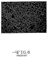
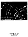
- Figs. 6 and 7 are photographs taken through an electron microscope at 500x and 5,000x, respectively, showing the surface condition of a ruthenium oxide coating produced by pressurized air atomization spraying according to the prior art.
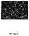
- Figs. 8 and 9 are photographs taken through an electron microscope at 500x and 5,000x, respectively, showing the surface condition of a ruthenium oxide coating produced from an ultrasonically generated aerosol/mist according to the present invention.
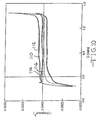
- Fig. 10 is a graph of the direct current capacitance of capacitors built according to the present invention in comparison to capacitors according to the prior art using the cyclic voltammetry technique.
- Fig. 1 illustrates a preferred ultrasonic aerosol deposition apparatus 10 according to the process of the present invention.
- the first step in the process includes providing a solution of reagents that are intended to be formed into an ultrasonically generated aerosol according to the present invention.
- the reagent solution is fed into or otherwise provided in a reagent chamber 12 via a feed line 14.
- the reagent solution preferably contains ions in substantially the ratio needed to form the desired coating from the ultrasonically generated aerosol. These ions are preferably available in solution in water soluble form such as in water soluble salts.
- salts including nitrates, sulfates and phosphates of the cations which are soluble in other solvents such as organic and inorganic solvents may be used.
- Water soluble salts include nitrates and chlorides.
- Other anions which form soluble salts with the cations also may be used.
- the reagent solution in the chamber 12 is moved through a conduit 16 to an ultrasonic nozzle 18.
- the reagent solution is caused to spray from the nozzle 18 in the form of an aerosol 20, such as a mist, by any conventional means which causes sufficient mechanical disturbance of the reagent solution.
- aerosol 20 refers to a suspension of ultramicroscopic solid or liquid particles in air or. gas having diameters of from about 0.1 microns to about 100 microns and preferably less than about 20 microns. Examples include smoke, fog and mist.
- mist refers to gas-suspended liquid particles having diameters less than about 20 microns.
- the aerosol/mist 20 is formed by ultrasonic means such as an ultrasonic generator (not shown) provided inside reagent chamber 12.
- the ultrasonic means contacts an exterior surface of the conduit 16 and the ultrasonic nozzle 18 assembly. Electrical power is provided to the ultrasonic generator through connector 22.
- ultrasonic sound waves are those having frequencies above 20,000 hertz.
- the ultrasonic power used to generate the aerosol/mist 20 is in excess of one-half of a watt and, more preferably, in excess of one watt.
- an ultrasonic generator useful with the present invention is manufactured by Sonotek of Milton, New York under model no. 8700-120MS.
- the oscillators (not shown) of the ultrasonic generator may contact an exterior surface of the reagent chamber 12 such as a diaphragm (not shown) so that the produced ultrasonic waves are transmitted via the diaphragm to effect misting of the reagent solution.
- the oscillators used to generate the aerosol/mist 20 are in direct contact with the reagent solution.
- the reagent chamber 12 may be any reaction container used by those skilled in the art and should preferably be constructed from such weak acid-resistant materials as titanium, stainless steel, glass, ceramic and plastic, and the like.
- the spray is contained by a shroud gas represented by arrows 24.
- the shroud gas 24 does not contact the reagent solution prior to atomization, but instead sprays from a plurality of shroud gas nozzles (not shown) supported by an air shroud chamber 26 serving as a manifold for the nozzles disposed in an annular array around the ultrasonic nozzle 18.
- the shroud gas 24 is introduced into the air shroud chamber 26 via feed line 28 and discharges from the shroud gas nozzles at a flow rate sufficient to screen and direct the aerosol/mist 20 toward a heated substrate 30 supported on a holder or a support block 32.
- the flow rate of the shroud gas 24 is from about 500 cc to about 25 liters per minute.
- the shroud gas 24 may comprise oxygen, air, argon, nitrogen, and the like. It is preferred that the shroud gas 24 be a compressed gas under a pressure in excess of 760 millimeters of mercury. Thus, the compressed shroud gas 24 facilitates the spraying of the aerosol/mist 20 from the ultrasonic nozzle 18 onto the substrate 30.
- Substrate 30 preferably consists of a conductive metal such as titanium, molybdenum, tantalum, niobium, cobalt, nickel, stainless steel, tungsten, platinum, palladium, gold, silver, copper, chromium, vanadium, aluminum, zirconium, hafnium, zinc and iron, and the like, and mixtures and alloys thereof.
- a conductive metal such as titanium, molybdenum, tantalum, niobium, cobalt, nickel, stainless steel, tungsten, platinum, palladium, gold, silver, copper, chromium, vanadium, aluminum, zirconium, hafnium, zinc and iron, and the like, and mixtures and alloys thereof.
- ultrasonically deposited spray coatings rely mostly upon mechanical bonding to the substrate surface. It is, therefore, critical that the substrate surface to be coated is properly prepared to ensure coating quality. For one, substrate surface cleanliness is very important in all coating systems, especially in ultrasonically deposited spray coatings. In that respect, it is required that the substrate surface remain uncontaminated by lubricants from handling equipment or body oils from hands and the like. Substrate cleaning includes chemical means such as conventional degreasing treatments using aqueous and nonaqueous solutions as well known to those skilled in the art. Plasma cleaning is also contemplated by the scope of the present invention.
- the substrate 30 may be roughened by chemical means, for example, by contacting the substrate with hydrofluoric acid and/or hydrochloric acid containing ammonium bromide and methanol and the like, by plasma etching, and by mechanical means such as scraping, machining, wire brushing, rough threading, grit blasting, a combination of rough threading then grit blasting and abrading such as by contacting the substrate with scotch-BriteTM abrasive sheets manufactured by 3M.
- the electrical conductivity of substrate is improved prior to coating.
- Metal and metal alloys have a native oxide present on their surface. This is a lows resistive layer and hence, if the material is to be used as a substrate for a capacitor electrode, the oxide is preferably removed or made electrically conductive prior to deposition of a pseudocapacitive coating thereon.
- various techniques can be employed. One is shown and described in U.S. Patent No. 5, 0 98,485 to Evans.
- a preferred method for improving the conductivity of the substrate includes depositing a minor amount of a metal or metals from Groups IA, IVA and VIIIA of the Periodic Table of Elements onto the substrate. Aluminum, manganese, nickel and copper are also suitable for this purpose.
- the deposited metal is then "intermixed" with the substrate material by, for example, a high energy ion beam or a laser beam directed towards the deposited surface.
- These substrate treating processes are performed at relatively low temperatures to prevent substrate degradation and deformation. Additionally, these treating processes can be used to passivate the substrate from further chemical reaction while still providing adequate electrical conductivity.
- the reagent solution preferably contains ions in substantially the stoichiometric ratio needed to form the desired coating.
- the ions are present in the reagent solution in a water-soluble form as water-soluble salts.
- Suitable water-soluble salts include nitrates and chlorides of the cations.
- salts such as sulfates and phosphates soluble in organic and inorganic solvents other than water may be used. Some of these other solvents include isopropyl alcohol and nitric acid and the like, and mixtures thereof.
- the aerosol/mist contacted substrate 30 consists essentially of a porous film coating (not shown) including the oxide of a first metal, or a precursor thereof, the nitride of the first metal, or a precursor thereof, the carbon nitride of the first metal, or a precursor thereof, and/or the carbide of the first metal, or a precursor thereof, the oxide, nitride, carbon nitride and carbide of the first metal having pseudocapacitive properties.
- the first metal is preferably selected from- .
- the deposited mixture can include a nitrate or a chloride of the metal.
- the porous coating may also include a second or more metals.
- the second metal is in the form of an oxide, a nitride, a carbon nitride or a carbide, or precursors thereof and is not essential to the intended use of the coated foil as a capacitor electrode and the like.
- the second metal is different than the first metal and is selected from one or more of-tantalum, titanium, nickel, iridium, platinum, palladium, gold, silver, cobalt, molybdenum, ruthenium, manganese, tungsten, iron, zirconium, hafnium, rhodium, vanadium, osmium, and niobium.
- the porous coating product includes oxides of ruthenium and tantalum.
- the metals intended to comprise the coating are present in solution in the desired stoichiometry, it does not matter whether they are present in the form of a salt, an oxide, or in another form.
- the solution contains either the salts of the coating metals, or their oxides.
- the reagent solution is preferably at a concentration of from about 0.01 to about 1,000 grams of the reagent compounds per liter of the reagent solution. In one embodiment of the present invention, it is preferred that the reagent solution has a concentration of from about 1 to about 300 grams per liter and, more preferably, from about 5 to about 40 grams per liter.
- the support block 32 for substrate 30 is heated via a power cable 34.
- the reagent solution contains a pseudocapacitive metal compound and during the ultrasonic spray deposition of the aerosol/mist 20 onto the substrate 30, support block 32 maintains the substrate 30 at a temperature sufficient to instantaneously evaporate or otherwise drive off the solvent from the deposited reagent mixture.
- the deposited film coating is comprised of a precursor of the pseudocapacitive metal compound
- the support block 32 maintains the substrate 30 at a temperature sufficient to instantaneously convert the precursor to a porous, high surface area metal oxide, metal nitride, metal carbon nitride or metal carbide coating on the substrate 30, as the case may be.
- the substrate 30 is being coated with the pseudocapacitive metal solution, or precursor thereof, the substrate is at a temperature sufficient to drive off or otherwise evaporate the solvent material to provide a solid, anhydrous form of the pseudocapacitive metal compound on the substrate.
- the solvent is instantaneously evaporated from the aerosol/mist 20 with contact to the substrate resulting in the deposition of a relatively thin film coating of an oxide of the first metal.
- the heated substrate also instantaneously converts the precursor to the final product in accordance to the present invention.
- the deposited nitrate or chloride mixture is instantaneously heated by contact with the substrate provided at a temperature sufficient to convert the deposited precursor to a highly porous, high surface area pseudocapacitive film. More particularly, as the oxide precursor aerosol/mist 20 is spraying onto the heated substrate 30, the substrate is at a temperature of about 100°C to about 500°C, preferably about 350°C to instantaneously convert the precursor to an oxide coating. After deposition and conversion to the pseudocapacitive compound, the substrate may be ramped down or cooled to ambient temperature, maintained at the heated deposition temperature, or varied according to a specific profile. In general, it is preferred to conduct this heating while contacting the substrate with air or an oxygen-containing gas.
- the ultrasonically generated aerosol is sprayed onto the substrate maintained at a temperature sufficient to evaporate or otherwise drive off the solvent from the deposited reagent mixture.
- the deposited film coating is comprised of a precursor of the pseudocapacitive melted compound, the coated substrate is then subjected to a separate heating step to convert the precursor to the final product.
- the porous coating has an internal surface area of about 10 m 2 /gram to about 1,500 m 2 /gram.
- the thickness of substrate 30 is typically in the range of about 0.001 millimeters to about 2 millimeter and preferably about 0.1 millimeters.
- temperature sensing means are used to sense the temperature of the substrate 30 and to adjust the power supplied to the support block 32 to regulate the substrate temperature as previously described.
- the substrate 30 may be of substantially any size or shape, and it may be stationary or movable. Because of the speed of the coating process, the substrate 30 may be moved across the spray emitting from nozzle 18 to have any or all of its surface coated with the film.
- the substrate 30 is preferably moved in a plane which is substantially normal to the direction of flow of the aerosol region 20. In another embodiment, the substrate 30 is moved stepwise along a predetermined path to coat the substrate only at certain predetermined areas.
- rotary substrate motion is utilized to expose the-surface of a complex-shaped article to the aerosol coating. This rotary substrate motion may be effected by conventional means.
- the process of the present invention provides for coating the substrate 30 at a deposition rate of from about 0.01 to about 10 microns per minute and, preferably, from about 0.1 to about 1.0 microns per minute.
- the thickness of the film coated upon the substrate 30 may be determined by means well known to those skilled in the art.
- the present aerosol spray deposition process provides a substantial amount of flexibility in varying the porosity and morphology of the deposited film.
- concentration of the reagent solution a higher concentration of the metal constituents produces a larger particle size as well as a higher deposition rate
- temperature of the substrate the higher the substrate temperature, the larger the size of the grains deposited
- energy supplied by the ultrasonic generator the greater the energy, the faster the deposition rate
- ultrasonic frequency the higher the frequency, the smaller the particle size resulting in a higher surface area aerosol deposited film
- the porosity and morphology of the deposited film coated onto the substrate 30 is controlled.
- the temperature of the substrate affects the crystal structure and coating adhesion strength.
- the generation of the aerosol/mist 20 and its deposition onto the substrate 30 is conducted under substantially atmospheric pressure conditions.
- substantially atmospheric refers to a pressure of at least about 600 millimeters of mercury and, preferably, from about 600 to about 1,000 millimeters of mercury. It is preferred that the aerosol generation occurs at about atmospheric pressure.
- atmospheric pressure at sea level is 760 millimeters of mercury.
- An ultrasonically coated substrate according to the present invention is useful as an electrode in various types of electrochemical capacitors including unipolar and bipolar designs, and capacitors having a spirally wound configuration.
- Fig. 2 there is shown a schematic representation of a typical unipolar electrochemical capacitor 40 having spaced apart electrodes 42 and 44.
- One of the electrodes, for example, electrode 42 serves as the cathode electrode and comprises an ultrasonically generated aerosol coating 46A of pseudocapacitive material provided on a conductive plate 48A according to the present invention.
- a porous ruthenium oxide film is provided on plate 48A which is of a conductive material such as tantalum.
- the relative thicknesses of the plate 48A and the pseudocapacitive coating 46A thereon are distorted for illustrative purposes.
- the plate is about 0.01 millimeters to about 1 millimeter in thickness and the pseudocapacitive coating 46A is in the range from a few hundred Angstroms to about 0.1 millimeters thick.
- the pseudocapacitive coating 46A is preferably in the range about 100 Angstroms to about 0.1 millimeters thick.
- the thickness of the pseudocapacitive coating 46A is in the range from about 150 Angstroms to about 0.1 millimeters. More preferably, the thickness of the pseudocapacitive coating 46A is in the range of about 200 Angstroms to about 0.1 millimeters.
- the other electrode 44 serves as the anode and is of a similar pseudocapacitive material 46B contacted to a conductive substrate 48B, as in electrode 42 separated from each other by an ion permeable membrane 50 serving as a separator.
- the electrodes 42 and 44 are maintained in the spaced apart relationship shown by opposed insulating members 52 and 54 such as of an elastomeric material contacting end portions of the plates 48A, 48B.
- the end plate portions typically are not coated with a pseudocapacitive material.
- An electrolyte (not shown), which may be any of the conventional electrolytes used in electrolytic capacitors, such as a solution of sulfuric acid, potassium hydroxide, or an ammonium salt is provided between and in contact with the cathode and anode electrodes 42 and 44.
- Electrodes are easily attached to the electrodes 42 and 44 before, during, or after assembly of the capacitor and the thusly constructed unipolar capacitor configuration is housed in a suitable casing, or the conductive plates along with the insulating member can serve as the capacitor housing.
- Fig. 3 is a schematic representation of a typical bipolar electrochemical capacitor 60 comprising a plurality of capacitor units 62 arranged and interconnected serially.
- Each unit 62 includes bipolar conductive substrate 64.
- Porous pseudocapacitive coating 66 and 68 are provided on the opposite sides of substrate 64 according to the present ultrasonic coating process. For example, a porous coating of ruthenium oxide film is deposited from an ultrasonically generated aerosol onto both sides of substrate 64. Again, the thickness of the porous coatings 66 and 68 is distorted for illustrative purposes.
- the units 62 are then assembled into the bipolar capacitor configuration on opposite sides of an intermediate separator 70. Elastomeric insulating members 72 and 74 are provided to maintain the units 62 in their spaced apart relationship.
- insulators 72, 74 Materials other than elastomeric materials may be apparent to those skilled in the art for use as insulators 72, 74.
- insulators 72, 74 Materials other than elastomeric materials may be apparent to those skilled in the art for use as insulators 72, 74.
- a plurality of individual electrochemical capacitor units 62 are interconnected in series to provide the bipolar configuration.
- the serial arrangement of units 62 is completed at the terminal ends thereof by end plates (not shown), as is well known to those skilled in the art.
- an electrolyte 74 is provided between and in contact with the coatings 66, 68 of the capacitor 60.
- Fig. 4 shows a schematic representation of an electrolytic capacitor 80 having spaced apart cathode electrode 82, 84, each comprising a respective ultrasonically generated aerosol coating 82A, 84A of pseudocapacitive material provided on a conductive plate 82B, 84B according to the present invention.
- the counter electrode or anode 86 is intermediate the cathodes 82, 84 with separators 88, 90 preventing contact between the electrodes.
- the anode 86 is of a conventional sintered, metal, preferably in a porous form.
- Suitable anode metals are selected from the group consisting of titanium, aluminum, niobium, zirconium, hafnium, tungsten, molybdenum, vanadium, silicon, germanium and tantalum contacted to a terminal pin 92.
- the hybrid capacitor 80 is completed by insulating members 94, 96 contacting end portions of the cathode plates. While not shown, an electrolyte is provided to activate the electrodes 82, 84 and 86.
- FIG. 5 is a schematic drawing of another embodiment of a jelly roll configured capacitor 100, which can be manufactured by the ultrasonic coating process according to the present invention.
- Capacitor 100 has a plurality of capacitor units 102, each comprising a conductive substrate provided with ultrasonically generated pseudocapacitive coatings 104, 106 on the opposed sides thereof.
- the coatings can be, for example, of ruthenium oxide, separated from immediately adjacent cells by an intermediate separator 108.
- This structure is then wound in a jelly roll fashion and housed in a suitable casing. Leads are contacted to the anode and cathode electrodes and the capacitor is activated by.an electrolyte in the customary manner.
- a precursor solution was prepared by dissolving 2.72 grams of ruthenium nitrosyl nitrate in a solvent that consisted of 100 cc of deionized water. If needed, a minor amount, i.e. about 5 cc of nitric acid is used to completely solubilize the precursor. The solution was stirred until the ruthenium nitrosyl nitrate was completely dissolved.
- a Becton-Dickinson, 30 cc. syringe was filled with the precursor solution and installed in the syringe pump. The pump was set to an injection flow rate of 2 cc/minute. The ruthenium precursor solution was then ready to be sprayed using the ultrasonic aerosol generator (Sonotek).
- the substrate was cleaned with appropriate cleaning solutions and mounted on the temperature controlled substrate holder.
- the substrate was a tantalum foil, 50.8 ⁇ m (0.002") thick.
- the foil was heated to a temperature of 350°C.
- the ultrasonic nozzle was positioned above the substrate at a height of 7cm.
- the power to the nozzle was set to 1.0W.
- the liquid precursor As the liquid precursor was pumped through the nozzle it was atomized into tiny droplets. The droplets were deposited on the heated substrate where the solvent evaporated and a ruthenium nitrosyl nitrate film was created on the surface of the foil.
- the foil temperature of 350°C was sufficient to convert the ruthenium nitrosyl nitrate to ruthenium oxide as the aerosol was being deposited.
- the film was allowed to remain on the heater block for half an hour in order to ensure that all the nitrate had been converted to the oxide.
- the droplet size in the aerosol/mist is smaller than that produced by the various prior art techniques previously discussed. This results in greater control over the manufacturing process in terms of controlling the coating morphology from one production run to the next. Also, there is less overspraying with the present process in comparison to pressurized air atomization spraying and the like. Furthermore, the use of an ultrasonically generated aerosol deposited on a conductive substrate to form an electrode for a capacitor according to the present invention provides a higher surface area coating than that obtainable by the prior art, and thus a higher capacitance electrode.
- Figs. 6 and 7 are photographs taken through an electron microscope at 500x and 5,000x, respectively, showing the surface condition of a ruthenium oxide coating produced by dipping according to the prior art.
- Figs. 8 and 9 are photographs taken through an electron microscope at 500x and 5,000x, respectively, showing the surface condition of a ruthenium oxide coating produced from an ultrasonically generated aerosol/mist according to the present invention.
- the film morphology of the present coatings is different than that of the prior art coating.
- the prior art coatings have a "cracked mud” appearance while the present coatings have the same "cracked mud” appearance plus additional structures on the "cracked mud” area.
- the cracks of the present coatings are also higher in density and thus they have an increased surface area.
- Fig. 10 is a graph of the current versus voltage of various capacitors built according to the present invention and built according to the prior art.
- the present invention capacitors contained electrodes made according to Example I.
- the prior art capacitors contained electrodes made by high pressure air atomization or nebulization of a ruthenium chloride solution that was subsequently heated to form a ruthenium oxide coating.
- curves 110 and 112 where constructed from the cyclic voltammetry scans of the respective present invention capacitors while curves 114 and 116 were constructed from the cyclic voltammetry scans of the two prior art capacitors.
- the scan rate was 10 mV/sec.
- the capacitance obtained from a capacitor having an electrode made according to the present invention is in the range of about 50 to 900 Farad/gram (F/g.) of coating material as measured by the cyclic voltammetry technique.
- the prior art capacitors used to construct curves 114 and 116 in Fig. 10 had capacitances of about 75 F/g. measured by the same technique.
Landscapes
- Engineering & Computer Science (AREA)
- Power Engineering (AREA)
- Microelectronics & Electronic Packaging (AREA)
- Electric Double-Layer Capacitors Or The Like (AREA)
- Other Surface Treatments For Metallic Materials (AREA)
- Fixed Capacitors And Capacitor Manufacturing Machines (AREA)
- Special Spraying Apparatus (AREA)
- Application Of Or Painting With Fluid Materials (AREA)
- Laminated Bodies (AREA)
- Chemical Treatment Of Metals (AREA)
Claims (33)
- Verfahren zur Bereitstellung eines Substrats (30), umfassend darauf bereitgestellt eine Beschichtung aus mindestens einer ersten pseudokapazitiven Metallverbindung, welches Verfahren die Schritte umfasst:a) Bereitstellen einer Lösung, umfassend entweder eine erste, pseudokapazitive Metallverbindung oder einen Vorläufer davon, worin die erste, pseudokapazitive Metallverbindung ein Oxid, ein Nitrit, ein Carbonitrid, ein Carbid oder eine Mischung davon von einem oder mehreren von Ruthenium, Molybdän, Wolfram, Tantal, Cobalt, Mangan, Nickel, Iridium, Eisen, Titan, Zirkonium, Hafnium, Rhodium, Vanadium, Osmium, Palladium, Platin oder Niob ist;b) Erwärmen des Substrats (30) auf eine erhöhte Temperatur;c) Unterwerfen der Lösung unter Ultraschallwellen, wodurch die Lösung zur Bildung eines Aerosols (20) veranlasst wird, undd) In-Kontakt-Bringen des Aerosols (20) mit einer Oberfläche des erwärmten Substrats (30), wobei das Substrat sich bei einer solchen Temperatur befindet, dass die erste, pseudokapazitive Metallverbindung sofort verfestigt wird oder der Vorläufer sofort zur verfestigten pseudokapazitiven Metallverbindung umgewandelt wird, dadurch Ausbilden einer Beschichtung aus Teilchen der pseudokapazitiven Metallverbindung auf der Substratoberfläche, worin eine Mehrheit der Teilchen einen Durchmesser von kleiner als 10 µm aufweist.
- Verfahren nach Anspruch 1, worin die Oberfläche, die mit dem Aerosol (20) in Kontakt gebracht werden soll, vor dem Beschichten vergrößert wurde.
- Verfahren gemäß Anspruch 2, worin die vergrößerte Oberfläche durch Kontaktieren des Substrats (30) mit einer Säure gebildet wird.
- Verfahren gemäß Anspruch 3, worin die Säure ausgewählt ist unter Fluorwasserstoffsäure und Salzsäure.
- Verfahren gemäß Anspruch 3, worin die Säure eine Säurelösung darstellt, umfassend Ammoniumbromid und Methanol.
- Verfahren nach Anspruch 2, worin die vergrößerte Oberfläche durch mechanische Mittel gebildet wird, umfassend rohes Gewindeschneiden, Sandstrahlen, Abschaben, Plasmaätzen, Abtragen und Drahtbürsten des Substrats.
- Verfahren nach einem der Ansprüche 1 bis 6, worin die Oberfläche des Substrats (30) hinsichtlich der elektrischen Leitfähigkeit gesteigert wurde.
- Verfahren nach einem der Ansprüche 1 bis 7, worin das Aerosol (20) durch Unterwerfen der Lösung unter Ultraschallwellen mit einer Frequenz von etwa 20.000 Hz und darüber gebildet worden ist.
- Verfahren nach einem der Ansprüche 1 bis 8, worin das Aerosol (20) durch Unterwerfen der Lösung unter Ultraschallwellen bei im Wesentlichen atmosphärischem Druck von mindestens etwa 600 mm Quecksilber gebildet worden ist.
- Verfahren nach einem der Ansprüche 1 bis 9, umfassend das Lösen des ersten Metalls in einem organischen oder anorganischen Lösungsmittel zur Bildung der Lösung.
- Verfahren nach einem der Ansprüche 1 bis 10, worin die Beschichtung aus dem Aerosol (20) des Vorläufers des ersten Metalls gebildet worden ist, das mit dem auf eine Temperatur von mindestens 100°C erwärmten Substrat (30) in Kontakt gebracht wurde.
- Verfahren nach einem der Ansprüche 1 bis 11, worin die poröse Beschichtung durch Abscheiden des mit Ultraschall erzeugten Aerosols (20) des Vorläufers der ersten pseudokapazitiven Metallverbindung auf dem erwärmten Substrat (30) in Luft oder einer Sauerstoff enthaltenden Atmosphäre gebildet wird.
- Substrat (30), herstellbar über ein Verfahren nach einem der Ansprüche 1 bis 12, worin das Substrat bereitgestellt darauf umfasst eine Beschichtung aus Teilchen mindestens einer ersten, pseudokapazitiven Metallverbindung, worin die erste pseudokapazitive Metallverbindung ein Oxid, Nitrid, Carbonitrid, Carbid oder eine Mischung davon von einem oder mehreren von Ruthenium, Molybdän, Wolfram, Tantal, Cobalt, Mangan, Nickel, Iridium, Eisen, Titan, Zirkonium, Hafnium, Rhodium, Vanadium, Osmium, Palladium, Platin oder Niob ist, worin die Beschichtung eine Mehrzahl ihrer Teilchen mit Durchmessern von kleiner als 10 µm aufweist.
- Substrat nach Anspruch 13, worin die Beschichtung ein zweites Metall umfasst.
- Substrat nach Anspruch 14, worin das zweite Metall ausgewählt ist unter Tantal, Titan, Nickel, Iridium, Platin, Palladium, Gold, Silber, Cobalt, Molybdän, Niob, Ruthenium, Mangan, Wolfram, Eisen, Zirkonium, Hafnium, Rhodium, Vanadium, Osmium und Mischungen davon.
- Substrat nach Anspruch 14 oder Anspruch 15, worin die Beschichtung aus Ruthenium und Tantal besteht.
- Substrat nach einem der Ansprüche 13 bis 16, worin eine innere Oberfläche der Beschichtung von 10 m2/g bis 1.500 m2/g ist.
- Substrat nach einem der Ansprüche 13 bis 17, worin die Beschichtung eine Dicke von 10-8 m bis 10-4 m aufweist.
- Substrat nach einem der Ansprüche 13 bis 18, worin das Substrat ein leitendes Metall ist.
- Substrat nach Anspruch 19, worin das leitende Metall Tantal, Titan, Nickel, Molybdän, Niob, Cobalt, Edelstahl, Wolfram, Platin, Palladium, Gold, Silber, Kupfer, Chrom, Vanadium, Aluminium, Zirkonium, Hafnium, Zink, Eisen oder eine Mischung davon ist.
- Substrat nach einem der Ansprüche 13 bis 20, worin das Substrat eine Dicke von 10-6 m bis 2 x 10⁻³ m aufweist.
- Substrat nach einem der Ansprüche 13 bis 21, worin die Beschichtung porös ist.
- Kondensator, umfassend:a) ein Gehäuse;b) eine Kathode, umfassend ein Substrat nach einem der Ansprüche 13 bis 22; oder ausgebildet über das Verfahren nach einem der Ansprüche 1 bis 12;c) eine Anode, beabstandet von der Kathodenbeschichtung; undd) einen Elektrolyten in Kontakt mit der Kathodenbeschichtung und der Anode, das Gehäuse enthaltend die Anode, die Kathode und den Elektrolyten.
- Kondensator nach Anspruch 23, worin das Gehäuse ein Metall umfasst und worin die Kathodenbeschichtung direkt auf einer Innenoberfläche des Gehäuses angeordnet ist.
- Kondensator nach Anspruch 23 oder Anspruch 24, worin die poröse Beschichtung eine Mischung von mindestens einem Oxid von Ruthenium, Molybdän, Wolfram, Tantal, Cobalt, Mangan, Eisen, Iridium, Nickel, Titan, Zirkonium, Hafnium, Rhodium, Vanadium, Osmium, Palladium, Platin und Niob und mindestens einem Oxid von Tantal, Titan, Nickel, Iridium, Platin, Palladium, Gold, Silber, Cobalt, Molybdän, Niob, Ruthenium, Mangan, Wolfram, Eisen, Zirkonium, Hafnium, Rhodium, Vanadium und Osmium umfasst.
- Kondensator nach Anspruch 25, worin die poröse Beschichtung eine Mischung von Oxiden von Ruthenium und Tantal umfasst.
- Kondensator nach einem der Ansprüche 23 bis 26, worin die Anode ausgewählt ist unter Tantal, Aluminium, Niob, Zirkonium, Titan, Hafnium, Wolfram, Molybdän, Vanadium, Silizium, Germanium oder Mischungen davon.
- Kondensator nach einem der Ansprüche 23 bis 26, worin die Anode aus einer pseudokapazitiven Metallverbindung besteht.
- Kondensator nach einem der Ansprüche 23 bis 28 als elektrochemischer Kondensator.
- Kondensator nach einem der Ansprüche 23 bis 28 als elektrolytischer Kondensator.
- Kondensator nach Anspruch 29 oder 30 mit einer unipolaren Konfiguration.
- Kondensator nach Anspruch 29 oder 30 mit einer bipolaren Konfiguration.
- Kondensator nach Anspruch 31 oder 32 mit einer spiralförmig aufgewickelten Konfiguration.
Applications Claiming Priority (2)
| Application Number | Priority Date | Filing Date | Title |
|---|---|---|---|
| US847219 | 1997-05-01 | ||
| US08/847,219 US5920455A (en) | 1997-05-01 | 1997-05-01 | One step ultrasonically coated substrate for use in a capacitor |
Publications (2)
| Publication Number | Publication Date |
|---|---|
| EP0877401A1 EP0877401A1 (de) | 1998-11-11 |
| EP0877401B1 true EP0877401B1 (de) | 2005-03-09 |
Family
ID=25300100
Family Applications (1)
| Application Number | Title | Priority Date | Filing Date |
|---|---|---|---|
| EP19980303434 Expired - Lifetime EP0877401B1 (de) | 1997-05-01 | 1998-05-01 | In einem Schritt Ultraschall-beschichtetes Substrat zur Verwendung in einem Kondensator |
Country Status (5)
| Country | Link |
|---|---|
| US (3) | US5920455A (de) |
| EP (1) | EP0877401B1 (de) |
| JP (1) | JPH10312931A (de) |
| AU (1) | AU730206B2 (de) |
| DE (1) | DE69829241D1 (de) |
Cited By (1)
| Publication number | Priority date | Publication date | Assignee | Title |
|---|---|---|---|---|
| CN108855680A (zh) * | 2018-07-23 | 2018-11-23 | 江苏大学 | 一种电极自动喷涂装置 |
Families Citing this family (88)
| Publication number | Priority date | Publication date | Assignee | Title |
|---|---|---|---|---|
| US20010024700A1 (en) * | 1997-05-01 | 2001-09-27 | Asbish Shah | Ruthenium-containing ultrasonically coated substrate for use in a capacitor and method of manufacture |
| US20030068509A1 (en) * | 1997-05-01 | 2003-04-10 | Ashish Shah | Ruthenium-containing oxide ultrasonically coated substrate for use in a capacitor and method of manufacture |
| US20030070920A1 (en) * | 1997-05-01 | 2003-04-17 | Ashish Shah | Electrode for use in a capacitor |
| US6208502B1 (en) * | 1998-07-06 | 2001-03-27 | Aerovox, Inc. | Non-symmetric capacitor |
| US6222723B1 (en) * | 1998-12-07 | 2001-04-24 | Joint Stock Company “Elton” | Asymmetric electrochemical capacitor and method of making |
| US8107223B2 (en) * | 1999-06-11 | 2012-01-31 | U.S. Nanocorp, Inc. | Asymmetric electrochemical supercapacitor and method of manufacture thereof |
| US7576971B2 (en) * | 1999-06-11 | 2009-08-18 | U.S. Nanocorp, Inc. | Asymmetric electrochemical supercapacitor and method of manufacture thereof |
| US6627252B1 (en) | 2000-05-12 | 2003-09-30 | Maxwell Electronic Components, Inc. | Electrochemical double layer capacitor having carbon powder electrodes |
| US6631074B2 (en) | 2000-05-12 | 2003-10-07 | Maxwell Technologies, Inc. | Electrochemical double layer capacitor having carbon powder electrodes |
| US7744957B2 (en) * | 2003-10-23 | 2010-06-29 | The Trustees Of Princeton University | Method and apparatus for depositing material |
| US8535759B2 (en) * | 2001-09-04 | 2013-09-17 | The Trustees Of Princeton University | Method and apparatus for depositing material using a dynamic pressure |
| US6643119B2 (en) | 2001-11-02 | 2003-11-04 | Maxwell Technologies, Inc. | Electrochemical double layer capacitor having carbon powder electrodes |
| US6813139B2 (en) * | 2001-11-02 | 2004-11-02 | Maxwell Technologies, Inc. | Electrochemical double layer capacitor having carbon powder electrodes |
| US7005214B2 (en) * | 2001-11-02 | 2006-02-28 | Wilson Greatbatch Technologies, Inc. | Noble metals coated on titanium current collectors for use in nonaqueous Li/CFx cells |
| KR100418931B1 (ko) * | 2001-12-19 | 2004-02-14 | 주식회사 하이닉스반도체 | 전극 물질 형성 방법 |
| CA2453328A1 (en) * | 2002-12-16 | 2004-06-16 | Wilson Greatbatch Technologies, Inc. | Dual anode capacitor interconnect design |
| US6899919B2 (en) * | 2003-01-21 | 2005-05-31 | Jack Chen | Method of making a high surface area electrode |
| US20040158291A1 (en) * | 2003-02-07 | 2004-08-12 | Polkinghorne Jeannette C. | Implantable heart monitors having electrolytic capacitors with hydrogen-getting materials |
| US6788523B1 (en) * | 2003-05-30 | 2004-09-07 | Kemet Electronics | Electrolyte for electrolytic capacitor |
| US7791860B2 (en) | 2003-07-09 | 2010-09-07 | Maxwell Technologies, Inc. | Particle based electrodes and methods of making same |
| US7352558B2 (en) | 2003-07-09 | 2008-04-01 | Maxwell Technologies, Inc. | Dry particle based capacitor and methods of making same |
| US7116547B2 (en) * | 2003-08-18 | 2006-10-03 | Wilson Greatbatch Technologies, Inc. | Use of pad printing in the manufacture of capacitors |
| US20060154416A1 (en) * | 2003-08-18 | 2006-07-13 | Seitz Keith W | Method of pad printing in the manufacture of capacitors |
| US7920371B2 (en) | 2003-09-12 | 2011-04-05 | Maxwell Technologies, Inc. | Electrical energy storage devices with separator between electrodes and methods for fabricating the devices |
| US7687102B2 (en) * | 2003-10-23 | 2010-03-30 | Medtronic, Inc. | Methods and apparatus for producing carbon cathodes |
| US6967829B2 (en) * | 2004-01-28 | 2005-11-22 | Greatbatch, Inc. | Capacitor interconnect design |
| US7038901B2 (en) * | 2004-02-13 | 2006-05-02 | Wilson Greatbatch Technologies, Inc. | Silicate additives for capacitor working electrolytes |
| US7090946B2 (en) | 2004-02-19 | 2006-08-15 | Maxwell Technologies, Inc. | Composite electrode and method for fabricating same |
| US7085126B2 (en) * | 2004-03-01 | 2006-08-01 | Wilson Greatbatch Technologies, Inc. | Molded polymeric cradle for containing an anode in an electrolytic capacitor from high shock and vibration conditions |
| US7012799B2 (en) * | 2004-04-19 | 2006-03-14 | Wilson Greatbatch Technologies, Inc. | Flat back case for an electrolytic capacitor |
| US7952853B2 (en) | 2004-04-27 | 2011-05-31 | Medtronic, Inc. | Capacitor electrolyte |
| US7715174B1 (en) | 2004-05-17 | 2010-05-11 | Pacesetter, Inc. | Electrolytic capacitors with alternate cathode materials for use in pulse discharge applications |
| US20100148128A1 (en) * | 2005-01-18 | 2010-06-17 | Ashish Shah | Pad printing of cathode active materials for incorporation into electrochemical cells |
| US7410509B2 (en) * | 2005-01-19 | 2008-08-12 | Greatbatch Ltd. | Sputtered ruthenium oxide coatings in electrolytic capacitor |
| US8155754B2 (en) * | 2005-01-25 | 2012-04-10 | Medtronic, Inc. | Method for fabrication of low-polarization implantable stimulation electrode |
| US7440258B2 (en) | 2005-03-14 | 2008-10-21 | Maxwell Technologies, Inc. | Thermal interconnects for coupling energy storage devices |
| US20060228495A1 (en) * | 2005-04-12 | 2006-10-12 | Robert Bosch Gmbh | Method of manufacturing an exhaust gas sensor |
| US7099143B1 (en) | 2005-05-24 | 2006-08-29 | Avx Corporation | Wet electrolytic capacitors |
| US8644003B2 (en) * | 2005-06-09 | 2014-02-04 | National University Corporation, Tokyo University Of Agriculture And Technology | Electrolytic capacitor element and process for producing the same |
| US9548166B2 (en) | 2005-06-30 | 2017-01-17 | Medtronic, Inc. | Capacitor electrolyte |
| US7092242B1 (en) | 2005-09-08 | 2006-08-15 | Greatbatch, Inc. | Polymeric restraints for containing an anode in an electrolytic capacitor from high shock and vibration conditions |
| JP2007095716A (ja) * | 2005-09-27 | 2007-04-12 | Sumitomo Electric Ind Ltd | 複合体およびそれを備えた半導体製造装置用サセプタ並びにパワーモジュール |
| US20070185242A1 (en) * | 2005-11-08 | 2007-08-09 | Yuhong Huang | Low temperature curing ink for printing oxide coating and process the same |
| US20090110810A1 (en) * | 2005-11-08 | 2009-04-30 | Chemat Technology, Inc. | Low temperature curing ink for printing oxide coating and process the same |
| US8229570B2 (en) * | 2006-01-30 | 2012-07-24 | Medtronic, Inc. | Implantable electrodes having zirconium nitride coatings |
| US7480130B2 (en) * | 2006-03-09 | 2009-01-20 | Avx Corporation | Wet electrolytic capacitor |
| US7511943B2 (en) * | 2006-03-09 | 2009-03-31 | Avx Corporation | Wet electrolytic capacitor containing a cathode coating |
| US7959711B2 (en) * | 2006-11-08 | 2011-06-14 | Shell Oil Company | Gas separation membrane system and method of making thereof using nanoscale metal material |
| US7483260B2 (en) | 2006-12-22 | 2009-01-27 | Greatbatch Ltd. | Dual anode capacitor with internally connected anodes |
| US8996129B2 (en) * | 2007-01-31 | 2015-03-31 | Medtronic, Inc. | Medical electrode including an iridium oxide surface and methods of fabrication |
| US20080232032A1 (en) | 2007-03-20 | 2008-09-25 | Avx Corporation | Anode for use in electrolytic capacitors |
| US7554792B2 (en) * | 2007-03-20 | 2009-06-30 | Avx Corporation | Cathode coating for a wet electrolytic capacitor |
| US7460356B2 (en) | 2007-03-20 | 2008-12-02 | Avx Corporation | Neutral electrolyte for a wet electrolytic capacitor |
| US7649730B2 (en) * | 2007-03-20 | 2010-01-19 | Avx Corporation | Wet electrolytic capacitor containing a plurality of thin powder-formed anodes |
| US7972866B2 (en) * | 2007-06-18 | 2011-07-05 | Nipro Diagnostics, Inc. | Biosensor and ultrasonic method of making a biosensor |
| US7983022B2 (en) | 2008-03-05 | 2011-07-19 | Greatbatch Ltd. | Electrically connecting multiple cathodes in a case negative multi-anode capacitor |
| US8023250B2 (en) * | 2008-09-12 | 2011-09-20 | Avx Corporation | Substrate for use in wet capacitors |
| JP5315156B2 (ja) * | 2008-09-19 | 2013-10-16 | 日東電工株式会社 | センサ基板の製造方法 |
| US8279585B2 (en) * | 2008-12-09 | 2012-10-02 | Avx Corporation | Cathode for use in a wet capacitor |
| US8345406B2 (en) * | 2009-03-23 | 2013-01-01 | Avx Corporation | Electric double layer capacitor |
| US8405956B2 (en) | 2009-06-01 | 2013-03-26 | Avx Corporation | High voltage electrolytic capacitors |
| US8223473B2 (en) * | 2009-03-23 | 2012-07-17 | Avx Corporation | Electrolytic capacitor containing a liquid electrolyte |
| US20110120974A1 (en) * | 2009-11-25 | 2011-05-26 | Chih-Hao Huang | Method For Atomizing A Surface Of A Substrate |
| US8551660B2 (en) * | 2009-11-30 | 2013-10-08 | Tai-Her Yang | Reserve power supply with electrode plates joined to auxiliary conductors |
| US8605411B2 (en) * | 2010-09-16 | 2013-12-10 | Avx Corporation | Abrasive blasted conductive polymer cathode for use in a wet electrolytic capacitor |
| US8514547B2 (en) | 2010-11-01 | 2013-08-20 | Avx Corporation | Volumetrically efficient wet electrolytic capacitor |
| US8259435B2 (en) | 2010-11-01 | 2012-09-04 | Avx Corporation | Hermetically sealed wet electrolytic capacitor |
| WO2012158162A1 (en) * | 2011-05-17 | 2012-11-22 | Empire Technology Development Llc | Graphene integrated energy storage devices having capacitive-like properties |
| US9105401B2 (en) | 2011-12-02 | 2015-08-11 | Avx Corporation | Wet electrolytic capacitor containing a gelled working electrolyte |
| US9129747B2 (en) | 2012-03-16 | 2015-09-08 | Avx Corporation | Abrasive blasted cathode of a wet electrolytic capacitor |
| US9312075B1 (en) | 2013-09-06 | 2016-04-12 | Greatbatch Ltd. | High voltage tantalum anode and method of manufacture |
| US9633796B2 (en) | 2013-09-06 | 2017-04-25 | Greatbatch Ltd. | High voltage tantalum anode and method of manufacture |
| USRE48439E1 (en) | 2013-09-06 | 2021-02-16 | Greatbatch Ltd. | High voltage tantalum anode and method of manufacture |
| US9875855B2 (en) | 2015-10-30 | 2018-01-23 | Greatbatch Ltd. | High voltage tantalum capacitor with improved cathode/separator design and method of manufacture |
| US20170125178A1 (en) | 2015-10-30 | 2017-05-04 | Greatbatch Ltd. | High voltage dual anode tantalum capacitor with facing casing clamshells contacting an intermediate partition |
| EP3171378B1 (de) | 2015-11-20 | 2021-12-22 | Greatbatch Ltd. | Hochspannungskondensator mit dualer tantalanoden/kathoden-stromabnehmerelektrodenanordnung, die in einer konstruktion mit zwei separatorhüllen untergebracht ist |
| CN105788889A (zh) * | 2016-04-26 | 2016-07-20 | 铜陵市新洲电子科技有限责任公司 | 一种新型电容器表面处理方法 |
| CN109715320A (zh) | 2016-08-12 | 2019-05-03 | 复合材料技术公司 | 电解电容器和改进电解电容器阳极的方法 |
| KR20190077321A (ko) | 2016-09-01 | 2019-07-03 | 컴포짓 매터리얼스 테크놀로지, 아이엔씨. | LIB 애노드용 밸브 금속 기판상의 나노-스케일/나노 구조화된 Si 코팅 |
| US9721730B1 (en) | 2017-03-03 | 2017-08-01 | Greatbatch Ltd. | Capacitor having multiple anodes housed in a stacked casing |
| US11195665B2 (en) | 2018-03-02 | 2021-12-07 | Greatbatch Ltd. | Titanium clad nickel termination-pad welded to a titanium tab for a capacitor |
| JP7209494B2 (ja) * | 2018-08-24 | 2023-01-20 | 株式会社Screenホールディングス | 基板処理装置、処理液および基板処理方法 |
| EP3863034A3 (de) | 2020-01-17 | 2021-10-27 | Greatbatch Ltd. | Segmentierte konforme anode für einen kondensator |
| US12119186B2 (en) | 2020-04-03 | 2024-10-15 | Greatbatch Ltd. | Electrolytic capacitor having an anode formed from a tantalum powder with a relatively low specific charge |
| US11450486B2 (en) | 2020-04-03 | 2022-09-20 | Greatbatch Ltd. | Electrolytic capacitor having a tantalum anode |
| US11462363B2 (en) | 2020-12-29 | 2022-10-04 | Greatbatch Ltd. | Electrolytic capacitor having a shaped anode wire that prevents failure due to a cracked anode |
| US12512274B2 (en) | 2022-08-26 | 2025-12-30 | KYOCERA AVX Components Corporation | Wet electrolytic capacitor containing a gelled working electrolyte |
| US20260001806A1 (en) * | 2024-07-01 | 2026-01-01 | Nippon Sheet Glass Company, Limited | Method for manufacturing glass plate including functional layer and functional layer forming device |
Citations (1)
| Publication number | Priority date | Publication date | Assignee | Title |
|---|---|---|---|---|
| US5369547A (en) * | 1993-03-22 | 1994-11-29 | The Evans Findings Co., Ltd. | Capacitor |
Family Cites Families (21)
| Publication number | Priority date | Publication date | Assignee | Title |
|---|---|---|---|---|
| US47A (en) * | 1836-10-11 | Oonead kile | ||
| BE526755A (de) * | 1953-02-24 | 1900-01-01 | ||
| GB1195871A (en) * | 1967-02-10 | 1970-06-24 | Chemnor Ag | Improvements in or relating to the Manufacture of Electrodes. |
| US3710474A (en) * | 1970-05-22 | 1973-01-16 | Fansteel Inc | Vanadium-modified tantalum foil |
| FR2110622A5 (de) * | 1970-10-23 | 1972-06-02 | Commissariat Energie Atomique | |
| US4242374A (en) * | 1979-04-19 | 1980-12-30 | Exxon Research & Engineering Co. | Process for thin film deposition of metal and mixed metal chalcogenides displaying semi-conductor properties |
| FR2543165B1 (fr) * | 1983-03-21 | 1987-08-14 | Commissariat Energie Atomique | Procede et dispositif d'elaboration de couches composites, par superposition, en continu et en atmosphere controlee |
| US4523255A (en) * | 1983-09-19 | 1985-06-11 | Sprague Electric Company | Cathode for an electrolytic capacitor |
| JPH0280303A (ja) * | 1987-06-04 | 1990-03-20 | Tonen Corp | 超伝導体薄膜の形成方法及びその為の装置 |
| JPH0713656B2 (ja) | 1988-09-09 | 1995-02-15 | 横河電機株式会社 | 多チャンネルスクイッド磁束計 |
| US5278138A (en) * | 1990-04-16 | 1994-01-11 | Ott Kevin C | Aerosol chemical vapor deposition of metal oxide films |
| US5260105A (en) * | 1990-04-17 | 1993-11-09 | Alfred University | Aerosol-plasma deposition of films for electrochemical cells |
| US5157015A (en) * | 1990-04-17 | 1992-10-20 | Alfred University | Process for preparing superconducting films by radio-frequency generated aerosol-plasma deposition in atmosphere |
| US5366770A (en) * | 1990-04-17 | 1994-11-22 | Xingwu Wang | Aerosol-plasma deposition of films for electronic cells |
| US5098485A (en) * | 1990-09-19 | 1992-03-24 | Evans Findings Company | Method of making electrically insulating metallic oxides electrically conductive |
| JP2935932B2 (ja) * | 1992-09-08 | 1999-08-16 | 住軽アルミ箔株式会社 | 電解コンデンサ用アルミニウム電極箔の製造方法 |
| US5464453A (en) * | 1992-09-18 | 1995-11-07 | Pinnacle Research Institute, Inc. | Method to fabricate a reliable electrical storage device and the device thereof |
| US5711988A (en) * | 1992-09-18 | 1998-01-27 | Pinnacle Research Institute, Inc. | Energy storage device and its methods of manufacture |
| US5384685A (en) * | 1992-09-18 | 1995-01-24 | Pinnacle Research Institute, Inc. | Screen printing of microprotrusions for use as a space separator in an electrical storage device |
| US5469325A (en) * | 1993-03-22 | 1995-11-21 | Evans Findings Co. | Capacitor |
| US5600535A (en) * | 1994-12-09 | 1997-02-04 | The United States Of America As Represented By The Secretary Of The Army | Amorphous thin film electrode materials from hydrous metal oxides |
-
1997
- 1997-05-01 US US08/847,219 patent/US5920455A/en not_active Expired - Lifetime
-
1998
- 1998-04-22 JP JP12951398A patent/JPH10312931A/ja active Pending
- 1998-04-29 AU AU63819/98A patent/AU730206B2/en not_active Ceased
- 1998-05-01 DE DE69829241T patent/DE69829241D1/de not_active Expired - Lifetime
- 1998-05-01 EP EP19980303434 patent/EP0877401B1/de not_active Expired - Lifetime
-
1999
- 1999-05-04 US US09/304,706 patent/US6224985B1/en not_active Expired - Lifetime
-
2001
- 2001-03-14 US US09/808,582 patent/US6468605B2/en not_active Expired - Lifetime
Patent Citations (1)
| Publication number | Priority date | Publication date | Assignee | Title |
|---|---|---|---|---|
| US5369547A (en) * | 1993-03-22 | 1994-11-29 | The Evans Findings Co., Ltd. | Capacitor |
Cited By (2)
| Publication number | Priority date | Publication date | Assignee | Title |
|---|---|---|---|---|
| CN108855680A (zh) * | 2018-07-23 | 2018-11-23 | 江苏大学 | 一种电极自动喷涂装置 |
| CN108855680B (zh) * | 2018-07-23 | 2021-03-23 | 江苏大学 | 一种电极自动喷涂装置 |
Also Published As
| Publication number | Publication date |
|---|---|
| US20010021411A1 (en) | 2001-09-13 |
| AU6381998A (en) | 1998-11-05 |
| AU730206B2 (en) | 2001-03-01 |
| US6468605B2 (en) | 2002-10-22 |
| DE69829241D1 (de) | 2005-04-14 |
| US6224985B1 (en) | 2001-05-01 |
| US5920455A (en) | 1999-07-06 |
| EP0877401A1 (de) | 1998-11-11 |
| JPH10312931A (ja) | 1998-11-24 |
Similar Documents
| Publication | Publication Date | Title |
|---|---|---|
| EP0877401B1 (de) | In einem Schritt Ultraschall-beschichtetes Substrat zur Verwendung in einem Kondensator | |
| US5894403A (en) | Ultrasonically coated substrate for use in a capacitor | |
| US6455108B1 (en) | Method for preparation of a thermal spray coated substrate for use in an electrical energy storage device | |
| EP1508907B1 (de) | Druckverfahren zur Herstellung einer Kondensatorelektrode | |
| US8213159B2 (en) | Electrode foil, method of manufacturing electrode foil, and electrolytic capacitor | |
| CN1910711B (zh) | 双电层电容器、其制造方法和使用其的电子装置 | |
| US20080013257A1 (en) | Poly(Alkylene) Carbonates As Binders In The Manufacture Of Valve Metal Anodes For Electrolytic Capacitors | |
| US5600535A (en) | Amorphous thin film electrode materials from hydrous metal oxides | |
| EP0953197A1 (de) | Metallnitride und metalloxynitride mit hoher spezifischer oberfläche zum speichern von elektrischer energie | |
| US4184192A (en) | Solid electrolyte compacitor using low resistivity metal oxide as cathode collector | |
| US20080007894A1 (en) | Poly (Alkylene) Carbonates As Binders In The Manufacture Of Valve Metal Anodes For Electrolytic Capacitors | |
| US3375413A (en) | Electrolytic capacitor comprising filmforming metal sheet carrying a dielectric oxide film and a metal dioxide electrolyte layer | |
| US20010026850A1 (en) | Method for providing a coated substrate for use in a capacitor by a one step ultrasonic deposition process | |
| US7410509B2 (en) | Sputtered ruthenium oxide coatings in electrolytic capacitor | |
| US20030070920A1 (en) | Electrode for use in a capacitor | |
| US20010024700A1 (en) | Ruthenium-containing ultrasonically coated substrate for use in a capacitor and method of manufacture | |
| US20060154416A1 (en) | Method of pad printing in the manufacture of capacitors | |
| US20030068509A1 (en) | Ruthenium-containing oxide ultrasonically coated substrate for use in a capacitor and method of manufacture | |
| WO1998014970A1 (en) | High surface area metal nitrides or metal oxynitrides for electrical energy storage | |
| US20100014271A1 (en) | Capacitor material, production method of the same, and capacitor, wiring board and electronic device containing that material | |
| JPH0547609A (ja) | 電解コンデンサ用電極箔の製造方法 | |
| JPH08203783A (ja) | 固体電解コンデンサ及びその製造方法 | |
| JPS6134250B2 (de) | ||
| JPH0713936B2 (ja) | 固体電解コンデンサの製造方法 |
Legal Events
| Date | Code | Title | Description |
|---|---|---|---|
| PUAI | Public reference made under article 153(3) epc to a published international application that has entered the european phase |
Free format text: ORIGINAL CODE: 0009012 |
|
| AK | Designated contracting states |
Kind code of ref document: A1 Designated state(s): DE FR GB IT NL SE |
|
| AX | Request for extension of the european patent |
Free format text: AL;LT;LV;MK;RO;SI |
|
| 17P | Request for examination filed |
Effective date: 19981023 |
|
| AKX | Designation fees paid |
Free format text: DE FR GB IT NL SE |
|
| 17Q | First examination report despatched |
Effective date: 20000117 |
|
| GRAP | Despatch of communication of intention to grant a patent |
Free format text: ORIGINAL CODE: EPIDOSNIGR1 |
|
| GRAS | Grant fee paid |
Free format text: ORIGINAL CODE: EPIDOSNIGR3 |
|
| GRAA | (expected) grant |
Free format text: ORIGINAL CODE: 0009210 |
|
| AK | Designated contracting states |
Kind code of ref document: B1 Designated state(s): DE FR GB IT NL SE |
|
| PG25 | Lapsed in a contracting state [announced via postgrant information from national office to epo] |
Ref country code: NL Free format text: LAPSE BECAUSE OF FAILURE TO SUBMIT A TRANSLATION OF THE DESCRIPTION OR TO PAY THE FEE WITHIN THE PRESCRIBED TIME-LIMIT Effective date: 20050309 Ref country code: IT Free format text: LAPSE BECAUSE OF FAILURE TO SUBMIT A TRANSLATION OF THE DESCRIPTION OR TO PAY THE FEE WITHIN THE PRESCRIBED TIME-LIMIT;WARNING: LAPSES OF ITALIAN PATENTS WITH EFFECTIVE DATE BEFORE 2007 MAY HAVE OCCURRED AT ANY TIME BEFORE 2007. THE CORRECT EFFECTIVE DATE MAY BE DIFFERENT FROM THE ONE RECORDED. Effective date: 20050309 |
|
| REG | Reference to a national code |
Ref country code: GB Ref legal event code: FG4D |
|
| REF | Corresponds to: |
Ref document number: 69829241 Country of ref document: DE Date of ref document: 20050414 Kind code of ref document: P |
|
| PG25 | Lapsed in a contracting state [announced via postgrant information from national office to epo] |
Ref country code: GB Free format text: LAPSE BECAUSE OF NON-PAYMENT OF DUE FEES Effective date: 20050609 |
|
| PG25 | Lapsed in a contracting state [announced via postgrant information from national office to epo] |
Ref country code: DE Free format text: LAPSE BECAUSE OF FAILURE TO SUBMIT A TRANSLATION OF THE DESCRIPTION OR TO PAY THE FEE WITHIN THE PRESCRIBED TIME-LIMIT Effective date: 20050610 |
|
| NLV1 | Nl: lapsed or annulled due to failure to fulfill the requirements of art. 29p and 29m of the patents act | ||
| PLBE | No opposition filed within time limit |
Free format text: ORIGINAL CODE: 0009261 |
|
| STAA | Information on the status of an ep patent application or granted ep patent |
Free format text: STATUS: NO OPPOSITION FILED WITHIN TIME LIMIT |
|
| 26N | No opposition filed |
Effective date: 20051212 |
|
| GBPC | Gb: european patent ceased through non-payment of renewal fee |
Effective date: 20050609 |
|
| EN | Fr: translation not filed | ||
| PG25 | Lapsed in a contracting state [announced via postgrant information from national office to epo] |
Ref country code: SE Free format text: LAPSE BECAUSE OF FAILURE TO SUBMIT A TRANSLATION OF THE DESCRIPTION OR TO PAY THE FEE WITHIN THE PRESCRIBED TIME-LIMIT Effective date: 20050609 |
|
| PG25 | Lapsed in a contracting state [announced via postgrant information from national office to epo] |
Ref country code: FR Free format text: LAPSE BECAUSE OF NON-PAYMENT OF DUE FEES Effective date: 20050531 |
|
| PG25 | Lapsed in a contracting state [announced via postgrant information from national office to epo] |
Ref country code: FR Free format text: LAPSE BECAUSE OF NON-PAYMENT OF DUE FEES Effective date: 20050309 |