EP0877228B1 - Magnetoresistiver Sensor für Dimensionsbestimmung - Google Patents
Magnetoresistiver Sensor für Dimensionsbestimmung Download PDFInfo
- Publication number
- EP0877228B1 EP0877228B1 EP97810290A EP97810290A EP0877228B1 EP 0877228 B1 EP0877228 B1 EP 0877228B1 EP 97810290 A EP97810290 A EP 97810290A EP 97810290 A EP97810290 A EP 97810290A EP 0877228 B1 EP0877228 B1 EP 0877228B1
- Authority
- EP
- European Patent Office
- Prior art keywords
- magneto
- electrodes
- measuring device
- resistive electrodes
- groups
- Prior art date
- Legal status (The legal status is an assumption and is not a legal conclusion. Google has not performed a legal analysis and makes no representation as to the accuracy of the status listed.)
- Expired - Lifetime
Links
Images


Classifications
-
- G—PHYSICS
- G01—MEASURING; TESTING
- G01R—MEASURING ELECTRIC VARIABLES; MEASURING MAGNETIC VARIABLES
- G01R33/00—Arrangements or instruments for measuring magnetic variables
- G01R33/02—Measuring direction or magnitude of magnetic fields or magnetic flux
- G01R33/06—Measuring direction or magnitude of magnetic fields or magnetic flux using galvano-magnetic devices
- G01R33/09—Magnetoresistive devices
- G01R33/093—Magnetoresistive devices using multilayer structures, e.g. giant magnetoresistance sensors
-
- B—PERFORMING OPERATIONS; TRANSPORTING
- B82—NANOTECHNOLOGY
- B82Y—SPECIFIC USES OR APPLICATIONS OF NANOSTRUCTURES; MEASUREMENT OR ANALYSIS OF NANOSTRUCTURES; MANUFACTURE OR TREATMENT OF NANOSTRUCTURES
- B82Y25/00—Nanomagnetism, e.g. magnetoimpedance, anisotropic magnetoresistance, giant magnetoresistance or tunneling magnetoresistance
-
- G—PHYSICS
- G01—MEASURING; TESTING
- G01R—MEASURING ELECTRIC VARIABLES; MEASURING MAGNETIC VARIABLES
- G01R33/00—Arrangements or instruments for measuring magnetic variables
- G01R33/02—Measuring direction or magnitude of magnetic fields or magnetic flux
- G01R33/06—Measuring direction or magnitude of magnetic fields or magnetic flux using galvano-magnetic devices
- G01R33/09—Magnetoresistive devices
- G01R33/096—Magnetoresistive devices anisotropic magnetoresistance sensors
Definitions
- the present invention relates to a dimension measurement device comprising a magnetoresistive type sensor according to the preamble of claim 1 . More specifically, the invention relates the arrangement of magnetoresistive electrodes in a type sensor magnetoresistive.
- Electronic devices for measuring length or position angular in an industrial environment for example must generally satisfy several partially contradictory constraints. They must provide sufficient accuracy and resolution, and be usable in environments subject to vibration or pollution such as dust, oil or moisture. These sensors are also expected to easy integration into low volume devices, without adjustments or important adaptations, high measurement speed and consumption as small as possible.
- measuring devices based on different physical principles, have been developed to meet these requirements variety.
- measurement systems using variations in capacity caused by the movement of a sensor next to a rule have been widely used in particular in portable devices such than calibers for example. These devices must be kept clean enough to function and are therefore unsuitable for operation in a humid environment or subject to splashes of lubricant or cut for example.
- Length measuring devices based on the principle of magnetoresistive electrodes have been proposed for example in the patent document DE4233331 (IMO), which offer good resistance superior to soiling.
- the device described in this document includes a sensor provided with a network of magnetoresistive electrodes connected so as to define two measurement bridges.
- the electrodes are arranged and connected so that all the tracks are in the same plane, i.e. that no crossroads are necessary.
- the sensor is mounted on a slide and can be moved in front of a magnetized ruler with a period of magnetization ⁇ .
- the magnetoresistive electrodes of the sensor are spread over a length equal to two periods of the rule.
- a displacement of the sensor facing the ruler causes a change in the magnetic field applied to the various magnetoresistive electrodes of the sensor, and therefore a modification of their resistance.
- an electrical signal which is a periodic function of the position is collected at their output of the sensor along the ruler.
- the two measuring bridges consist of four electrodes magnetoresistive phase shifted by ⁇ / 2.
- the corresponding electrodes of each bridge occupies positions shifted by ⁇ / 4.
- the electrodes of two bridges are intertwined.
- These conductive strips constitute equipotential lines; between the strips, the current takes the shortest path and therefore flows with an inclination of 45 ° relative to the axis of the electrodes magnetoresistive.
- This structure makes it possible to modify the direction of the vector current I.
- the barberpole structures allow to control the direction and amplitude of the variation in resistance of the electrodes caused by the displacement of the sensor.
- Each branch of the measuring bridge consists of a single magnetoresistive electrode whose width must be sufficient to react to relatively small magnetic fields generated by the rule.
- the resistance of the branches of the bridge is therefore reduced, and large currents flow through the measuring bridges. The power consumption of this device is therefore important.
- US Patent 4,845,456 A describes a magnetic displacement sensor comprising a bridge of measurement formed by magnetoresistive electrodes. Magnetoresistive electrodes are made by two or three parts arranged at a predetermined distance and connected by conductors of low resistivity.
- Patent DE 4233331A describes a magnetic displacement sensor comprising a bridge measurement formed by magnetoresistive electrodes carrying structures on their surface barberpoles formed by thin conductive strips regularly arranged at a constant angle to the length of the magnetoresistive electrodes
- An object of the invention is to provide a type sensor magnetoresistive for improved length and / or angle measuring device compared to the devices of the prior art.
- a goal of the present invention is to provide a magnetoresistive type sensor which enables high precision measurements with high sensitivity and low energy consumption.
- Another goal is to make a sensor magnetoresistive easily integrated into an existing measuring device.
- FIG. 1 schematically illustrates a portion of sensor 1 above a portion of rule 2.
- the rule includes a magnetization periodic in the horizontal direction x and -x.
- the magnetization period, or period of rule, is worth ⁇ , that is to say that the length of the segments 20, 21 magnetized in a determined direction is worth ⁇ / 2.
- Rule 2 is preferably fixed in relation to the whole of the measuring device, while the magnetoresistive sensor 1 can move at short distance above the ruler.
- the measuring device constitutes a measuring column or a caliper
- rule 2 is integral of the frame or the rule of the device, while the sensor 1 is associated with a slide that can slide along the frame or ruler.
- the length of the sensor is typically of the order of a few centimeters against several tens of centimeters for the ruler.
- Other provisions, in particular a inversion of the rule and the sensor are also possible.
- the ruler can be constituted by a network of electrodes on the periphery of an axis, and the sensor placed inside a cylindrical ring around this axis.
- the rule can for example be made by an aluminum strip on which is deposited a material with high magnetic coercivity (ferrites).
- the magnetic field H x (x) is a sinusoidal function of the position x, the approximation of the sine improving with increasing distance.
- FIG. 1 illustrates by arrows the direction of the magnetic field vector H (x) between the rule and the sensor.
- the cost of the device therefore represents a constraint for the distance a between the sensor and the rule.
- the magnetoresistive devices of the prior art were therefore reserved for expensive devices such as height measuring column, machine tool or optical microscope for example.
- the sensor of the invention can operate at a distance from the rule a of the order of 200 to 700 ⁇ m, preferably 500 ⁇ m, which allows use it in portable calipers.
- the sensor 1 is provided with magnetoresistive electrodes 100 (visible in particular in Figure 4).
- the magnetoresistive electrodes are provided with barberpole structures, i.e. thin parallel strips of material conductor inclined approximately + -45 ° relative to the axis of the electrodes.
- the half of the electrodes are fitted with barberpoles oriented at + 45 ° while the other half is equipped with barberpoles oriented at -45 °. It is possible to show that an identical magnetic field H produced on an electrode magnetoresistive with structure of barberpoles oriented at + 45 ° a resistance variation ⁇ r opposite to that produced on an electrode magnetoresistive with barberpole structure oriented at -45 °.
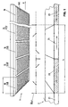
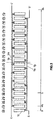
- the magnetoresistive electrodes 100 are distributed longitudinally on the sensor 1 so as to constitute x groups 10, in this example 24 consecutive electrode groups, of which only a few are illustrated in figure 1.
- the arrangement of the 24 groups of electrodes magnetoresistive is illustrated in Figure 3.
- Each group consists of y magnetoresistive electrodes 100 spread over a length w, in this example 24 electrodes spread over a length w equal to ⁇ / 4, i.e. 0.25 millimeters (see Figure 4).
- the phase shift between the signals received by two groups successive is 90 °.
- FIG. 2 illustrates the way in which the different magnetoresistive electrodes 100 on the sensor are connected so as to define two measurement bridges.
- Each measurement bridge has four branches, each branch consisting of a set of magnetoresistive electrodes A, B, C, D and A ', B', C ', D'.
- the two measurement bridges are supplied between voltages U P and U N.
- Each set of electrodes A, B, C, D, A ', B', C ', D' is constituted in this example by 72 electrodes connected in series.
- the magnetoresistive electrodes 100 have a length of approximately 1 millimeter and a width of the order of 5 ⁇ m, it is possible to obtain with current magnetoresistive materials a high resulting resistance, greater than 10 k ⁇ , preferably greater than 50 k ⁇ , for each set of magnetoresistive electrodes and therefore for each bridge.
- the currents flowing through the two measurement bridges are therefore very low, which makes it possible to limit the electrical consumption compared to the devices of the prior art and to supply the sensor on battery for example.
- the four ABCD games of the first ABCD deck come from in contrast of the 12 even groups, that is to say occupying positions along of the sensor equal to 0, ⁇ / 2, ⁇ , etc.
- the signal received at the CC 'output of the second bridge is therefore 90 ° out of phase with the signal received at the SS 'output of the first bridge.
- Each set of electrodes is constituted by a half-set of 36 magnetoresistive electrodes occupying first positions of the same phase and provided with barberpole structures oriented in a first direction, and by a second half-set of 36 other electrodes occupying phase-shifted positions 180 ° to the first positions and fitted with barberpole structures oriented in the second direction.
- the resistance variation caused by the magnetic field H x (x) on the two half-games is therefore the same for a given position x of the sensor.
- the set of electrodes B comes from the same groups as the set of electrodes A, the orientation of the barberpole structures being however opposite.
- Voltage dividers AB, CD and A'B ', C'D' of each measuring bridge are thus constituted by magnetoresistive electrodes from the same portion of the sensor; of the local variations in magnetization of the rule are thus compensated for the inside of the measuring bridges.
- Set C electrodes occupy 180 ° phase shift positions relative to the electrodes of set A and share the same orientation of barberpole structures.
- This arrangement is in particular visible in FIG. 3, in which two letters and two symbols / and ⁇ indicate the games above each group of electrodes which constitute it as well as the orientation of the barberpole structures chosen.
- the barberpole structures are also directly indicated on the electrodes of the group shown in FIG. 4.
- each magnetoresistive electrode is a function of the magnetic field H x (x) applied.
- H x (x) is an approximately sinusoidal function and therefore contains harmonics.
- the resistance R (x) of each magnetoresistive electrode 100 therefore varies approximately sinusoidally when the sensor 1 moves in the magnetic field generated by the rule 2.
- the resistance of each set of electrodes 100 in one of the bridges ABCD or A'B'C'D ' is equal to the sum of the resistance of the 72 electrodes in series which make up this set. These 72 electrodes are divided into 6 groups which occupy identical phase positions (or 180 ° phase shifted, but with opposite orientation of the barberpoles).
- each set of electrodes A to D ' is equal to the resistance of 12 magnetoresistive electrodes 100 spread over a width w around the position x (modulo ⁇ / 2), multiplied by six (six groups by Game).
- the resistance of a set of electrodes therefore takes account of the value of H x (x) between the positions [Xw / 2; X + w / 2].
- the increase in the number of electrodes per group can also result from the simultaneous increase in the spreading w of the groups and the pitch of rule ⁇ .
- the increase in ⁇ makes it possible to increase the value of the magnetic field H x at the level of the magnetoresistive electrodes, and therefore their sensitivity.
- the number y of electrodes per group is therefore voluntarily important, in any case greater than 8, in the example illustrated equal to 24.
- 8 sets of electrodes are necessary, which must come from 4 groups (at least).
- n 2 measuring bridges, so we will choose a number x of multiple groups of 4, for example 4, 8, 12, 16, 20, 24, 32, 36, 40 or 48. If you want to use half sets of electrodes, i.e. sets made up of electrodes with two opposite orientations of the structures of barberpole, we will limit our to values x multiple of 8.
- FIG. 4 illustrates by way of example a group 10 of electrodes magnetoresistive 100 from a first set A with barberpoles oriented at + 45 ° and a second set B with barberpoles oriented at -45 °.
- the succession chosen ABBAABBAABB .. etc .. allows on the one hand ensure that the center of gravity of the electrodes of two sets, here A and B, in the same group is superimposed, and on the other hand to connect all the electrodes between them on a single plane, without crossings.
- the electrodes A, respectively B, of this group are connected in series with the electrodes A, respectively B, of a group spaced from ⁇ / 2 and provided with barberpoles oriented at -45 °, respectively + 45 °. No bridge or crossing is only necessary to link groups 10 together.
- the number n of measuring bridges used can be different from 2; steps can also be made with a single measurement bridge, or with three phase-shifted bridges 120 ° for example.
- steps can also be made with a single measurement bridge, or with three phase-shifted bridges 120 ° for example.
- barberpole structures oriented with angles different from + -45 ° one great freedom can be gained to distribute the groups 10 on the sensor and the electrodes 100 inside the groups 10.
- the electrode groups can also consist of electrodes coming from one game, rather than two intertwined games.
Landscapes
- Physics & Mathematics (AREA)
- Condensed Matter Physics & Semiconductors (AREA)
- General Physics & Mathematics (AREA)
- Chemical & Material Sciences (AREA)
- Engineering & Computer Science (AREA)
- Nanotechnology (AREA)
- Crystallography & Structural Chemistry (AREA)
- Measuring Magnetic Variables (AREA)
- Transmission And Conversion Of Sensor Element Output (AREA)
- Measurement Of Length, Angles, Or The Like Using Electric Or Magnetic Means (AREA)
- Hall/Mr Elements (AREA)
Claims (19)
- Vorrichtung zur Messung von linearen oder winkligen Dimensionen, umfassend ein magnetisiertes Lineal (2), welches ein magnetisches Feld H(x) mit einer Periode λ generiert, und einen Sensor (1), welcher mit Bezug auf besagtem Lineal (2) bewegt werden kann und mit magnetoresistiven Elektroden (100) versehen ist, die zusammen verbunden sind, um mindestens zwei Messbrücken (ABCD; A'B'C'D') zu bilden, wobei jede Messbrücke aus vier Sätzen von magnetoresistiven Elektroden besteht, wobei die jeden Satz bildenden magnetoresistiven Elektroden seriell verbunden sind, dadurch gekennzeichnet, dass die jeden Satz bildenden magnetoresistiven Elektroden an verschiedenen Phasen in Bezug auf besagter Periode λ angeordnet werden, um harmonische Komponenten von besagtem magnetischen Feld H(x) zu filtrieren.
- Messvorrichtung gemäss dem vorhergehenden Anspruch, dadurch gekennzeichnet, dass die magnetoresistiven Elektroden jedes Satzes über eine Gesamtlänge gleich λ/4 verteilt sind.
- Messvorrichtung gemäss einem der Ansprüche 1 oder 2, dadurch gekennzeichnet, dass die magnetoresistiven Elektroden (100) längs verteilt sind, so dass sie x Gruppen (10) bilden, die je aus y aufeinander folgenden magnetoresistiven Elektroden aus maximal zwei Sätzen einer gleichen Messbrücke bestehen, wobei die Anzahl y von magnetoresistiven Elektroden (100) pro Gruppe grösser als acht ist.
- Messvorrichtung gemäss einem der vorhergehenden Ansprüche, dadurch gekennzeichnet, dass mindestens gewisse magnetoresistive Elektroden (100) Barberpole-Strukturen aufweisen.
- Messvorrichtung gemäss einem der vorhergehenden Ansprüche, dadurch gekennzeichnet, dass die magnetoresistiven Elektroden (100) besagter Gruppen (10) aus zwei Sätzen (AB; A'B'; CD; C'D') stammen, und dass die Schwerpunkte der beiden Sätzen von magnetoresistiven Elektroden in einer Gruppe (10) und deren Barberpole-Strukturen so gewählt werden, dass ein gleiches, aus dem Lineal 2 entstandenes magnetisches Feld eine entgegengesetzte Widerstandsvariation in den beiden Sätzen von magnetoresistiven Elektroden induziert.
- Messvorrichtung gemäss einem der vorhergehenden Ansprüche, dadurch gekennzeichnet, dass die Folge von magnetoresistiven Elektroden (100) beider Sätze (beispielsweise A und B) in jeder Gruppe (10) vom Typ ABBAABBAABB... ist.
- Messvorrichtung gemäss einem der vorhergehenden Ansprüche, dadurch gekennzeichnet, dass sie eine Anzahl n von Messbrücken umfasst, und dass die aufeinander folgenden Gruppen (10) um 180°/n phase-verschoben sind.
- Messvorrichtung gemäss einem der vorhergehenden Ansprüche, dadurch gekennzeichnet, dass jede Messbrücke (ABCD; A'B'C'D') aus vier Sätzen von magnetoresistiven Elektroden (100) besteht, welche aus um 180° phase-verschobenen Paaren von Gruppen (10) stammen.
- Messvorrichtung gemäss einem der vorhergehenden Ansprüche, dadurch gekennzeichnet, dass jeder Satz (A, B, C, D, A', B', C', D') magnetoresistive Elektroden umfasst, welche aus mindestens zwei Gruppen (10) gleicher Phase stammen.
- Messvorrichtung gemäss einem der Ansprüche 4 bis 9, dadurch gekennzeichnet, dass jeder Satz magnetoresistive Elektroden (100) umfasst, welche aus mindestens zwei Gruppen (10) stammen, die um 180° phase-verschoben sind und mit Barberpole-Strukturen entgegengesetzter Richtungen versehen sind.
- Messvorrichtung gemäss einem der vorhergehenden Ansprüche, dadurch gekennzeichnet, dass die Anzahl n von Messbrücken (ABCD; A'B'C'D') gleich zwei ist, und dass die Anzahl x von Gruppen (10) ein ganzzahliges Vielfaches von acht ist, und dass die magnetoresistiven Elektroden jedes Satzes aus mindestens zwei ersten Gruppen gleicher Phase und mit einer in einer ersten Richtung orientierten Barberpole-Struktur sowie aus mindestens zwei zweiten Gruppen, welche in Bezug auf besagter ersten Gruppe um 180° phase-verschoben sind und eine in einer zweiten Richtung orientierte Barberpole-Struktur aufweisen, stammen.
- Messvorrichtung gemäss einem der vorhergehenden Ansprüche, dadurch gekennzeichnet, dass jede Messbrücke (ABCD; A'B'C'D') aus vier Sätzen von magnetoresistiven Elektroden (100) besteht, wobei alle magnetoresistive Elektroden (100) der beiden Sätzen in der ersten Hälfte der Elektroden verteilt sind, während alle Elektroden der zwei anderen Sätzen in der zweiten Hälfte der Elektroden verteilt sind.
- Messvorrichtung gemäss einem der vorhergehenden Ansprüche, dadurch gekennzeichnet, dass die Anzahl x von Gruppen (10) gleich 24 ist.
- Messvorrichtung gemäss einem der vorhergehenden Ansprüche, dadurch gekennzeichnet, dass die Anzahl y von magnetoresistiven Elektroden (100) pro Gruppe (10) gleich 24 ist.
- Messvorrichtung gemäss einem der vorhergehenden Ansprüche, dadurch gekennzeichnet, dass die Periode λ im Intervall {0,5 mm-1,5 mm} enthalten ist.
- Messvorrichtung gemäss einem der vorhergehenden Ansprüche, dadurch gekennzeichnet, dass der resultierende Widerstand jedes Satzes (ABCD; A'B'C'D') von magnetoresistiven Elektroden grösser als 10 kΩ ist.
- Messvorrichtung gemäss einem der vorhergehenden Ansprüche, dadurch gekennzeichnet, dass die magnetoresistiven Elektroden über mindestens viermal die Länge der Periode λ. Verteilt sind.
- Messvorrichtung gemäss dem vorhergehenden Anspruch, dadurch gekennzeichnet, dass der Abstand zwischen dem Lineal und den magnetoresistiven Elektroden (100) im Intervall {200 µm-700 µm} enthalten ist.
- Messvorrichtung gemäss Anspruch 18, dadurch gekennzeichnet, dass sie Batteriegespeist ist.
Priority Applications (7)
| Application Number | Priority Date | Filing Date | Title |
|---|---|---|---|
| EP97810290A EP0877228B1 (de) | 1997-05-09 | 1997-05-09 | Magnetoresistiver Sensor für Dimensionsbestimmung |
| DE69723960T DE69723960T2 (de) | 1997-05-09 | 1997-05-09 | Magnetoresistiver Sensor für Dimensionsbestimmung |
| EP03100897A EP1329695B1 (de) | 1997-05-09 | 1997-05-09 | Magnetoresistiver Sensor für Dimensionsbestimmung |
| JP10140465A JP3089406B2 (ja) | 1997-05-09 | 1998-05-07 | 大きさ計測用磁気抵抗センサー及び大きさ計測装置 |
| US09/073,792 US6191578B1 (en) | 1997-05-09 | 1998-05-07 | Magnetoresistive sensor for high precision measurements of lengths and angles |
| CN98107990A CN1101542C (zh) | 1997-05-09 | 1998-05-08 | 测量尺度的磁阻传感器 |
| HK99100766A HK1015870A1 (en) | 1997-05-09 | 1999-02-25 | Magnetoresistive sensor for measuring dimension |
Applications Claiming Priority (1)
| Application Number | Priority Date | Filing Date | Title |
|---|---|---|---|
| EP97810290A EP0877228B1 (de) | 1997-05-09 | 1997-05-09 | Magnetoresistiver Sensor für Dimensionsbestimmung |
Related Child Applications (1)
| Application Number | Title | Priority Date | Filing Date |
|---|---|---|---|
| EP03100897A Division EP1329695B1 (de) | 1997-05-09 | 1997-05-09 | Magnetoresistiver Sensor für Dimensionsbestimmung |
Publications (2)
| Publication Number | Publication Date |
|---|---|
| EP0877228A1 EP0877228A1 (de) | 1998-11-11 |
| EP0877228B1 true EP0877228B1 (de) | 2003-08-06 |
Family
ID=8230228
Family Applications (2)
| Application Number | Title | Priority Date | Filing Date |
|---|---|---|---|
| EP03100897A Expired - Lifetime EP1329695B1 (de) | 1997-05-09 | 1997-05-09 | Magnetoresistiver Sensor für Dimensionsbestimmung |
| EP97810290A Expired - Lifetime EP0877228B1 (de) | 1997-05-09 | 1997-05-09 | Magnetoresistiver Sensor für Dimensionsbestimmung |
Family Applications Before (1)
| Application Number | Title | Priority Date | Filing Date |
|---|---|---|---|
| EP03100897A Expired - Lifetime EP1329695B1 (de) | 1997-05-09 | 1997-05-09 | Magnetoresistiver Sensor für Dimensionsbestimmung |
Country Status (6)
| Country | Link |
|---|---|
| US (1) | US6191578B1 (de) |
| EP (2) | EP1329695B1 (de) |
| JP (1) | JP3089406B2 (de) |
| CN (1) | CN1101542C (de) |
| DE (1) | DE69723960T2 (de) |
| HK (1) | HK1015870A1 (de) |
Families Citing this family (17)
| Publication number | Priority date | Publication date | Assignee | Title |
|---|---|---|---|---|
| EP1052473B1 (de) | 1997-12-22 | 2003-05-02 | Brown & Sharpe Tesa S.A. | Magnetische Messanordnungen mit reduziertem Energieverbrauch oder Stand By Modus |
| CN1237323C (zh) * | 2000-06-27 | 2006-01-18 | 特莎有限公司 | 具有磁阻电极的测量装置及其测量方法 |
| US6633462B2 (en) * | 2000-07-13 | 2003-10-14 | Koninklijke Philips Electronics N.V. | Magnetoresistive angle sensor having several sensing elements |
| DE10158053A1 (de) * | 2001-11-27 | 2003-06-05 | Philips Intellectual Property | Sensoranordnung |
| US6803760B2 (en) * | 2002-07-30 | 2004-10-12 | Comprehensive Power, Inc. | Apparatus and method for determining an angular position of a rotating component |
| US7005915B2 (en) * | 2004-02-27 | 2006-02-28 | Honeywell International Inc. | Series bridge circuit with amplifiers |
| CN100375890C (zh) * | 2005-09-09 | 2008-03-19 | 清华大学 | 含有可调零的gmr芯片的磁位移传感器 |
| JP4801447B2 (ja) * | 2006-01-13 | 2011-10-26 | 旭化成株式会社 | 磁気センサを用いた測定装置及び測定方法 |
| CN100489561C (zh) * | 2006-07-20 | 2009-05-20 | 上海交通大学 | 教学用地磁场测量实验装置 |
| EP2153165B1 (de) * | 2007-05-29 | 2012-06-20 | Nxp B.V. | Externe magnetfeldwinkelbestimmung |
| US7530177B1 (en) | 2007-11-08 | 2009-05-12 | Mitutoyo Corporation | Magnetic caliper with reference scale on edge |
| US7965077B2 (en) * | 2008-05-08 | 2011-06-21 | Everspin Technologies, Inc. | Two-axis magnetic field sensor with multiple pinning directions |
| US8525514B2 (en) * | 2010-03-19 | 2013-09-03 | Memsic, Inc. | Magnetometer |
| DE102013104486A1 (de) * | 2013-05-02 | 2014-11-20 | Sensitec Gmbh | Magnetfeldsensorvorrichtung |
| JP6605570B2 (ja) * | 2017-12-27 | 2019-11-13 | Tdk株式会社 | 磁気センサ |
| CN109752677A (zh) * | 2019-01-10 | 2019-05-14 | 东南大学 | 一种双电桥式薄膜磁阻传感器 |
| CN109752675A (zh) * | 2019-01-10 | 2019-05-14 | 东南大学 | 一种正八边形薄膜磁阻传感器 |
Family Cites Families (11)
| Publication number | Priority date | Publication date | Assignee | Title |
|---|---|---|---|---|
| JPS6045804B2 (ja) * | 1978-02-28 | 1985-10-12 | 日本電気株式会社 | 角度検出器 |
| JPS5979806A (ja) * | 1982-10-29 | 1984-05-09 | Hitachi Ltd | 多相磁気回転センサおよび多相−2相出力変換方法 |
| JPH077012B2 (ja) * | 1987-08-18 | 1995-01-30 | 富士通株式会社 | 加速度センサ |
| JPH01178816A (ja) * | 1988-01-11 | 1989-07-17 | Alps Electric Co Ltd | 磁気センサ |
| JPH02264818A (ja) * | 1989-04-05 | 1990-10-29 | Seiko Epson Corp | 磁気エンコーダー |
| JP2924236B2 (ja) * | 1991-03-20 | 1999-07-26 | ソニー・プレシジョン・テクノロジー株式会社 | 磁気センサおよび位置検出装置 |
| DE4203073C2 (de) * | 1992-02-04 | 1994-12-15 | Heidenhain Gmbh Dr Johannes | Positionsmeßeinrichtung |
| DE4233331C2 (de) * | 1992-10-05 | 1995-06-01 | Inst Mikrostrukturtechnologie | Anordnung zur Bestimmung von Positionen |
| DE4316221C2 (de) * | 1993-05-14 | 1995-11-23 | Heidenhain Gmbh Dr Johannes | Positionsmeßeinrichtung |
| DE4319146C2 (de) * | 1993-06-09 | 1999-02-04 | Inst Mikrostrukturtechnologie | Magnetfeldsensor, aufgebaut aus einer Ummagnetisierungsleitung und einem oder mehreren magnetoresistiven Widerständen |
| DE59600344D1 (de) * | 1996-01-13 | 1998-08-20 | Heidenhain Gmbh Dr Johannes | Magnetische Sensoranordnung |
-
1997
- 1997-05-09 DE DE69723960T patent/DE69723960T2/de not_active Expired - Lifetime
- 1997-05-09 EP EP03100897A patent/EP1329695B1/de not_active Expired - Lifetime
- 1997-05-09 EP EP97810290A patent/EP0877228B1/de not_active Expired - Lifetime
-
1998
- 1998-05-07 US US09/073,792 patent/US6191578B1/en not_active Expired - Lifetime
- 1998-05-07 JP JP10140465A patent/JP3089406B2/ja not_active Expired - Fee Related
- 1998-05-08 CN CN98107990A patent/CN1101542C/zh not_active Expired - Lifetime
-
1999
- 1999-02-25 HK HK99100766A patent/HK1015870A1/xx not_active IP Right Cessation
Also Published As
| Publication number | Publication date |
|---|---|
| JPH10332426A (ja) | 1998-12-18 |
| US6191578B1 (en) | 2001-02-20 |
| CN1101542C (zh) | 2003-02-12 |
| EP1329695A1 (de) | 2003-07-23 |
| EP0877228A1 (de) | 1998-11-11 |
| DE69723960D1 (de) | 2003-09-11 |
| EP1329695B1 (de) | 2005-10-05 |
| HK1015870A1 (en) | 1999-10-22 |
| JP3089406B2 (ja) | 2000-09-18 |
| CN1199856A (zh) | 1998-11-25 |
| DE69723960T2 (de) | 2004-07-22 |
Similar Documents
| Publication | Publication Date | Title |
|---|---|---|
| EP0877228B1 (de) | Magnetoresistiver Sensor für Dimensionsbestimmung | |
| EP0538184B1 (de) | Kapazitiver Positionsdetektor | |
| EP1052473B1 (de) | Magnetische Messanordnungen mit reduziertem Energieverbrauch oder Stand By Modus | |
| EP0785415B1 (de) | Induktiver Weggeber | |
| EP0648998B1 (de) | Instrument zum Messen der Längen oder Winkel | |
| EP2417443B1 (de) | Vorrichtung zur zerstörungsfreien überprüfung einer elektrisch leitenden struktur | |
| CA2973053C (fr) | Roulement comprenant un capteur de deplacement angulaire | |
| EP0558364B1 (de) | Magnetstruktur für einen Verschiebungssensor | |
| CA2973050C (fr) | Capteurs inductifs de deplacement | |
| FR2503609A1 (fr) | Detecteur de position pour cylindre de travail | |
| CA2973052A1 (fr) | Capteurs inductifs de deplacement | |
| CA2973055C (fr) | Capteurs inductifs de deplacement | |
| EP1017967A1 (de) | Digitaler geber zur messung einer relativen position | |
| EP0717265B1 (de) | Magnetischer Kodierer zum Lesen von Markierungen auf einer dazugehörigen magnetischen Spur | |
| EP1055132A1 (de) | Riesenmagnetowiederstandsmagnetfeldwandle | |
| EP3708963B1 (de) | System zur bestimmung mindestens eines parameters der rotation eines rotationsorgans | |
| EP3540377B1 (de) | System zur bestimmung mindestens eines parameters der drehung eines drehorgans | |
| FR2803030A1 (fr) | Capteur analogique de position sans contact | |
| EP3077833A1 (de) | Analogspektrumsanalysator | |
| WO2018069389A1 (fr) | Procédé de génération d'une pluralité de courants présentant chacun une fréquence | |
| FR3133444A1 (fr) | Capteur linéaire inductif | |
| WO2022200740A1 (fr) | Système de capteur pour la détermination d'une position angulaire relative, un procédé de fabrication d'un corps aimanté et une méthode mettant en œuvre un tel capteur | |
| FR2686993A1 (fr) | Dispositif compteur de tours comportant un micro-circuit a bulles magnetiques. | |
| FR2788344A1 (fr) | Dispositif de mesure d'un courant circulant dans un conducteur |
Legal Events
| Date | Code | Title | Description |
|---|---|---|---|
| PUAI | Public reference made under article 153(3) epc to a published international application that has entered the european phase |
Free format text: ORIGINAL CODE: 0009012 |
|
| AK | Designated contracting states |
Kind code of ref document: A1 Designated state(s): CH DE FR GB LI |
|
| AX | Request for extension of the european patent |
Free format text: AL;LT;LV;RO;SI |
|
| 17P | Request for examination filed |
Effective date: 19990201 |
|
| AKX | Designation fees paid |
Free format text: CH DE FR GB LI |
|
| 17Q | First examination report despatched |
Effective date: 20020729 |
|
| GRAH | Despatch of communication of intention to grant a patent |
Free format text: ORIGINAL CODE: EPIDOS IGRA |
|
| GRAH | Despatch of communication of intention to grant a patent |
Free format text: ORIGINAL CODE: EPIDOS IGRA |
|
| RAP1 | Party data changed (applicant data changed or rights of an application transferred) |
Owner name: TESA SA |
|
| GRAA | (expected) grant |
Free format text: ORIGINAL CODE: 0009210 |
|
| AK | Designated contracting states |
Designated state(s): CH DE FR GB LI |
|
| REG | Reference to a national code |
Ref country code: GB Ref legal event code: FG4D Free format text: NOT ENGLISH |
|
| REG | Reference to a national code |
Ref country code: CH Ref legal event code: EP |
|
| REF | Corresponds to: |
Ref document number: 69723960 Country of ref document: DE Date of ref document: 20030911 Kind code of ref document: P |
|
| REG | Reference to a national code |
Ref country code: CH Ref legal event code: NV Representative=s name: CHRISTOPHE SAAM PATENTS & TECHNOLOGY SURVEYS SA |
|
| GBT | Gb: translation of ep patent filed (gb section 77(6)(a)/1977) | ||
| PLBE | No opposition filed within time limit |
Free format text: ORIGINAL CODE: 0009261 |
|
| STAA | Information on the status of an ep patent application or granted ep patent |
Free format text: STATUS: NO OPPOSITION FILED WITHIN TIME LIMIT |
|
| 26N | No opposition filed |
Effective date: 20040507 |
|
| REG | Reference to a national code |
Ref country code: CH Ref legal event code: PCAR Free format text: PATENTS & TECHNOLOGY SURVEYS SA;RUE DES TERREAUX 7 CASE POSTALE 2848;2001 NEUCHATEL (CH) |
|
| REG | Reference to a national code |
Ref country code: CH Ref legal event code: PFA Owner name: TESA SA Free format text: TESA SA#RUE DU BUGNON 38#1020 RENENS (CH) -TRANSFER TO- TESA SA#RUE DU BUGNON 38#1020 RENENS (CH) |
|
| PGFP | Annual fee paid to national office [announced via postgrant information from national office to epo] |
Ref country code: FR Payment date: 20130603 Year of fee payment: 17 |
|
| PGFP | Annual fee paid to national office [announced via postgrant information from national office to epo] |
Ref country code: GB Payment date: 20140521 Year of fee payment: 18 |
|
| REG | Reference to a national code |
Ref country code: FR Ref legal event code: ST Effective date: 20150130 |
|
| PG25 | Lapsed in a contracting state [announced via postgrant information from national office to epo] |
Ref country code: FR Free format text: LAPSE BECAUSE OF NON-PAYMENT OF DUE FEES Effective date: 20140602 |
|
| GBPC | Gb: european patent ceased through non-payment of renewal fee |
Effective date: 20150509 |
|
| PG25 | Lapsed in a contracting state [announced via postgrant information from national office to epo] |
Ref country code: GB Free format text: LAPSE BECAUSE OF NON-PAYMENT OF DUE FEES Effective date: 20150509 |
|
| PGFP | Annual fee paid to national office [announced via postgrant information from national office to epo] |
Ref country code: DE Payment date: 20160520 Year of fee payment: 20 Ref country code: CH Payment date: 20160519 Year of fee payment: 20 |
|
| REG | Reference to a national code |
Ref country code: DE Ref legal event code: R071 Ref document number: 69723960 Country of ref document: DE |
|
| REG | Reference to a national code |
Ref country code: CH Ref legal event code: PL |