EP0876311B1 - Procede pour le traitement biologique de matieres organiques et dispositif pour la mise en oeuvre du procede - Google Patents
Procede pour le traitement biologique de matieres organiques et dispositif pour la mise en oeuvre du procede Download PDFInfo
- Publication number
- EP0876311B1 EP0876311B1 EP97901083A EP97901083A EP0876311B1 EP 0876311 B1 EP0876311 B1 EP 0876311B1 EP 97901083 A EP97901083 A EP 97901083A EP 97901083 A EP97901083 A EP 97901083A EP 0876311 B1 EP0876311 B1 EP 0876311B1
- Authority
- EP
- European Patent Office
- Prior art keywords
- reactor
- washing liquid
- agitator
- process according
- liquid
- Prior art date
- Legal status (The legal status is an assumption and is not a legal conclusion. Google has not performed a legal analysis and makes no representation as to the accuracy of the status listed.)
- Expired - Lifetime
Links
- 238000000034 method Methods 0.000 title claims abstract description 71
- 239000011368 organic material Substances 0.000 title description 8
- 239000000463 material Substances 0.000 claims abstract description 131
- 239000010815 organic waste Substances 0.000 claims abstract description 13
- 238000006731 degradation reaction Methods 0.000 claims abstract description 10
- 239000007788 liquid Substances 0.000 claims description 79
- 238000005406 washing Methods 0.000 claims description 33
- 238000011049 filling Methods 0.000 claims description 11
- 239000000126 substance Substances 0.000 claims description 11
- 230000015556 catabolic process Effects 0.000 claims description 10
- 239000000203 mixture Substances 0.000 claims description 10
- XLYOFNOQVPJJNP-UHFFFAOYSA-N water Substances O XLYOFNOQVPJJNP-UHFFFAOYSA-N 0.000 claims description 9
- 230000000694 effects Effects 0.000 claims description 8
- 238000011001 backwashing Methods 0.000 claims description 6
- 238000006243 chemical reaction Methods 0.000 claims description 6
- 238000004140 cleaning Methods 0.000 claims description 6
- 239000010802 sludge Substances 0.000 claims description 6
- 239000010796 biological waste Substances 0.000 claims description 5
- 235000014113 dietary fatty acids Nutrition 0.000 claims description 4
- 229930195729 fatty acid Natural products 0.000 claims description 4
- 239000000194 fatty acid Substances 0.000 claims description 4
- 150000004665 fatty acids Chemical class 0.000 claims description 4
- 238000007667 floating Methods 0.000 claims description 4
- 238000012545 processing Methods 0.000 claims description 4
- 230000008929 regeneration Effects 0.000 claims description 4
- 238000011069 regeneration method Methods 0.000 claims description 4
- 238000005507 spraying Methods 0.000 claims description 4
- 235000013305 food Nutrition 0.000 claims description 3
- 238000000926 separation method Methods 0.000 claims description 3
- 239000000356 contaminant Substances 0.000 claims description 2
- 230000002503 metabolic effect Effects 0.000 claims description 2
- 239000004033 plastic Substances 0.000 claims description 2
- 230000001105 regulatory effect Effects 0.000 claims description 2
- 239000004576 sand Substances 0.000 claims description 2
- VNWKTOKETHGBQD-UHFFFAOYSA-N methane Chemical compound C VNWKTOKETHGBQD-UHFFFAOYSA-N 0.000 claims 4
- 238000012216 screening Methods 0.000 claims 2
- 239000002910 solid waste Substances 0.000 claims 2
- 241000894006 Bacteria Species 0.000 claims 1
- 230000015572 biosynthetic process Effects 0.000 claims 1
- 238000001035 drying Methods 0.000 claims 1
- 230000002441 reversible effect Effects 0.000 claims 1
- 239000011343 solid material Substances 0.000 claims 1
- 238000010792 warming Methods 0.000 claims 1
- 239000007921 spray Substances 0.000 abstract description 8
- 238000005273 aeration Methods 0.000 abstract 1
- 238000000354 decomposition reaction Methods 0.000 description 10
- 239000002699 waste material Substances 0.000 description 10
- 238000003756 stirring Methods 0.000 description 9
- 244000005700 microbiome Species 0.000 description 7
- 238000002156 mixing Methods 0.000 description 6
- 238000011161 development Methods 0.000 description 3
- 230000018109 developmental process Effects 0.000 description 3
- 238000004064 recycling Methods 0.000 description 3
- 238000009423 ventilation Methods 0.000 description 3
- 239000002361 compost Substances 0.000 description 2
- 238000009264 composting Methods 0.000 description 2
- 230000029087 digestion Effects 0.000 description 2
- 238000010438 heat treatment Methods 0.000 description 2
- 230000007062 hydrolysis Effects 0.000 description 2
- 238000006460 hydrolysis reaction Methods 0.000 description 2
- 239000012535 impurity Substances 0.000 description 2
- 230000020477 pH reduction Effects 0.000 description 2
- 239000013049 sediment Substances 0.000 description 2
- 239000002028 Biomass Substances 0.000 description 1
- 206010010774 Constipation Diseases 0.000 description 1
- 238000006065 biodegradation reaction Methods 0.000 description 1
- 239000003795 chemical substances by application Substances 0.000 description 1
- 238000010276 construction Methods 0.000 description 1
- 238000011109 contamination Methods 0.000 description 1
- 238000010586 diagram Methods 0.000 description 1
- 238000004090 dissolution Methods 0.000 description 1
- 238000011143 downstream manufacturing Methods 0.000 description 1
- 230000009977 dual effect Effects 0.000 description 1
- 238000005516 engineering process Methods 0.000 description 1
- 230000007717 exclusion Effects 0.000 description 1
- 238000000855 fermentation Methods 0.000 description 1
- 239000012530 fluid Substances 0.000 description 1
- 238000011081 inoculation Methods 0.000 description 1
- 239000011147 inorganic material Substances 0.000 description 1
- 238000004519 manufacturing process Methods 0.000 description 1
- 238000005259 measurement Methods 0.000 description 1
- 230000002906 microbiologic effect Effects 0.000 description 1
- 239000005416 organic matter Substances 0.000 description 1
- 238000005192 partition Methods 0.000 description 1
- 239000002985 plastic film Substances 0.000 description 1
- 229920006255 plastic film Polymers 0.000 description 1
- 238000012958 reprocessing Methods 0.000 description 1
- 230000000630 rising effect Effects 0.000 description 1
- 150000003839 salts Chemical class 0.000 description 1
- 238000011012 sanitization Methods 0.000 description 1
- 230000003068 static effect Effects 0.000 description 1
- 230000005654 stationary process Effects 0.000 description 1
- 230000002123 temporal effect Effects 0.000 description 1
- 238000012549 training Methods 0.000 description 1
- 235000013311 vegetables Nutrition 0.000 description 1
- 238000009736 wetting Methods 0.000 description 1
Images
Classifications
-
- C—CHEMISTRY; METALLURGY
- C12—BIOCHEMISTRY; BEER; SPIRITS; WINE; VINEGAR; MICROBIOLOGY; ENZYMOLOGY; MUTATION OR GENETIC ENGINEERING
- C12P—FERMENTATION OR ENZYME-USING PROCESSES TO SYNTHESISE A DESIRED CHEMICAL COMPOUND OR COMPOSITION OR TO SEPARATE OPTICAL ISOMERS FROM A RACEMIC MIXTURE
- C12P5/00—Preparation of hydrocarbons or halogenated hydrocarbons
- C12P5/02—Preparation of hydrocarbons or halogenated hydrocarbons acyclic
- C12P5/023—Methane
-
- B—PERFORMING OPERATIONS; TRANSPORTING
- B01—PHYSICAL OR CHEMICAL PROCESSES OR APPARATUS IN GENERAL
- B01F—MIXING, e.g. DISSOLVING, EMULSIFYING OR DISPERSING
- B01F23/00—Mixing according to the phases to be mixed, e.g. dispersing or emulsifying
- B01F23/30—Mixing gases with solids
-
- B—PERFORMING OPERATIONS; TRANSPORTING
- B01—PHYSICAL OR CHEMICAL PROCESSES OR APPARATUS IN GENERAL
- B01F—MIXING, e.g. DISSOLVING, EMULSIFYING OR DISPERSING
- B01F27/00—Mixers with rotary stirring devices in fixed receptacles; Kneaders
- B01F27/60—Mixers with rotary stirring devices in fixed receptacles; Kneaders with stirrers rotating about a horizontal or inclined axis
- B01F27/62—Mixers with rotary stirring devices in fixed receptacles; Kneaders with stirrers rotating about a horizontal or inclined axis comprising liquid feeding, e.g. spraying means
-
- B—PERFORMING OPERATIONS; TRANSPORTING
- B09—DISPOSAL OF SOLID WASTE; RECLAMATION OF CONTAMINATED SOIL
- B09B—DISPOSAL OF SOLID WASTE
- B09B3/00—Destroying solid waste or transforming solid waste into something useful or harmless
-
- C—CHEMISTRY; METALLURGY
- C05—FERTILISERS; MANUFACTURE THEREOF
- C05F—ORGANIC FERTILISERS NOT COVERED BY SUBCLASSES C05B, C05C, e.g. FERTILISERS FROM WASTE OR REFUSE
- C05F17/00—Preparation of fertilisers characterised by biological or biochemical treatment steps, e.g. composting or fermentation
- C05F17/50—Treatments combining two or more different biological or biochemical treatments, e.g. anaerobic and aerobic treatment or vermicomposting and aerobic treatment
-
- C—CHEMISTRY; METALLURGY
- C05—FERTILISERS; MANUFACTURE THEREOF
- C05F—ORGANIC FERTILISERS NOT COVERED BY SUBCLASSES C05B, C05C, e.g. FERTILISERS FROM WASTE OR REFUSE
- C05F17/00—Preparation of fertilisers characterised by biological or biochemical treatment steps, e.g. composting or fermentation
- C05F17/90—Apparatus therefor
- C05F17/921—Devices in which the material is conveyed essentially horizontally between inlet and discharge means
- C05F17/939—Means for mixing or moving with predetermined or fixed paths, e.g. rails or cables
-
- C—CHEMISTRY; METALLURGY
- C05—FERTILISERS; MANUFACTURE THEREOF
- C05F—ORGANIC FERTILISERS NOT COVERED BY SUBCLASSES C05B, C05C, e.g. FERTILISERS FROM WASTE OR REFUSE
- C05F17/00—Preparation of fertilisers characterised by biological or biochemical treatment steps, e.g. composting or fermentation
- C05F17/90—Apparatus therefor
- C05F17/964—Constructional parts, e.g. floors, covers or doors
- C05F17/971—Constructional parts, e.g. floors, covers or doors for feeding or discharging materials to be treated; for feeding or discharging other material
- C05F17/986—Constructional parts, e.g. floors, covers or doors for feeding or discharging materials to be treated; for feeding or discharging other material the other material being liquid
-
- C—CHEMISTRY; METALLURGY
- C12—BIOCHEMISTRY; BEER; SPIRITS; WINE; VINEGAR; MICROBIOLOGY; ENZYMOLOGY; MUTATION OR GENETIC ENGINEERING
- C12M—APPARATUS FOR ENZYMOLOGY OR MICROBIOLOGY; APPARATUS FOR CULTURING MICROORGANISMS FOR PRODUCING BIOMASS, FOR GROWING CELLS OR FOR OBTAINING FERMENTATION OR METABOLIC PRODUCTS, i.e. BIOREACTORS OR FERMENTERS
- C12M23/00—Constructional details, e.g. recesses, hinges
- C12M23/02—Form or structure of the vessel
-
- C—CHEMISTRY; METALLURGY
- C12—BIOCHEMISTRY; BEER; SPIRITS; WINE; VINEGAR; MICROBIOLOGY; ENZYMOLOGY; MUTATION OR GENETIC ENGINEERING
- C12M—APPARATUS FOR ENZYMOLOGY OR MICROBIOLOGY; APPARATUS FOR CULTURING MICROORGANISMS FOR PRODUCING BIOMASS, FOR GROWING CELLS OR FOR OBTAINING FERMENTATION OR METABOLIC PRODUCTS, i.e. BIOREACTORS OR FERMENTERS
- C12M27/00—Means for mixing, agitating or circulating fluids in the vessel
- C12M27/02—Stirrer or mobile mixing elements
- C12M27/06—Stirrer or mobile mixing elements with horizontal or inclined stirrer shaft or axis
-
- C—CHEMISTRY; METALLURGY
- C12—BIOCHEMISTRY; BEER; SPIRITS; WINE; VINEGAR; MICROBIOLOGY; ENZYMOLOGY; MUTATION OR GENETIC ENGINEERING
- C12M—APPARATUS FOR ENZYMOLOGY OR MICROBIOLOGY; APPARATUS FOR CULTURING MICROORGANISMS FOR PRODUCING BIOMASS, FOR GROWING CELLS OR FOR OBTAINING FERMENTATION OR METABOLIC PRODUCTS, i.e. BIOREACTORS OR FERMENTERS
- C12M29/00—Means for introduction, extraction or recirculation of materials, e.g. pumps
- C12M29/02—Percolation
-
- B—PERFORMING OPERATIONS; TRANSPORTING
- B01—PHYSICAL OR CHEMICAL PROCESSES OR APPARATUS IN GENERAL
- B01F—MIXING, e.g. DISSOLVING, EMULSIFYING OR DISPERSING
- B01F23/00—Mixing according to the phases to be mixed, e.g. dispersing or emulsifying
- B01F23/50—Mixing liquids with solids
- B01F23/565—Mixing liquids with solids by introducing liquids in solid material, e.g. to obtain slurries
-
- B—PERFORMING OPERATIONS; TRANSPORTING
- B01—PHYSICAL OR CHEMICAL PROCESSES OR APPARATUS IN GENERAL
- B01F—MIXING, e.g. DISSOLVING, EMULSIFYING OR DISPERSING
- B01F27/00—Mixers with rotary stirring devices in fixed receptacles; Kneaders
- B01F27/05—Stirrers
- B01F27/11—Stirrers characterised by the configuration of the stirrers
- B01F27/112—Stirrers characterised by the configuration of the stirrers with arms, paddles, vanes or blades
-
- B—PERFORMING OPERATIONS; TRANSPORTING
- B01—PHYSICAL OR CHEMICAL PROCESSES OR APPARATUS IN GENERAL
- B01F—MIXING, e.g. DISSOLVING, EMULSIFYING OR DISPERSING
- B01F27/00—Mixers with rotary stirring devices in fixed receptacles; Kneaders
- B01F27/60—Mixers with rotary stirring devices in fixed receptacles; Kneaders with stirrers rotating about a horizontal or inclined axis
-
- Y—GENERAL TAGGING OF NEW TECHNOLOGICAL DEVELOPMENTS; GENERAL TAGGING OF CROSS-SECTIONAL TECHNOLOGIES SPANNING OVER SEVERAL SECTIONS OF THE IPC; TECHNICAL SUBJECTS COVERED BY FORMER USPC CROSS-REFERENCE ART COLLECTIONS [XRACs] AND DIGESTS
- Y02—TECHNOLOGIES OR APPLICATIONS FOR MITIGATION OR ADAPTATION AGAINST CLIMATE CHANGE
- Y02E—REDUCTION OF GREENHOUSE GAS [GHG] EMISSIONS, RELATED TO ENERGY GENERATION, TRANSMISSION OR DISTRIBUTION
- Y02E50/00—Technologies for the production of fuel of non-fossil origin
- Y02E50/30—Fuel from waste, e.g. synthetic alcohol or diesel
-
- Y—GENERAL TAGGING OF NEW TECHNOLOGICAL DEVELOPMENTS; GENERAL TAGGING OF CROSS-SECTIONAL TECHNOLOGIES SPANNING OVER SEVERAL SECTIONS OF THE IPC; TECHNICAL SUBJECTS COVERED BY FORMER USPC CROSS-REFERENCE ART COLLECTIONS [XRACs] AND DIGESTS
- Y02—TECHNOLOGIES OR APPLICATIONS FOR MITIGATION OR ADAPTATION AGAINST CLIMATE CHANGE
- Y02P—CLIMATE CHANGE MITIGATION TECHNOLOGIES IN THE PRODUCTION OR PROCESSING OF GOODS
- Y02P20/00—Technologies relating to chemical industry
- Y02P20/141—Feedstock
- Y02P20/145—Feedstock the feedstock being materials of biological origin
-
- Y—GENERAL TAGGING OF NEW TECHNOLOGICAL DEVELOPMENTS; GENERAL TAGGING OF CROSS-SECTIONAL TECHNOLOGIES SPANNING OVER SEVERAL SECTIONS OF THE IPC; TECHNICAL SUBJECTS COVERED BY FORMER USPC CROSS-REFERENCE ART COLLECTIONS [XRACs] AND DIGESTS
- Y02—TECHNOLOGIES OR APPLICATIONS FOR MITIGATION OR ADAPTATION AGAINST CLIMATE CHANGE
- Y02W—CLIMATE CHANGE MITIGATION TECHNOLOGIES RELATED TO WASTEWATER TREATMENT OR WASTE MANAGEMENT
- Y02W30/00—Technologies for solid waste management
- Y02W30/40—Bio-organic fraction processing; Production of fertilisers from the organic fraction of waste or refuse
Definitions
- the invention relates to a method for biological Treatment of organic materials according to the generic term of claim 1. Likewise, the invention relates to a associated device for performing the method.
- Waste management has been in for several years an accelerated restructuring process. This occurs also the problem of disposal and recycling of biological waste from household, trade and industry more and more in the foreground.
- the best known method is the composting of animal and vegetable waste, the organic Substances in an aerobic conversion process using Microorganisms are largely broken down or converted.
- the anaerobic digestion is also part of the aerobic decomposition process for the treatment of biological waste in the absence of air also under the influence of Microorganisms cause waste decomposition. In doing so both methods individually or combined in the Waste technology used.
- a disadvantage of this known method is due to the stationary arrangement of the material the emergence of Short-circuit current channels, d. H. the abandoned liquid seeks the path of the least via individual channels Resistance due to a kind of chimney effect, so that Material incompletely sprinkled with washing liquid becomes. The result is dead zones, which are not, or only be washed out insufficiently.
- WO-A-95/20 554 describes a method for biological Treatment of organic waste became known at which only easily degradable organic waste converted to compost using an aerobic process should.
- the organic substance is reduced through biodegradation. To do this, air from the top Airspace down through the material using fans guided and sucked off by vacuum.
- To the biological To accelerate the breakdown process the material is mixed with Agitators at a predetermined point across the direction of rotation loosened up and if necessary with a water curtain moistened.
- the trays loaded with waste are then included a hydraulic ram step by step through the composter pushed, removed at the back and possibly again at the front registered.
- the invention has for its object an improved Process for biological treatment, especially of wet ones to propose organic materials (organic waste) in which the the aforementioned disadvantages do not occur and which in particular an extremely effective and inexpensive treatment method for represents such materials.
- the invention is the The main idea is that a combined treatment of the Material in the form of a washout process and a targeted one aerobic material treatment for a highly effective rotting of the product.
- the invention makes use of individual in part known process steps, which, however, in their combination for an effective treatment of organic waste to lead.
- the method according to the invention has the particular advantage that due to a dynamic treatment of the material Short circuit current channels in both vertical and horizontal direction in the material prevented or destroyed be so that the sprinkling performed with Wash-out liquid covers the material evenly and everywhere, so that no dead zones form.
- the organic mass will circulated continuously or discontinuously and simultaneously undergoes aerobic decomposition.
- Such a continuous operation has the particular advantage that vary across the length of the reactor Material properties exist because of the length of stay of several days, the decomposition state of the material changed over the length of the reactor and accordingly can be subjected to different treatment. This takes place in particular over the length of the reactor local and temporal different treatment both with wash-out liquid and with fresh air for aerobic rotting.
- the reactor according to the invention therefore makes extremely possible flexible handling of the material to be brought in depending on its composition and especially depending on the organic Exposure, temperature and water content, in particular the aerobic implementation of the material over the length of the Reactor measured and the process regulated or can be controlled.
- the degree of filling of the reactor with that to be treated Material as well as its geometric shape and the The surface of the material is sprinkled advantageously coordinated with one another such that a even sprinkling of the maximum possible Material surface is done so that there are no dead zones form.
- the method according to the invention is preferably thereby further developed that the continuous reactor different mechanical-biological stage are subordinate to the one Carry out cleaning and regeneration of the washing liquid and this by anaerobic treatment from the strong free the organic load. This can be done in the cycle treated washing liquid the reactor of the invention be fed again.
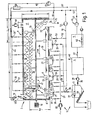
- FIG. 1 shows one Appendix 1 for the biological treatment of preferably wet Organic waste with several components, consisting of one Solid-state reactor 2 for treating the organic material and the processing stages 3 to 2 downstream of the reactor 5 for post-treatment and reprocessing of reusable Washing liquid.
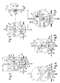
- the reactor 2 exists as shown in FIG. 1 from an elongated housing 6 with a vertical Cross section, as shown in Figures 2 to 5.
- the Length 1 of the housing can vary depending on the size of the system be designed differently and for example 1 20 to 30 m.
- the height h of the reactor room in this case h is 4 to 5 m.
- At the bottom is the reactor housing 6 'in cross section approximately cylindrical, in upper area 6 "rather rectangular (FIG. 2), triangular (Fig. 3) or overall oval (Fig. 4) educated.
- the reactor housing 6 is of a horizontal Shaft 7 penetrates, which preferably as a stirrer 8 with paddle or shovel-shaped circulating elements 9 is trained.
- the shaft 7 is driven by a Drive motor 10.
- the housing 6 of the Reactor 2 at its one upper left end in the figure a filling opening 11 through which the reactor according to arrow 12 with an organic load Material 13 is loaded.
- This is it especially wet organic materials or biomass, which in particular from biological waste in the household the food processing industry, agriculture or from an organic fraction of the residual waste (Landfill waste) or the like (organic waste).
- the reactor 2 shown in FIG. 1 is filled in its interior 17 up to a medium filling level h F with material 13, so that an air space 16 lying above it is established.
- the fill level of the material can be, for example, two thirds of the total height h.
- a plurality of spray arms 18 to act on the Material 13 with a wash-out liquid 19, which according to an arrow representation emerges from the spray arms 18.
- An upper feed line 20 with control valve 21 leads the Wash-out liquid 19 for the individual spray arms 18.
- In 1 are, for example, seven Spray arms 18 distributed over the length of the reactor interior arranged.
- the perforated screen diameter is between 6 and 12 mm and is in particular 8 mm in diameter. This diameter is symbolically represented by d 1 .
- the chamber 22 has a dual function. On the one hand, it serves to collect those passing through the material 13 Washing liquid. This washout liquid is 19 'in the chamber 22 is marked and is via a discharge line 24 with a valve arrangement 25 to a manifold 26 guided.
- the chamber 22 serves to act on the Material 13 with fresh air 27, as symbolically in Fig. 1st is shown with arrows.
- the fresh air is over a Compressor 28 fed to a manifold 29, and from there via control valves 30 via line 31 of the respective Chamber 22 fed.
- the lower manifold 26 for out of the chambers leached out wash liquid leads over a common Line 34 with valve arrangement 35 to the downstream Processing stages 3 to 5 for the treatment of Washing liquid.
- These treatment stages include in particular, first an impurity separator 3, which for Separation of all types of sediments such as B. sand, stones or the like, d. H. all substances that act as sediments penetrate the sieve 23.
- Settling agents are made via a Conveyor 36, floating or suspended matter such as Plastic, wood or the like are placed over one Skimmer device 37 removed from the contaminant separator.
- the cleaned in the impurity separator 3 Wash-out liquid is supplied to pump 39 via a line 38 a downstream anaerobic reactor stage 4, the is designed, for example, as a metane reactor.
- the meta-reactor becomes the one enriched with organic matter Wash liquid degraded by metanobacteria and cleaned, where biogas or meta gas 40 as Metabolic product is created.
- the downstream treatment level contains a further aerobic cleaning reactor 5, which has a Line 41 the anaerobic state of the washing liquid in transferred an aerobic state, with ventilation 42 for an aerobic decomposition and revitalization of the washing liquid worries.
- the so treated and cleaned and especially of strong organic washing liquid is disposed of a line 43 is removed from the aerobic cleaning stage 5 and a manifold 44 fed by a pump 45.
- This manifold 44 leads to the individual feed lines 20 to the spray arms 18.
- a washout liquid treated in this way persists a certain start-up phase of plant 1 from an easy acidified liquid, the acidification of the initially used pure water as a wash-out liquid through the aerobic treatment of the material 13 takes place in the reactor 2.
- This process corresponds to hydrolysis, i.e. H. one Dissolution of soluble salts with acidification of the water.
- the material 13 fed continuously or discontinuously to the inlet opening 11 of the reactor 2 generally consists of a wet organic substance, in particular of organic waste, as mentioned at the beginning.
- the fill level of the material 13 is approximately h F ⁇ 2/3 of the interior height h, so that an upper air space 16 is created. 2 to 5, the filling height h F is dimensioned such that almost the entire width B of the surface 46 of the material 13 can be sprayed with washing-out liquid 19.
- the upper region of the reactor is designed to be rectangular in cross-section (FIG. 2), triangular (FIG. 3) or overall oval (FIG. 4) in order to avoid a reduction in the material surface with a corresponding filling height.
- the uniform spraying of the material 13 through the Spray arms 18 by means of the slightly acidified liquid 19 causes a washout of soluble organic and / or inorganic substances and / or water-soluble fatty acids, which are formed by decomposition of the material 13.
- the upheaval it is also used, in particular, for vertical and to avoid horizontal short-circuit current channels by the liquid flow of the washing liquid in Material 13 would form, making it an uneven Wetting or washing out and thus dead zones would.
- the paddle-shaped or scoop-shaped stirring arms 9 can, as shown in Fig.
- the paddle-shaped end blades 9 can lie side by side or overlap so that it is too a kind of disk-shaped circulation of the material comes. Due to the rotational movement of the shaft 7 (arrow 47) takes place a slow longitudinal transport in the direction of arrow 48 through the reactor interior 17 instead of the material 13 slowly migrates lengthwise through the reactor and finally after a dwell time of e.g. B. 4 to 8 days Leaves reactor interior 17 through the discharge opening 14.
- Measuring devices are not shown in the reactor to record the most diverse parameters of the material such as e.g. B. its composition, its temperature, the Moisture content, etc. assigned, while still measurement data the washing liquid and the supply air are available. Depending on the progress of treatment, they can then be placed side by side ordered spray arms 18 with different Wash liquid to be applied to a different washout of the underlying one Obtain material composition. Equally, they can e.g. B. four lower chambers 22 of different strengths be supplied with fresh air 27 to the aerobic To influence the decomposition process of the material 13. Accordingly, the mixing of the Material also affects the Cause material properties.
- wash-out liquid 19 For example, at a certain increase in aerobic degradation of the material the surface of the organic material instead of what at the same time the wash-out process by the wash-out liquid 19 would favor. Therefore, depending on the degree the optimal amount of aerobic degradation Wash-out liquid are metered in, which is determined empirically can be. For example, a Increase in the temperature of the washout fluid due to the aerobic decomposition of the material favorably on the subsequent treatment levels 3 to 5 to ensure optimal To obtain regeneration of the washing liquid.
- a preferential treatment of the material in the entrance area as well in the end region of the reactor is in claims 3 and 4 described.
- the interior 17 of the reactor 2 can therefore by means of appropriate measuring devices monitored and the Process progress according to a given program or depending on the measured values.
- the adjacent lower chambers 22 are closed by means of the covering sieves 23 in such a way that the material 13 can largely not get into the chamber 22.
- the decisive factor here is the mesh size with the diameter d 1 .
- the screen 23 must be contaminated or constipation, which is caused by a Backwashing takes place.
- the chamber 22 existing and collected liquid 19 'either by Closure of the valves 25 pent up so that it becomes a Liquid surge inside chamber 22 comes up or it is cleaned via a manifold 51 of line 43, 44 Removed washout liquid and targeted over the chamber 22 Supply lines 52 supplied with valve arrangement 53 (see 4, 5).
- the liquid can go up to an upper one Liquid level 33 corresponding to the level of Overflow wall 32 are dammed up.
- Compressed air via the compressor 28 can do this in each case acted sieve 23 blown free and cleaned become.
- This process is also particularly by means of Liquid pump 45 or another pump 54 in the Manifold 51 supported.
- the cleaning process of the covering sieves 23 can also be carried out in this way that only one chamber or only certain Chambers are backwashed and the this causes rising backwash liquid in the adjacent or one of the adjacent chambers is dissipated.
- the first in FIG. 1 and third chamber 22 each in the adjacent chamber be emptied during the backwash process.
- the material 13 can be treated in a wide variety of ways with washing-out liquid 19 and with fresh air 27 with simultaneous or intermittent circulation of the material.
- washing-out liquid 19 and with fresh air 27 with simultaneous or intermittent circulation of the material.
- approx. 0.5 - 2 m 3 wash-out liquid per day and per ton of material are converted in the reactor.
- the duty cycle of the agitator can be between 5 to 60 min. per hour at a rotation of 1 to 2 times per minute.
- FIG. 3 shows a sole Fresh air supply 27 without washing out.
- FIG. 4 shows the backwashing process up to a liquid level with a liquid level 33 like previously described. This causes the material to float on it Liquid cushion on, so that the rotating agitator 8th can mix more easily. A slight increase in material inside the reactor is harmless during this mixing process.
- FIG. 2, 3 shows the process the fresh air supply via line 31 with valve arrangement 30 over the lower covering sieve 23 to material 13.
- the air serves for the aerobic degradation or the aerobic decomposition of the Material using microorganisms, the air in the upper Air space 16 collected and through the air outlet opening 50 is sucked out of the reactor interior 17.
- FIG. 5 shows the backwashing process via line 52 open valve 53, at the same time Pressurized air;
- Fig. 4 shows this process without Air pressure, d. H. closed valve 30.
- baffle 55 prevents that fresh material brought in unhindered on the Material surface 46 from the inlet 11 almost in the short circuit to Exit 14 can get.
- the fresh material must rather first on the path indicated by arrow 56 under the Baffle 55 through and the lower part of the reactor traverse.
- the material treated in the reactor may be sanitized before it leaves the solid-state reactor 2, ie to be exposed to a certain temperature for a certain time.
- This can expediently be done by additionally heating the rear container contents 13 over a certain distance l 1 ⁇ (1/3 - 1/4) 1.
- circulating water is withdrawn from line 43 via a line 57 connected in parallel, which is heated in a heat accumulator (not shown) or in a schematically illustrated heat exchanger 58.
- the circulating water of line 57 can then either be specifically added to the collecting line 44 in the upper region of the reactor or a specific application takes place, for example, via the supply line 20 in the rear reactor region. This is shown schematically in FIG. 1 via the last feed line 20 '.
- a suitable further development of the method can also be a continuous or discontinuous metering of Activated sludge or excess sludge from an activated sludge plant be in the area of the filling opening 11.
- the one with the Activated sludge introduced aerobic microorganisms a reaction accelerator for the biochemical implementation of organic materials.
- This addition is indicated by arrow 59 indicated schematically.
- Prove to be particularly advantageous already adapted to the waste Microorganisms that are either aerobic Percolate treatment stage or, for example, one biological leachate treatment plant can.
- the one indicated in the area of the outlet opening 14 Separation of the material flow 15 into a partial flow 15 ' enables partial recirculation of via line 60 material treated in the percolator 6.
- An additional Funding 61 can support this process. Through the partial recycling of treated in percolator 6 Material and the already adapted ones contained therein Microorganisms can also accelerate the reaction be effected. This is via the feed line 60 with an arrow 62 is shown schematically in the area of the filling opening 11.
- the agitator 8 has corresponding agitator arms or circulating elements on that lead radially away from the drive shaft 7.
- the agitator 8 also its direction at intervals to change.
- the stirring effect can be enhanced in which a blade-like rotation of the stirring arms 8 or Circulating elements with an angle of attack x according to FIG. 5 or also by an arcuate arrangement as shown in Fig. 6 is made. It is in the form of a scoop Arrangement of the agitator arms 8 with e designated. In the direction of rotation in the direction of arrow e achieved optimal mixing.
- at heavily soiled material 13 for example Plastic films and cords, etc.
- the lower can continue Sieve 23 can be cleaned by means of the agitator.
- a wear part 63 as Slider to be attached.
- This wearing part or this Scraper 63 at the ends of the agitator arm 8 can with a Clamping device 64, not shown, via the additional opening 65 introduced from the outside, readjusted or be replaced.
- the agitator 8 can furthermore be displaced eccentrically, preferably downwards, by a distance z from the cylinder longitudinal axis 66.
- the agitator radius R 2 is smaller than the cylindrical container radius R 1 , so that the wipers 63 are thereby only effective on the lower sieve 23 and do not cause undesired wear on the inner wall of the container.
- stirrer arms 8 advantageously also rotated by an angle y on the shaft 8 to be appropriate.
- Such a rotation of the stirring arms causes similar to a propeller a shovel effect and thus an axial feed parallel to the longitudinal axis of the Stirrer shaft 7.
- the stirrer shaft 7 in Twisted arrow direction e, the material 13 is in the Direction of flow g transported.
- the material is in the direction of Arrow h shifted.
- the rotary movement of the agitator shaft 7 can consequently with the propeller-like twisted arms Push the material forward or backward.
- the invention is not based on that shown and described Embodiment limited. Rather, it also includes professional training within the scope of Property rights claims.
Claims (20)
- Procédé de traitement biologique de déchets organiques, et en particulier de déchets biologiques (bio-ordures) d'origine domestique, de l'industrie de transformation des produits alimentaires, de l'agriculture ou analogue, avec un réacteur pour matériaux solides (2) dans lequel le matériau est traité, le réacteur (2) étant alimenté en continu ou en discontinu par du matériau (13), l'alimentation s'effectuant à une extrémité, le prélèvement à l'autre extrémité de réacteur (2), un dispositif d'agitation et/ou de mise en circulation (7 à 10) combiné étant en outre associé au réacteur (2) et servant à effectuer un mélange intime du matériau, une décomposition aérobie des substances organiques avec apport d'air frais (27) et d'eau étant effectuée, le matériau étant chauffé dans le réacteur à la température du processus,
caractérisé en ce quependant la décomposition aérobie du matériau, est effectué une extraction par lavage continu ou discontinu, au moyen d'un liquide d'extraction par lavage (19),les substances solubles, organiques et non-organiques ainsi que, le cas échéant, les acides gras solubles dans l'eau sont transférés du matériau (13) à traiter et passés dans le liquide d'extraction par lavage, et le liquide d'extraction par lavage ainsi chargé est prélevé de la partie inférieure du réacteur (2),le liquide d'extraction par lavage prélevé du réacteur (2) est soumis à un retraitement dans le sens d'une régénération et est appliqué de nouveau, au moyen de bras de pulvérisation (18), dans le réacteur (2) sur toute la surface de matériau, le dispositif d'agitation et/ou de mise en circulation (7 à 10) servant simultanément de dispositif de transport pour assurer le transport du matériau, en évitant et/ou en détruisant simultanément la formation de canaux de court-circuit pour le liquide d'extraction par lavage. - Procédé selon la revendication 1,
caractérisé en ce que
le matériau (13) est susceptible d'être transporté dans réacteur (2), par déplacement en avant ou en arrière sur sa longueur (1), l'exposition du matériau à du liquide d'extraction par lavage (19) et/ou à de l'air frais (27) sur la longueur (1) du réacteur s'effectuant, de préférence, régulièrement ou étant soumise à une variation, selon la composition du matériau. - Procédé selon la revendication 1,
caractérisé en ce que,
dans la zone d'introduction (11) du réacteur (2), s'effectue de préférence une exposition régulière du matériau au liquide d'extraction par lavage (19) est simultanément un apport d'air frais (27) fait à dessein, la décomposition aérobie du matériau, d'une part, provoquant un échauffement à dessein du matériau (13) et du liquide d'extraction par lavage (19) et le liquide d'extraction par lavage, d'autre part, provoquant une évacuation par lavage intense des substances solubles organiques et/ou non-organiques et/ou des acides gras solubles dans l'eau. - Procédé selon la revendication 1,
caractérisé en ce que
dans la zone d'évacuation dotée de l'ouverture d'évacuation (14) du réacteur (2), s'effectue de préférence une exposition diminuée ou stoppée au liquide d'extraction par lavage (19) et/ou un apport d'air frais (27) amplifié, dans le but de réduire la teneur en eau (séchage) du matériau dans cette zone, de préférence dans la zone d'évacuation une hygiénisation du matériau et réalisée avec amenée d'un liquide de retour (19) préchauffé sur un intervalle de temps déterminé. - Procédé selon l'une des revendications 1 à 4,
caractérisé en ce que
le traitement du matériau (13) dans le réacteur (2) s'effectue en fonction de sa charge organique, de sa température, de sa teneur en eau, par une décomposition aérobie et/ou par un processus d'extraction par lavage des substances solubles, organiques, non organiques, ou des acides gras solubles dans l'eau, avec mise en circulation continue ou discontinue du matériau, de façon commandée et/ou régulée. - Procédé selon l'une des revendications 1 à 5, caractérisé en ce que
le réacteur présente une enceinte à air (16) libre située au-dessus du matériau (13) qui permet d'arroser ou d'exposer de façon aussi régulière que possible la surface d'arrosage (46) supérieure maximale possible. - Procédé selon l'une des revendications 1 à 6,
caractérisé en ce que
le réacteur (2) présente dans sa zone inférieure au moins deux chambres (22) qui sert à l'amenée d'air frais (27) et/ou d'évacuation du liquide d'extraction par lavage (19'), les chambres étant séparées de l'espace intérieur de réacteur (17) par l'intermédiaire d'un dispositif de filtration et, en particulier, de tamisage (23), dans le but d'éviter toute pénétration de solides. - Procédé selon la revendication 7,
caractérisé en ce qu'
un dispositif de tamisage (23) est nettoyé au moyen d'un processus à rinçage à contre-courant dans la direction de l'espace intérieur de réacteur (17) par inondation de la chambre (22), le liquide de rinçage à contre-courant pouvant être amené de préférence à une autre chambre et de préférence à une chambre disposée à côté. - Procédé selon la revendication 8,
caractérisé en ce que
le processus de rinçage à contre-courant s'effectue par insufflation d'air sous pression, dans la direction de l'espace intérieur de réacteur (17). - Procédé selon l'une des revendications 7 à 9,
caractérisé en ce que
le réacteur (2) est inondé par la chambre (22) avec du liquide d'extraction par lavage (19), de manière que le matériau (13) soit mis en flottation sur le liquide et que, de préférence, le matériau flottant (13) soit mis en circulation, respectivement transporté dans le sens avant et/ou dans le sens arrière dans le réacteur, au moyen du dispositif agitateur (7 à 10). - Procédé selon l'une des revendications 1 à 10 précédentes,
caractérisé en ce que
le dispositif d'agitation et/ou de mise en circulation est réalisé sous la forme de dispositif agitateur à ergots, équipé d'un bras agitateur (8) et d'un arbre (7) horizontal, traversant l'espace intérieur de réacteur (17), et en ce que le matériau (13) est travaillé dans le sens d'une mise en circulation en forme de disque, de préférence un type de progression en forme de disque ou en forme de bouchon du matériau (13) dans l'espace intérieur de réacteur (17) étant effectuée. - Procédé selon l'une des revendications précédentes,
caractérisé en ce que
le liquide d'extraction par lavage (19') prélevé du réacteur (2) est amené à des étages de traitement (3 à 5) subséquents, dans lesquels le liquide est soumis à un processus de traitement de nature mécanique et/ou anaérobie et/ou aérobie subséquent pour épurer ou régénérer, et en ce que le liquide d'extraction par lavage ainsi traité est amené de préférence pour un rinçage à contre-courant des chambres (22) et/ou à l'enceinte libre (16) située au-dessus du matériau (13) dans le réacteur (6). - Procédé selon la revendication 12,
caractérisé en ce queles étages de traitement (3 à 5) comprennent un séparateur à substances parasites (3) destiné à séparer les substances non-flottantes telles que le sable, les pierres ou analogues, séparateur dans lequel les substances flottantes mises en flottaison, telle que la matière plastique, le bois, ou analogues, peuvent être extraites,de préférence, en plus, les étages de traitement (3 à 5) comprennent un réacteur à méthane (4), anaérobie, monté en aval, pour le traitement du liquide d'extraction par lavage, le liquide d'extraction par lavage ayant été enrichi en produits organiques étant décomposé et épuré par des bactéries méthanogènes avec formation de biogaz (40) à titre de produit du métabolisme,le liquide d'extraction par lavage, ainsi épuré, est amené de préférence à un étage d'épuration (5) aérobie subséquent, dans lequel peut être constitué un état aérobie, etle liquide d'extraction par lavage ainsi épuré et régénéré peut être ramené de nouveau au réacteur (2). - Procédé selon la revendication 13,
caractérisé en ce que
pour accélérer la réaction, on amène de façon dosée dans la zone d'introduction (11), de la boue activée venant d'une installation d'activation aérobie (59). - Procédé selon la revendication 14,
caractérisé en ce que
pour accélérer la réaction, une quantité partielle (15) de matériau traité (13) est retournée de l'évacuation (14) et amenée de façon dosée (62) dans la zone d'introduction (11). - Dispositif de traitement biologique de déchets organiques et, en particulier, de déchets biologiques (bio-ordures) d'origine domestique, de l'industrie de transformation des produits alimentaires, de l'agriculture ou analogues, selon une ou plusieurs des revendications précédentes, avec un réacteur à solides (2), dont l'ouverture d'introduction (11) ainsi que l'ouverture d'évacuation (14) sont disposées diamétralement opposées pour le matériau (13) à introduire,
caractérisé en ce quele réacteur (2) est traversé, dans la direction longitudinale et/ou de transport du matériau, par un arbre (7) mis en mouvement, de façon réversible, horizontale, destiné à un dispositif d'agitation, de mélange intime et de transport (8 à 10) mis en mouvement, et,dans l'espace intérieur de réacteur (17) sont prévus, répartis sur sa longueur 1, des bras de pulvérisation ou aspersion (18) destinés au liquide d'extraction par lavage (19), des chambres (22) étant prévues dans la zone de fond du réacteur (2) pour recevoir le liquide (19) et/ou pour l'amenée d'air frais (27). - Dispositif selon la revendication 16,
caractérisé en ce que
le dispositif agitateur est réalisé sous la forme de dispositif agitateur à ergots (8) avec des bras agitateurs ou des organes de mise en circulation (8, 9) en forme de palettes et/ou d'aubes, les bras agitateurs (8, 9) étant susceptibles de tourner, de préférence à la façon d'une hélice, en vue de générer un mouvement dirigé vers l'avant ou vers l'arrière. - Dispositif selon la revendication 16,
caractérisé en ce que
les organes de mise en circulation (9) en forme de palettes ou en forme d'aubes sont disposés sur un arbre (7), en position opposée et/ou les uns à côté des autres en se chevauchant. - Dispositif selon l'une des revendications 16 à 18,
caractérisé en ce que
les bras du dispositif agitateur sont décalés d'un angle x par rapport à un axe de symétrie radial et, en particulier, sont disposés obliquement ou ont une allure bombée. - Dispositif selon la revendication 16,
caractérisé en ce qu'
un dispositif de transport (61) est prévu pour assurer le recyclage du matériau (13) traité, par une conduite de transport (60) allant à l'entrée (11).
Applications Claiming Priority (3)
| Application Number | Priority Date | Filing Date | Title |
|---|---|---|---|
| DE19602489 | 1996-01-25 | ||
| DE19602489A DE19602489A1 (de) | 1996-01-25 | 1996-01-25 | Verfahren zur biologischen Behandlung von organischen Materialien und Vorrichtung zur Durchführung des Verfahrens |
| PCT/EP1997/000341 WO1997027158A1 (fr) | 1996-01-25 | 1997-01-24 | Procede pour le traitement biologique de matieres organiques et dispositif pour la mise en oeuvre du procede |
Publications (2)
| Publication Number | Publication Date |
|---|---|
| EP0876311A1 EP0876311A1 (fr) | 1998-11-11 |
| EP0876311B1 true EP0876311B1 (fr) | 1999-08-18 |
Family
ID=7783557
Family Applications (1)
| Application Number | Title | Priority Date | Filing Date |
|---|---|---|---|
| EP97901083A Expired - Lifetime EP0876311B1 (fr) | 1996-01-25 | 1997-01-24 | Procede pour le traitement biologique de matieres organiques et dispositif pour la mise en oeuvre du procede |
Country Status (11)
| Country | Link |
|---|---|
| US (1) | US6110727A (fr) |
| EP (1) | EP0876311B1 (fr) |
| JP (1) | JP4104168B2 (fr) |
| KR (1) | KR100456044B1 (fr) |
| CN (1) | CN1101797C (fr) |
| AT (1) | ATE183489T1 (fr) |
| AU (1) | AU715298B2 (fr) |
| DE (2) | DE19602489A1 (fr) |
| ES (1) | ES2137773T3 (fr) |
| GR (1) | GR3031863T3 (fr) |
| WO (1) | WO1997027158A1 (fr) |
Families Citing this family (62)
| Publication number | Priority date | Publication date | Assignee | Title |
|---|---|---|---|---|
| DE19744653A1 (de) * | 1997-10-09 | 1999-04-15 | Christian Quirrenbach | Anlage zur Erzeugung von Biogas und ein Verfahren zum Betreiben der Anlage |
| ES2199608T3 (es) | 1998-11-06 | 2004-02-16 | Patrick Muller | Procedimiento y dispositivo para preparar una mezcla de sustancias que contienen componentes organicos. |
| DE19909353A1 (de) * | 1998-11-06 | 2000-05-11 | Patrick Mueller | Verfahren und Vorrichtung zur Aufbereitung eines Organik enthaltenden Stoffgemisches |
| AU3789100A (en) * | 1998-11-06 | 2000-05-29 | Christian Widmer | Method for utilizing waste |
| US6352855B1 (en) * | 1999-01-12 | 2002-03-05 | Paul E. Kerouac | In-vessel composting process and apparatus |
| WO2000042164A1 (fr) * | 1999-01-12 | 2000-07-20 | Paul Kerouac | Procede et dispositif de compostage en circuit ferme |
| US6495181B1 (en) * | 1999-01-22 | 2002-12-17 | Bush Brothers & Company | Soak apparatus for leaching soluble constituents from insoluble materials |
| DE10005149A1 (de) * | 2000-02-07 | 2001-08-23 | Daniel Friedli | Trocknungsverfahren |
| DE10029668A1 (de) * | 2000-06-23 | 2002-01-03 | Biosal Anlagenbau Gmbh | Bioreaktor zur mikrobiellen Konvertierung stückiger und/oder pastöser Stoffe |
| DE10253024B4 (de) * | 2002-11-14 | 2008-02-21 | SATTLER, Jörg | Verfahren zur mikrobiellen aeroben Konversion von biogenen organischen Frisch- und/oder Abfallmaterialien |
| JP2004330093A (ja) * | 2003-05-08 | 2004-11-25 | Mutsuro Bunto | リサイクル土壌製造装置 |
| CA2468158C (fr) * | 2003-08-14 | 2006-05-23 | Brian Joseph Forrestal | Systeme et methode pour la fabrication de biogaz et de compost |
| EP1754553B1 (fr) * | 2004-05-25 | 2009-04-15 | Koai Industry Co., Ltd. | Dispositif de traitement des déchets |
| ITRM20040297A1 (it) * | 2004-06-17 | 2004-09-17 | Sorain Cecchini Ambiente Sca Spa | Metodo per la realizzazione del riciclaggio integrale a basso impatto ambientale dei rifiuti solidi urbani e dispositivi di attuazione. |
| DE102004053615B3 (de) * | 2004-11-03 | 2006-05-18 | Brandenburgische Technische Universität Cottbus | Abbauverfahren von biogenem Material |
| WO2006089766A1 (fr) * | 2005-02-24 | 2006-08-31 | Christian Widmer | Procede et reacteur de traitement biologique de dechets organiques |
| CN1868918B (zh) * | 2005-05-27 | 2013-01-09 | 李宾 | 废水处理工艺流程及设备 |
| DE202006002757U1 (de) * | 2006-02-21 | 2007-06-28 | Bekon Energy Technologies Gmbh & Co. Kg | Bioreaktor zur Methanisierung von Biomasse mit hohem Feststoffanteil |
| CN100462339C (zh) * | 2006-06-15 | 2009-02-18 | 张相锋 | 半固态有机废物高温消化装置 |
| DE102006058419A1 (de) * | 2006-12-08 | 2008-06-26 | Bilfinger Berger Umwelttechnik Gmbh | Verfahren zur Perkolataufbereitung und Perkolataufbereitungsanlage |
| KR100832785B1 (ko) * | 2007-04-20 | 2008-05-27 | 고천일 | 음식물쓰레기 소멸처리시스템장치 |
| ES2331395B1 (es) * | 2007-12-07 | 2010-07-16 | Universidad De Huelva | Reactor experimental para ensayos de investigacion de compostaje. |
| US20090145188A1 (en) * | 2007-12-07 | 2009-06-11 | Halton Recycling Limited | Apparatus and methods for generating compost |
| DE102008030653B4 (de) * | 2007-12-30 | 2012-02-23 | Archea Biogastechnologie Gmbh | Verfahren und Anlage zur Steigerung der Biogasausbeute eines Substrats |
| WO2010042700A2 (fr) * | 2008-10-08 | 2010-04-15 | Global Composting Technologies, Llc | Appareil de compostage aérobie |
| US9713812B1 (en) | 2011-09-12 | 2017-07-25 | Organic Energy Corporation | Methods and systems for separating and recovering recyclables using a comminution device |
| CA2818920C (fr) * | 2010-11-24 | 2022-01-04 | Organic Energy Corporation | Separation mecanisee de materiaux humides et secs dans un courant de dechets solides |
| CA2743833C (fr) | 2011-04-15 | 2017-11-21 | 2245396 Ontario Inc. | Systeme de gestion de dechets alimentaires |
| US8685716B2 (en) | 2011-05-10 | 2014-04-01 | Great Wall Of China Waste Company Inc. | Composting apparatus and method |
| CN102233352A (zh) * | 2011-06-24 | 2011-11-09 | 东南大学 | 一种用于粘结体的分离装置 |
| US8329455B2 (en) | 2011-07-08 | 2012-12-11 | Aikan North America, Inc. | Systems and methods for digestion of solid waste |
| EP2554638B1 (fr) * | 2011-08-01 | 2019-05-08 | Zweckverband Abfallbehandlung Kahlenberg | Procédé et dispositif de traitement mécanique ou mécanique-biologique des déchets |
| GB201113754D0 (en) | 2011-08-09 | 2011-09-21 | Glaxo Group Ltd | Composition |
| WO2013053697A2 (fr) * | 2011-10-12 | 2013-04-18 | Berthold Warth | Procédé de préparation et de valorisation de biomasse |
| US9096822B2 (en) * | 2012-01-18 | 2015-08-04 | Zero Waste Energy, LLC. | Device to produce biogas |
| CN102584377A (zh) * | 2012-02-13 | 2012-07-18 | 侯澄友 | 一种用于发酵槽制备生物有机肥的翻抛曝气装置 |
| DE102012005527A1 (de) * | 2012-03-21 | 2013-09-26 | Obermeier - Widmann GbR (vertretungsberechtigte Gesellschafter August Obermeier, 84419 Schwindegg; Christine Widmann, 92318 Neumarkt) | Biogasanlage mit einem ersten und einem zweiten Behälterraum |
| WO2014198274A1 (fr) * | 2013-06-12 | 2014-12-18 | Renescience A/S | Procede de traitement de dechets menagers solides (msw) utilisant une hydrolyse et une fermentation microbiennes |
| CN102861762B (zh) * | 2012-09-27 | 2014-10-29 | 江苏维尔利环保科技股份有限公司 | 有机垃圾厌氧消化处理方法 |
| CN102989745B (zh) * | 2012-12-06 | 2014-08-13 | 江苏维尔利环保科技股份有限公司 | 处理生活垃圾的淋滤机械生物反应器 |
| WO2014117779A2 (fr) * | 2013-01-30 | 2014-08-07 | Xergi Nix Technology A/S | Système de prétraitement de biomasse et procédé correspondant |
| DE202013003199U1 (de) | 2013-04-08 | 2013-07-01 | Zweckverband Abfallbehandlung Kahlenberg | Vorrichtung zur mechanischen oder mechanisch-biologischen Behandlung von Abfällen |
| CN103392439B (zh) * | 2013-07-10 | 2015-10-14 | 中国农业科学院农业资源与农业区划研究所 | 固/液肥料转换器 |
| WO2015040677A1 (fr) * | 2013-09-17 | 2015-03-26 | 広愛産業株式会社 | Dispositif de traitement des déchets |
| US11180391B2 (en) * | 2013-10-02 | 2021-11-23 | Anaergia B.V. | Method and device for processing solid waste |
| NL1040425C2 (nl) | 2013-10-02 | 2015-04-07 | Technologies Holding B V D | Werkwijze en inrichting voor het scheiden van lichtere deeltjes en zwaardere deeltjes. |
| US20150273719A1 (en) | 2014-04-01 | 2015-10-01 | Mccain Foods Limited | Blade assembly and food cutting device incorporating the same |
| CN104162515B (zh) * | 2014-08-04 | 2017-03-29 | 陈化学 | 厨余垃圾分选装置 |
| CN104588391B (zh) * | 2014-12-24 | 2017-01-04 | 邵宇 | 一种便捷式餐厨垃圾处理系统 |
| CN104722556A (zh) * | 2015-02-09 | 2015-06-24 | 大连泰达环保有限公司 | 一种高效生活垃圾双螺旋搅拌淋滤处理反应器 |
| CN108472696A (zh) | 2015-11-02 | 2018-08-31 | 安那吉亚有限责任公司 | 用于处理固体废物的方法和装置 |
| CN105462821A (zh) * | 2016-01-15 | 2016-04-06 | 河南省立丰实业有限公司 | 大型卧式隧道窑型螺旋连续干式厌氧发酵设备 |
| US10035734B2 (en) * | 2016-03-10 | 2018-07-31 | James Chun Koh | Food waste treatment apparatus |
| CN105903754B (zh) * | 2016-07-01 | 2018-09-07 | 香港生产力促进局 | 一种自动分类有机垃圾处理系统 |
| US20180148391A1 (en) * | 2016-11-30 | 2018-05-31 | Greenscience Technologies Inc. | Vermicast production through conversion of biodegradable organic matter |
| GB201621685D0 (en) | 2016-12-20 | 2017-02-01 | Glaxosmithkline Consumer Healthcare (Uk) Ip Ltd | Novel composition |
| CN107443871B (zh) * | 2017-09-23 | 2019-03-05 | 温州华正包装股份有限公司 | 凹版印刷机油墨循环利用系统 |
| US11203735B2 (en) * | 2017-11-17 | 2021-12-21 | Power Knot Inc. | Hose on waste food machine used to clean food processing machine |
| CN212041968U (zh) * | 2018-07-10 | 2020-12-01 | 雅高环保(香港)有限公司 | 用于处理食品废物的系统 |
| DE102018120565A1 (de) | 2018-08-23 | 2020-02-27 | Bma Braunschweigische Maschinenbauanstalt Ag | Verfahren und Vorrichtung zum Aufbereiten eines Gemisches |
| CN212894495U (zh) * | 2020-07-09 | 2021-04-06 | 河北科技大学 | 一种有机废弃物资源化处理系统 |
| GB202214700D0 (en) | 2022-10-06 | 2022-11-23 | GlaxoSmithKline Consumer Healthcare UK IP Ltd | Dentifrice composition |
Family Cites Families (9)
| Publication number | Priority date | Publication date | Assignee | Title |
|---|---|---|---|---|
| NL8006567A (nl) * | 1980-04-03 | 1981-11-02 | Inst Voor Bewaring | Werkwijze voor het anaeroob composteren van vast organisch afvalmateriaal. |
| DE3545679A1 (de) * | 1985-12-21 | 1987-06-25 | Messerschmitt Boelkow Blohm | Verfahren zur entsorgung der organischen hausmuellfraktion |
| NL9200751A (nl) * | 1992-04-24 | 1993-11-16 | Vam Nv | Werkwijze voor het verwerken van groente-fruit-tuin-afval. |
| US5288399A (en) * | 1992-08-28 | 1994-02-22 | Schulz Christopher R | Gravity flow filter with backwash control chamber |
| EP0703824A4 (fr) * | 1993-06-14 | 1997-11-19 | Agustin H Arrau | Procede de compostage combine et installation de traitement de dechets solides et de boues d'egouts |
| CH685494A5 (de) * | 1993-09-08 | 1995-07-31 | Buehler Ag | Verfahren und Anlage zur Vergärung von Bioabfall. |
| DE4343767C1 (de) * | 1993-12-21 | 1995-02-16 | Metallgesellschaft Ag | Verfahren zur Verminderung des Schadstoffgehalts und zur Senkung des Ammoniumgehalts sowie der CSB- und BSB¶5¶-Werte im Abwasser aus der Kompostierung |
| WO1995020554A1 (fr) * | 1994-01-31 | 1995-08-03 | James Wright | Dispositif de compostage continu |
| US5846815A (en) * | 1997-05-13 | 1998-12-08 | Wright; James | Continuous composter having self contained aerating zones |
-
1996
- 1996-01-25 DE DE19602489A patent/DE19602489A1/de not_active Withdrawn
-
1997
- 1997-01-24 AU AU14452/97A patent/AU715298B2/en not_active Ceased
- 1997-01-24 WO PCT/EP1997/000341 patent/WO1997027158A1/fr active IP Right Grant
- 1997-01-24 JP JP52656397A patent/JP4104168B2/ja not_active Expired - Fee Related
- 1997-01-24 AT AT97901083T patent/ATE183489T1/de not_active IP Right Cessation
- 1997-01-24 KR KR10-1998-0705693A patent/KR100456044B1/ko not_active IP Right Cessation
- 1997-01-24 EP EP97901083A patent/EP0876311B1/fr not_active Expired - Lifetime
- 1997-01-24 US US09/117,335 patent/US6110727A/en not_active Expired - Fee Related
- 1997-01-24 ES ES97901083T patent/ES2137773T3/es not_active Expired - Lifetime
- 1997-01-24 CN CN97191862A patent/CN1101797C/zh not_active Expired - Fee Related
- 1997-01-24 DE DE59700352T patent/DE59700352D1/de not_active Expired - Fee Related
-
1999
- 1999-11-17 GR GR990402957T patent/GR3031863T3/el unknown
Also Published As
| Publication number | Publication date |
|---|---|
| JP2000504267A (ja) | 2000-04-11 |
| KR100456044B1 (ko) | 2005-02-24 |
| ATE183489T1 (de) | 1999-09-15 |
| KR19990081975A (ko) | 1999-11-15 |
| CN1209794A (zh) | 1999-03-03 |
| GR3031863T3 (en) | 2000-02-29 |
| JP4104168B2 (ja) | 2008-06-18 |
| AU1445297A (en) | 1997-08-20 |
| EP0876311A1 (fr) | 1998-11-11 |
| ES2137773T3 (es) | 1999-12-16 |
| US6110727A (en) | 2000-08-29 |
| DE59700352D1 (de) | 1999-09-23 |
| DE19602489A1 (de) | 1997-07-31 |
| CN1101797C (zh) | 2003-02-19 |
| AU715298B2 (en) | 2000-01-20 |
| WO1997027158A1 (fr) | 1997-07-31 |
Similar Documents
| Publication | Publication Date | Title |
|---|---|---|
| EP0876311B1 (fr) | Procede pour le traitement biologique de matieres organiques et dispositif pour la mise en oeuvre du procede | |
| DE3844700C2 (de) | Verfahren und vorrichtung zur biologischen aufbereitung organischer stoffe | |
| DE2636535C3 (de) | Fermentationsbehälter zur aeroben Kompostherstellung | |
| EP1127034B1 (fr) | Procede et dispositif de preparation d'un melange de materiaux contenant des composants organiques | |
| DE2519618C3 (de) | Vorrichtung zur maschinellen Schnell-Kompostierung von Klärschlamm und anderen flüssigen, halbfesten oder festen Abfallstoffen sowie von Gemischen aus diesen | |
| DE19624268C2 (de) | Verfahren und Vorrichtung zur Verwertung organischer Abfälle | |
| DE69434054T2 (de) | Kompostierungsanlage für organische abfälle und verfahren zur kompostierung dieser abfälle | |
| DE102005057978A1 (de) | Fermentationseinrichtung mit gekoppeltem Substrat- und Sedimenttransport und Verfahren zum Betrieb der Fermentationseinrichtung | |
| WO2005118147A2 (fr) | Desintegrateur, reacteur pour l'hydrolyse et/ou le rouissage humide et installation de traitement des dechets equipee desdits desintegrateur et reacteur | |
| WO2005118147A9 (fr) | Desintegrateur, reacteur pour l'hydrolyse et/ou le rouissage humide et installation de traitement des dechets equipee desdits desintegrateur et reacteur | |
| DE102005026027A1 (de) | Stofflöser, Reaktor für Hydrolyse und/oder Nassrotte und Abfallaufbereitungsanlage mit einem derartigen Stofflöser und Reaktor | |
| DE102004025318A1 (de) | Verfahren und Vergärungsanlage zum anaeroben Vergären von biogenem Abfall | |
| EP2554638B1 (fr) | Procédé et dispositif de traitement mécanique ou mécanique-biologique des déchets | |
| EP0181615B1 (fr) | Procédé et installation pour la récupération et la revalorisation des boues d'épuration et des biodéchets | |
| EP2928845A2 (fr) | Procédé et dispositif pour séparer la phase solide de la phase liquide dans des liquides contenant des corps en suspension | |
| DE202007017166U1 (de) | Kompakt-Biogasanlage | |
| DE3228895A1 (de) | Verfahren zur gewinnung von biogas und vorrichtung zur durchfuehrung dieses verfahrens | |
| DE4312923C2 (de) | Verfahren zur Aufbereitung von als Bio-Wertstoffe anfallenden, aus pflanzlichen Stoffen bestehenden Abfallprodukten und von aus pflanzlichen Stoffen hergestellten Produkten, insbesondere Nahrungsmittelabfällen, zu wiederverwertbaren Stoffen | |
| DE19846336A1 (de) | Verfahren sowie Anlage zur Behandlung von Abfällen | |
| CH325848A (de) | Verfahren und Apparat zum Vergären organischer Abfallprodukte | |
| EP0659695B1 (fr) | Procédé pour le traitement des boues des eaux d'égou | |
| DE2253477A1 (de) | Verfahren und vorrichtung zum nasskompostieren organischer schlaemme | |
| EP1064240A1 (fr) | Procede et installation pour traiter des dechets | |
| EP0035112B1 (fr) | Procédé et dispositif pour le traitement de déchets solides et liquides, en particulier putrescibles | |
| DE19807116A1 (de) | Verfahren und Anlage zum Abscheiden bzw. -trennen von Schwer- und Leichtstoffen aus einer Suspension |
Legal Events
| Date | Code | Title | Description |
|---|---|---|---|
| PUAI | Public reference made under article 153(3) epc to a published international application that has entered the european phase |
Free format text: ORIGINAL CODE: 0009012 |
|
| 17P | Request for examination filed |
Effective date: 19980620 |
|
| AK | Designated contracting states |
Kind code of ref document: A1 Designated state(s): AT BE CH DE DK ES FI FR GB GR IE IT LI LU NL PT SE |
|
| GRAG | Despatch of communication of intention to grant |
Free format text: ORIGINAL CODE: EPIDOS AGRA |
|
| 17Q | First examination report despatched |
Effective date: 19981125 |
|
| GRAG | Despatch of communication of intention to grant |
Free format text: ORIGINAL CODE: EPIDOS AGRA |
|
| GRAH | Despatch of communication of intention to grant a patent |
Free format text: ORIGINAL CODE: EPIDOS IGRA |
|
| GRAH | Despatch of communication of intention to grant a patent |
Free format text: ORIGINAL CODE: EPIDOS IGRA |
|
| GRAA | (expected) grant |
Free format text: ORIGINAL CODE: 0009210 |
|
| AK | Designated contracting states |
Kind code of ref document: B1 Designated state(s): AT BE CH DE DK ES FI FR GB GR IE IT LI LU NL PT SE |
|
| REF | Corresponds to: |
Ref document number: 183489 Country of ref document: AT Date of ref document: 19990915 Kind code of ref document: T |
|
| REG | Reference to a national code |
Ref country code: CH Ref legal event code: EP |
|
| REF | Corresponds to: |
Ref document number: 59700352 Country of ref document: DE Date of ref document: 19990923 |
|
| REG | Reference to a national code |
Ref country code: IE Ref legal event code: FG4D Free format text: GERMAN |
|
| ITF | It: translation for a ep patent filed |
Owner name: UFFICIO TECNICO ING. A. MANNUCCI |
|
| ET | Fr: translation filed | ||
| GBT | Gb: translation of ep patent filed (gb section 77(6)(a)/1977) |
Effective date: 19991111 |
|
| REG | Reference to a national code |
Ref country code: ES Ref legal event code: FG2A Ref document number: 2137773 Country of ref document: ES Kind code of ref document: T3 |
|
| REG | Reference to a national code |
Ref country code: PT Ref legal event code: SC4A Free format text: AVAILABILITY OF NATIONAL TRANSLATION Effective date: 19991110 |
|
| REG | Reference to a national code |
Ref country code: DK Ref legal event code: T3 |
|
| PLBE | No opposition filed within time limit |
Free format text: ORIGINAL CODE: 0009261 |
|
| STAA | Information on the status of an ep patent application or granted ep patent |
Free format text: STATUS: NO OPPOSITION FILED WITHIN TIME LIMIT |
|
| 26N | No opposition filed | ||
| REG | Reference to a national code |
Ref country code: GB Ref legal event code: IF02 |
|
| REG | Reference to a national code |
Ref country code: GB Ref legal event code: 732E |
|
| PGFP | Annual fee paid to national office [announced via postgrant information from national office to epo] |
Ref country code: LU Payment date: 20090203 Year of fee payment: 13 Ref country code: ES Payment date: 20090219 Year of fee payment: 13 Ref country code: DK Payment date: 20090213 Year of fee payment: 13 Ref country code: AT Payment date: 20090130 Year of fee payment: 13 |
|
| PGFP | Annual fee paid to national office [announced via postgrant information from national office to epo] |
Ref country code: PT Payment date: 20090123 Year of fee payment: 13 Ref country code: NL Payment date: 20090131 Year of fee payment: 13 Ref country code: FI Payment date: 20090130 Year of fee payment: 13 Ref country code: DE Payment date: 20090206 Year of fee payment: 13 |
|
| PGFP | Annual fee paid to national office [announced via postgrant information from national office to epo] |
Ref country code: GR Payment date: 20090130 Year of fee payment: 13 Ref country code: CH Payment date: 20090217 Year of fee payment: 13 |
|
| PGFP | Annual fee paid to national office [announced via postgrant information from national office to epo] |
Ref country code: SE Payment date: 20090130 Year of fee payment: 13 Ref country code: IT Payment date: 20090130 Year of fee payment: 13 |
|
| PGFP | Annual fee paid to national office [announced via postgrant information from national office to epo] |
Ref country code: BE Payment date: 20090408 Year of fee payment: 13 |
|
| PGFP | Annual fee paid to national office [announced via postgrant information from national office to epo] |
Ref country code: FR Payment date: 20090130 Year of fee payment: 13 |
|
| BERE | Be: lapsed |
Owner name: *WIDMER CHRISTIAN Effective date: 20100131 |
|
| REG | Reference to a national code |
Ref country code: PT Ref legal event code: MM4A Free format text: LAPSE DUE TO NON-PAYMENT OF FEES Effective date: 20100726 |
|
| REG | Reference to a national code |
Ref country code: NL Ref legal event code: V1 Effective date: 20100801 |
|
| REG | Reference to a national code |
Ref country code: CH Ref legal event code: PL |
|
| REG | Reference to a national code |
Ref country code: DK Ref legal event code: EBP |
|
| EUG | Se: european patent has lapsed | ||
| REG | Reference to a national code |
Ref country code: FR Ref legal event code: ST Effective date: 20100930 |
|
| PG25 | Lapsed in a contracting state [announced via postgrant information from national office to epo] |
Ref country code: NL Free format text: LAPSE BECAUSE OF NON-PAYMENT OF DUE FEES Effective date: 20100801 Ref country code: LI Free format text: LAPSE BECAUSE OF NON-PAYMENT OF DUE FEES Effective date: 20100131 Ref country code: FR Free format text: LAPSE BECAUSE OF NON-PAYMENT OF DUE FEES Effective date: 20100201 Ref country code: CH Free format text: LAPSE BECAUSE OF NON-PAYMENT OF DUE FEES Effective date: 20100131 |
|
| PG25 | Lapsed in a contracting state [announced via postgrant information from national office to epo] |
Ref country code: FI Free format text: LAPSE BECAUSE OF NON-PAYMENT OF DUE FEES Effective date: 20100124 Ref country code: DE Free format text: LAPSE BECAUSE OF NON-PAYMENT OF DUE FEES Effective date: 20100803 Ref country code: AT Free format text: LAPSE BECAUSE OF NON-PAYMENT OF DUE FEES Effective date: 20100124 |
|
| PG25 | Lapsed in a contracting state [announced via postgrant information from national office to epo] |
Ref country code: PT Free format text: LAPSE BECAUSE OF NON-PAYMENT OF DUE FEES Effective date: 20100726 Ref country code: DK Free format text: LAPSE BECAUSE OF NON-PAYMENT OF DUE FEES Effective date: 20100131 |
|
| PG25 | Lapsed in a contracting state [announced via postgrant information from national office to epo] |
Ref country code: BE Free format text: LAPSE BECAUSE OF NON-PAYMENT OF DUE FEES Effective date: 20100131 |
|
| REG | Reference to a national code |
Ref country code: ES Ref legal event code: FD2A Effective date: 20110218 |
|
| PG25 | Lapsed in a contracting state [announced via postgrant information from national office to epo] |
Ref country code: IT Free format text: LAPSE BECAUSE OF NON-PAYMENT OF DUE FEES Effective date: 20100124 |
|
| PG25 | Lapsed in a contracting state [announced via postgrant information from national office to epo] |
Ref country code: ES Free format text: LAPSE BECAUSE OF NON-PAYMENT OF DUE FEES Effective date: 20110217 |
|
| PGFP | Annual fee paid to national office [announced via postgrant information from national office to epo] |
Ref country code: IE Payment date: 20110622 Year of fee payment: 15 |
|
| PGFP | Annual fee paid to national office [announced via postgrant information from national office to epo] |
Ref country code: GB Payment date: 20110622 Year of fee payment: 15 |
|
| PG25 | Lapsed in a contracting state [announced via postgrant information from national office to epo] |
Ref country code: ES Free format text: LAPSE BECAUSE OF NON-PAYMENT OF DUE FEES Effective date: 20100125 |
|
| GBPC | Gb: european patent ceased through non-payment of renewal fee |
Effective date: 20120124 |
|
| PG25 | Lapsed in a contracting state [announced via postgrant information from national office to epo] |
Ref country code: SE Free format text: LAPSE BECAUSE OF NON-PAYMENT OF DUE FEES Effective date: 20100125 Ref country code: LU Free format text: LAPSE BECAUSE OF NON-PAYMENT OF DUE FEES Effective date: 20100124 |
|
| REG | Reference to a national code |
Ref country code: IE Ref legal event code: MM4A |
|
| PG25 | Lapsed in a contracting state [announced via postgrant information from national office to epo] |
Ref country code: GB Free format text: LAPSE BECAUSE OF NON-PAYMENT OF DUE FEES Effective date: 20120124 |
|
| PG25 | Lapsed in a contracting state [announced via postgrant information from national office to epo] |
Ref country code: IE Free format text: LAPSE BECAUSE OF NON-PAYMENT OF DUE FEES Effective date: 20120124 |