EP0875811A2 - Automatische Kontrolleinrichtung für pneumatischen Druck und zugehöriges Steuerverfahren - Google Patents
Automatische Kontrolleinrichtung für pneumatischen Druck und zugehöriges Steuerverfahren Download PDFInfo
- Publication number
- EP0875811A2 EP0875811A2 EP98108081A EP98108081A EP0875811A2 EP 0875811 A2 EP0875811 A2 EP 0875811A2 EP 98108081 A EP98108081 A EP 98108081A EP 98108081 A EP98108081 A EP 98108081A EP 0875811 A2 EP0875811 A2 EP 0875811A2
- Authority
- EP
- European Patent Office
- Prior art keywords
- value
- output
- controlled variable
- signal
- pneumatic device
- Prior art date
- Legal status (The legal status is an assumption and is not a legal conclusion. Google has not performed a legal analysis and makes no representation as to the accuracy of the status listed.)
- Withdrawn
Links
- 238000000034 method Methods 0.000 title claims description 20
- 230000008859 change Effects 0.000 claims description 10
- 230000010355 oscillation Effects 0.000 abstract description 6
- 230000010354 integration Effects 0.000 abstract description 5
- 230000007246 mechanism Effects 0.000 description 15
- 230000001105 regulatory effect Effects 0.000 description 11
- 230000004069 differentiation Effects 0.000 description 10
- 230000001276 controlling effect Effects 0.000 description 7
- 230000008569 process Effects 0.000 description 7
- 238000012546 transfer Methods 0.000 description 7
- 230000006870 function Effects 0.000 description 6
- 238000010586 diagram Methods 0.000 description 5
- 238000004891 communication Methods 0.000 description 4
- 230000006835 compression Effects 0.000 description 4
- 238000007906 compression Methods 0.000 description 4
- 230000004044 response Effects 0.000 description 4
- 238000012545 processing Methods 0.000 description 3
- 230000008901 benefit Effects 0.000 description 2
- 230000007423 decrease Effects 0.000 description 2
- 239000012530 fluid Substances 0.000 description 2
- 238000013022 venting Methods 0.000 description 2
- 238000013459 approach Methods 0.000 description 1
- 238000001514 detection method Methods 0.000 description 1
- 238000012986 modification Methods 0.000 description 1
- 230000004048 modification Effects 0.000 description 1
- 230000009467 reduction Effects 0.000 description 1
- 230000002459 sustained effect Effects 0.000 description 1
Images


Classifications
-
- F—MECHANICAL ENGINEERING; LIGHTING; HEATING; WEAPONS; BLASTING
- F15—FLUID-PRESSURE ACTUATORS; HYDRAULICS OR PNEUMATICS IN GENERAL
- F15B—SYSTEMS ACTING BY MEANS OF FLUIDS IN GENERAL; FLUID-PRESSURE ACTUATORS, e.g. SERVOMOTORS; DETAILS OF FLUID-PRESSURE SYSTEMS, NOT OTHERWISE PROVIDED FOR
- F15B9/00—Servomotors with follow-up action, e.g. obtained by feed-back control, i.e. in which the position of the actuated member conforms with that of the controlling member
- F15B9/02—Servomotors with follow-up action, e.g. obtained by feed-back control, i.e. in which the position of the actuated member conforms with that of the controlling member with servomotors of the reciprocatable or oscillatable type
- F15B9/08—Servomotors with follow-up action, e.g. obtained by feed-back control, i.e. in which the position of the actuated member conforms with that of the controlling member with servomotors of the reciprocatable or oscillatable type controlled by valves affecting the fluid feed or the fluid outlet of the servomotor
- F15B9/09—Servomotors with follow-up action, e.g. obtained by feed-back control, i.e. in which the position of the actuated member conforms with that of the controlling member with servomotors of the reciprocatable or oscillatable type controlled by valves affecting the fluid feed or the fluid outlet of the servomotor with electrical control means
-
- G—PHYSICS
- G05—CONTROLLING; REGULATING
- G05B—CONTROL OR REGULATING SYSTEMS IN GENERAL; FUNCTIONAL ELEMENTS OF SUCH SYSTEMS; MONITORING OR TESTING ARRANGEMENTS FOR SUCH SYSTEMS OR ELEMENTS
- G05B11/00—Automatic controllers
- G05B11/01—Automatic controllers electric
- G05B11/36—Automatic controllers electric with provision for obtaining particular characteristics, e.g. proportional, integral, differential
- G05B11/42—Automatic controllers electric with provision for obtaining particular characteristics, e.g. proportional, integral, differential for obtaining a characteristic which is both proportional and time-dependent, e.g. P. I., P. I. D.
-
- G—PHYSICS
- G05—CONTROLLING; REGULATING
- G05D—SYSTEMS FOR CONTROLLING OR REGULATING NON-ELECTRIC VARIABLES
- G05D16/00—Control of fluid pressure
- G05D16/20—Control of fluid pressure characterised by the use of electric means
- G05D16/2006—Control of fluid pressure characterised by the use of electric means with direct action of electric energy on controlling means
- G05D16/2013—Control of fluid pressure characterised by the use of electric means with direct action of electric energy on controlling means using throttling means as controlling means
- G05D16/2026—Control of fluid pressure characterised by the use of electric means with direct action of electric energy on controlling means using throttling means as controlling means with a plurality of throttling means
- G05D16/2046—Control of fluid pressure characterised by the use of electric means with direct action of electric energy on controlling means using throttling means as controlling means with a plurality of throttling means the plurality of throttling means being arranged for the control of a single pressure from a plurality of converging pressures
- G05D16/2053—Control of fluid pressure characterised by the use of electric means with direct action of electric energy on controlling means using throttling means as controlling means with a plurality of throttling means the plurality of throttling means being arranged for the control of a single pressure from a plurality of converging pressures the plurality of throttling means comprising only a first throttling means acting on a higher pressure and a second throttling means acting on a lower pressure, e.g. the atmosphere
-
- G—PHYSICS
- G05—CONTROLLING; REGULATING
- G05D—SYSTEMS FOR CONTROLLING OR REGULATING NON-ELECTRIC VARIABLES
- G05D16/00—Control of fluid pressure
- G05D16/20—Control of fluid pressure characterised by the use of electric means
- G05D16/2093—Control of fluid pressure characterised by the use of electric means with combination of electric and non-electric auxiliary power
- G05D16/2095—Control of fluid pressure characterised by the use of electric means with combination of electric and non-electric auxiliary power using membranes within the main valve
-
- Y—GENERAL TAGGING OF NEW TECHNOLOGICAL DEVELOPMENTS; GENERAL TAGGING OF CROSS-SECTIONAL TECHNOLOGIES SPANNING OVER SEVERAL SECTIONS OF THE IPC; TECHNICAL SUBJECTS COVERED BY FORMER USPC CROSS-REFERENCE ART COLLECTIONS [XRACs] AND DIGESTS
- Y10—TECHNICAL SUBJECTS COVERED BY FORMER USPC
- Y10T—TECHNICAL SUBJECTS COVERED BY FORMER US CLASSIFICATION
- Y10T137/00—Fluid handling
- Y10T137/0318—Processes
Definitions
- the present invention relates to an automatic pneumatic pressure control apparatus for automatically controlling an output pneumatic pressure produced by a pneumatic pressure device and a method of controlling such an automatic pneumatic pressure control apparatus, and more particularly to an automatic pneumatic pressure control apparatus for use as an electropneumatic transducer as a pneumatic pressure device or a pneumatic pressure actuator employing such an electropneumatic transducer, and a method of controlling such an automatic pneumatic pressure control apparatus.
- Electropneumatic transducers constitute one category of automatic pneumatic pressure control apparatus which are actuated by an electric input signal supplied as a manipulated variable (also referred to as a "manipulated variable signal") according to an automatic control process.
- the electropneumatic transducer In response to the electric input signal, the electropneumatic transducer generates a pneumatic pressure as an output signal known as a controlled variable or a controlled variable signal, and an electric signal corresponding to the pneumatic pressure is fed back to the electropneumatic transducer.
- a flow control valve or the like is connected to an outlet port of the electropneumatic transducer, making up a pneumatic pressure actuator as an automatic pneumatic pressure control apparatus.
- the pneumatic pressure actuator In response to an electric input signal (manipulated variable) applied to the electropneumatic transducer, the pneumatic pressure actuator produces an output signal (controlled variable) representing the opening of the valve member of the flow control valve, and the output signal is fed back to the pneumatic pressure actuator.
- automatic pneumatic pressure control apparatus employ the principles of the PID (Proportional plus Integral plus Derivative) control mode.
- PID Proportional plus Integral plus Derivative
- an offset-free, stable, and accurate response can be achieved when supplied with a signal that changes stepwise from a value "0" to a value "1", such as a step signal (step input), for example, as a reference signal (also called a "reference input” or an "input signal”).
- Pneumatic devices suffer a dead time which is consumed after a manipulated variable is supplied until a controlled variable is actually operated. If such a dead time is large, a so-called overshoot or a large oscillation tends to occur due to the integral control during the dead time.
- an automatic pneumatic pressure control apparatus for automatically controlling a pneumatic device which suffers a dead time in response to a step input according to the PID control mode.
- the automatic pneumatic pressure control apparatus starts to control the pneumatic device according to PD (Proportional plus Derivative) control. If a detected error, which is the difference between a reference signal and a feedback signal, becomes smaller than a predetermined value, i.e., after the elapse of the dead time, the PD control mode is changed to the PID control mode to eliminate an overshoot or an oscillation.
- PD Proportional plus Derivative
- Another object of the present invention is to provide an automatic pneumatic pressure control apparatus which is capable of flexibly handling a change in signal transfer characteristics thereof, and a method of controlling such an automatic pneumatic pressure control apparatus.
- an automatic pneumatic pressure control apparatus 10 incorporates a pneumatic device 15 which generally comprises an electropneumatic transducer 12 and a pneumatic actuator 14 that can be controlled by the electropneumatic transducer 12.
- the automatic pneumatic pressure control apparatus 10 basically comprises a microcomputer 16 for being supplied with a reference signal Sr corresponding to a setpoint through an input terminal 13, the electropneumatic transducer 12 operable by a manipulated variable signal which is an output signal from the microcomputer 16, the pneumatic actuator 14 operable by an output signal (pneumatic pressure) from the electropneumatic transducer 12, and a position detector 20 for detecting a distance by which a stem 18 of the pneumatic actuator 14 is displaced, as a controlled variable signal, converting the controlled variable signal into an electric signal (feedback signal) Sf, and transmitting the electric signal Sf to the microcomputer 16.
- a microcomputer 16 for being supplied with a reference signal Sr corresponding to a setpoint through an input terminal 13, the electropneumatic transducer 12 operable by a manipulated variable signal which is an output signal from the microcomputer 16, the pneumatic actuator 14 operable by an output signal (pneumatic pressure) from the electropneumatic transducer 12, and a position detector 20 for detecting a distance
- the electropneumatic transducer 12 comprises a pair of identical electropneumatic transducer units 30a, 30b.
- the electropneumatic transducer unit 30a has an input port supplied with compressed air from an inlet port 34 connected to a pneumatic pressure supply SUP, and an output port connected to an input port of the electropneumatic transducer unit 30b.
- the electropneumatic transducer unit 30b has an output port connected to an exhaust port 35 which is vented to the atmosphere.
- the electropneumatic transducer units 30a, 30b have respective nozzle flapper mechanisms 32a, 32b which are supplied with the manipulated variable signal from the microcomputer 16.
- the output port of the electropneumatic transducer unit 30a and the input port of the electropneumatic transducer unit 30b are interconnected by a pipe 33 that is coupled to a diaphragm chamber 36 of the pneumatic actuator 14, which serves as a flow control valve.
- the stem 18 When the electropneumatic transducer unit 30a connected to the inlet port 34 is closed and the electropneumatic transducer unit 30b connected to the exhaust port 35 is open, thus venting the diaphragm chamber 36 to the atmosphere, the stem 18 is held in a home position at the limit end in the direction indicated by the arrow Z1 under the bias of the compression spring 38. In this position, the regulating valve 40 is fully closed.
- the distance by which the stem 18 is displaced, or the degree of opening of the regulating valve 40, or the rate of a fluid flowing through the regulating valve 40 represents a controlled variable.
- An electric output signal generated by the position detector 20 in proportion to the controlled variable is supplied as the feedback signal Sf to the microcomputer 16.
- the reference signal Sr may be considered to be a signal for determining the degree of opening of the regulating valve 40 or the rate of a fluid flowing through the regulating valve 40.
- the microcomputer 16 functions as energizing, controlling, processing, and deciding means.
- the microcomputer 16 comprises a microprocessor (MPU) corresponding to a central processing unit (CPU), an A/D converter and a D/A converter as input/output interfaces connected to the microprocessor, I/O ports, a read-only memory (ROM) storing a control program, a system program, and look-up tables, a random-access memory (RAM as a write/read memory) for temporarily storing processed data, a timer circuit, and an interrupt processing circuit.
- the microcomputer 16 is in the form of an LSI device with the above components integrated on one chip. The functions performed by the microcomputer 16 will be described later on.
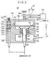
- FIG. 2 shows in cross section each of the electropneumatic transducer units 30a, 30b. Since the electropneumatic transducer units 30a, 30b are identical in structure to each other, they will be referred to collectively as an electropneumatic transducer unit 30. Though parts of the electropneumatic transducer units 30a, 30b are denoted by reference numerals with suffixes "a", "b” in FIG. 1, these suffixes "a”, “b” will be omitted if the electropneumatic transducer unit 30 is described.
- the electropneumatic transducer unit 30 shown in FIG. 2 is disclosed in Japanese laid-open patent publication No. 7-4401. The structure and operation of the electropneumatic transducer unit 30 will be described below.
- the electropneumatic transducer unit 30 comprises a nozzle flapper mechanism 32 and a valve mechanism 122.
- the valve mechanism 122 comprises a housing 126 having a first chamber 130 and a second chamber 132 which are defined therein and communicate with each other through a hole 128.
- a diaphragm 134 is disposed in the first chamber 130, dividing the first chamber 130 into a lower compartment and an upper compartment which serves as a nozzle back pressure chamber 136.
- the nozzle back pressure chamber 136 communicates with a supply passage 138 defined in the housing 126 and connected to a compressed air supply (not shown).
- the supply passage 138 accommodates therein a pressure reducing valve 140 and a fixed restriction 141.
- the pressure reducing valve 140 has a knob 142 threaded in the housing 126, a piston 144 slidably disposed in the supply passage 138, and a first spring 146 acting on the piston 144 and connected to the knob 142.
- the knob 142 is manually turned, the bias of the first spring 146 is adjusted.
- a valve body 152 which can be seated on a valve seat 148 is also disposed in the supply passage 138.
- a second spring 150 is interposed between the piston 144 and the valve seat 148.
- the valve body 152 is held against a shank of the piston 144 by a third spring 154 which is disposed in the supply passage 138 beneath the valve seat 148.
- the piston 144 has a cross-sectional area greater than the cross-sectional area of the valve body 152.
- the piston 144 is urged upwardly, and the valve body 152 biased by the third spring 154 is also displaced upwardly until it is seated on the valve seat 148, disconnecting the nozzle back pressure chamber 136 from the compressed air supply. If the pneumatic pressure in the nozzle back pressure chamber 136 is lower than the pneumatic pressure of the compressed air supply, the valve body 152 is unseated off the valve seat 148 under the bias of the first spring 146, bringing the nozzle back pressure chamber 136 into pneumatic communication with the compressed air supply.
- a valve assembly 156 disposed in the first chamber 130 and the second chamber 132 comprises a flange 158 positioned in the lower compartment of the first chamber 130 and a cylindrical rod (valve body) 60 extending downwardly from the flange 158 through the hole 128 into the second chamber 132 and axially movable in the hole 128.
- the flange 158 is held against the diaphragm 134 under the bias of a spring 162.
- the cylindrical rod 60 is seated on or unseated off a valve seat 164 at the bottom of the second chamber 132.
- a supply passage 166 communicates with the second chamber 132 through the valve seat 164, and an exhaust passage 168 also communicates with the second chamber 132 through a side wall thereof. Therefore, pneumatic communication between the supply passage 166 and the exhaust passage 168 can be controlled by the cylindrical rod 60 because the cylindrical rod 60 closes the supply passage 166 when seated on the valve seat 164 and opens the supply passage 166 when unseated off the valve seat 164.
- the nozzle flapper mechanism 32 comprises a nozzle 172 communicating with the nozzle back pressure chamber 136, a flapper 174 held against a distal end of the nozzle 172, a support 176 by which the flapper 174 is displaceably supported, a bimorph piezoelectric element 180 mounted on the support 176 and spaced a distance from a projection 178 on a lower surface of the flapper 174, and a spring 182 which normally urges the flapper 174 toward the nozzle 172.
- the bimorph piezoelectric element 180 is bent toward the flapper 174 when supplied with a positive voltage from the microcomputer 16, and is bent away from the flapper 174 when supplied with a negative voltage from the microcomputer 16.
- the bimorph piezoelectric element 180 when a positive pulse is applied from the microcomputer 16 to the bimorph piezoelectric element 180, the bimorph piezoelectric element 180 is bent upwardly into contact with the projection 178 and presses the flapper 174 upwardly, as shown in FIG. 3. Therefore, the flapper 174 is spaced from the nozzle 172 against the bias of the spring 182. Since the nozzle 172 is opened, the pneumatic pressure in the nozzle back pressure chamber 136 is lowered, allowing the diaphragm 134 to be displaced upwardly in the direction indicated by the arrow Z1. The valve assembly 156 is also displaced in the direction indicated by the arrow Z1 under the bias of the spring 162 acting on the flange 158. As a result, the cylindrical rod 60 is unseated off the valve seat 164, allowing pneumatic communication between the supply passage 166 and the exhaust passage 168.
- the bimorph piezoelectric element 180 When a negative pulse is applied from the microcomputer 16 to the bimorph piezoelectric element 180, the bimorph piezoelectric element 180 is spaced from the projection 178, and the flapper 174 is brought into abutment against the nozzle 172 under the bias of the spring 182. Since the nozzle 172 is closed, the pneumatic pressure in the nozzle back pressure chamber 136 is increased, displacing the diaphragm 134 and the flange 158 downwardly in the direction indicated by the arrow Z2 against the bias of the spring 162. As a result, the cylindrical rod 60 is seated on the valve seat 164, cutting off pneumatic communication between the supply passage 166 and the exhaust passage 168.
- the reference signal Sr is changed stepwise from a value "0" to a value "1" corresponding to the desired level.
- the microcomputer 16 supplies an output signal not to actuate the nozzle flapper mechanism 32b of the electropneumatic transducer unit 30b connected to the exhaust port 35. Therefore, the valve body 60b of the electropneumatic transducer unit 30b is in the cut-off position.
- the nozzle flapper mechanism 32a of the electropneumatic transducer unit 30a is actuated by an output signal from the microcomputer 16 according to a PWM (Pulse Width Modulation) process disclosed in Japanese laid-open patent publication No. 7-4401. According to the PWM process, the pulse duration in each cycle is initially wider and subsequently progressively smaller.
- a feedback control process is carried out to move the stem 18 smoothly in the direction indicated by the arrow Z2 and stop the stem 18 exactly at a desired position corresponding to the value "1" of the reference signal Sr.
- the reference signal Sr is changed back stepwise from the value "1" to the value "0".
- the microcomputer 16 inactivates the nozzle flapper mechanism 32a of the electropneumatic transducer unit 30a connected to the inlet port 34, bringing the valve body 60a of the electropneumatic transducer unit 30a into the cut-off position.
- the microcomputer 16 actuates the nozzle flapper mechanism 32b of the electropneumatic transducer unit 30b according to the PWM process.
- a feedback control process is also carried out to move the stem 18 smoothly in the direction indicated by the arrow Z1 and stop the stem 18 exactly at a desired position corresponding to the value "0" of the reference signal Sr.
- FIG. 4 shows in block form a control system arrangement of the automatic pneumatic pressure control apparatus shown in FIG. 1.
- the reference numeral 15 represents the pneumatic device 15 which comprises the electropneumatic transducer 12 and the pneumatic actuator 14, the pneumatic device 15 having a transfer function G(p), and the reference numeral 20 represents the position detector 20 for detecting the position of the stem 18 and hence the degree of opening of the regulating valve 40, the position detector 20 being capable of converting the position of the stem 18 as the controlled variable into an electric signal referred to as a feedback signal Sf.
- the functions performed by the microcomputer 16 are shown as various blocks surrounded by the dot-and-dash line in FIG. 4.
- the summing point 200 has its output terminal connected to a first input terminal of an adder 204, a differentiation element (speed element) 206 expressed by an operator "S", a movable terminal 208a of a switch 208.
- the switch 208 has a fixed terminal 108b connected to a second input terminal of the adder 204 through an integration element 210 expressed by an operator "1/S" and a proportional element 212 expressed by an integration proportionality coefficient Ki.
- a speed signal Sv outputted from the differentiation element 206 is supplied to a speed detector 214 and also to a proportional element 216 expressed by a differentiation proportionality coefficient Kd.
- the speed signal Sv is supplied from the proportional element 216 to a third input terminal of the adder 204.
- the differentiation element 206 and the proportional element 216 are connected to each other by a junction that is connected to an input terminal of the speed detector 214.
- the speed signal Sv from the differentiation element 206 is supplied through the junction to the input terminal of the speed detector 214.
- the speed detector 214 compares the speed signal Sv with a predetermined value (also called a "threshold speed signal”, a “reference signal”, a “reference speed”, or a “reference value”) Svr, and supplies a switching signal Sb produced as a binary signal (on/off signal) as the result of comparing the signals Sv, Svr, to a control terminal 208c of the switch 208.
- the switching signal Sb controls the opening and closing the switch 208. Specifically, the switch 208 is opened when the switching signal Sb is of a low level, and closed when the switching signal Sb is of a high level.
- An output signal from the adder 204 i.e., a manipulated variable signal according to a PD control mode or a PID control mode, is supplied through a PWM signal generator 218 to the electropneumatic transducer 12 of the pneumatic device 15.
- electropneumatic transducer units 30a, 30b are alternately actuated, i.e., toggled, by the microcomputer 16.
- a drive signal as a manipulated variable signal is supplied from the PWM signal generator 218 of the microcomputer 16 to the nozzle flapper mechanism 32a, such a drive signal as a manipulated variable signal is not supplied to the nozzle flapper mechanism 32b.
- the valve body 60 (60b) combined with the nozzle flapper mechanism 32b is in the cut-off position as shown in FIG. 2.
- a reference signal Sr which changes stepwise from a low level to a high level is supplied from the input terminal 13 to the summing point 200 at a time t0.
- the switch 208 is open as shown in FIG. 4 with the switching signal Sb being of a low level. Therefore, a PD control mode is carried out by the proportional element 202 and the differentiation element 206, starting to actuate the electropneumatic transducer unit 30a at the time t0.
- valve body 60b Since no drive signal is supplied from the microcomputer 16 to the electropneumatic transducer unit 30b at this time, the valve body 60b is in the cut-off position.
- the nozzle flapper mechanism 32a of the electropneumatic transducer unit 30a is actuated to bring the valve body 60a into the open position.
- the valve body 60a is brought into the open position as follows: When a positive pulse is applied to the bimorph piezoelectric element 180, the nozzle flapper mechanism 32 is actuated to move the flapper 174 away from the nozzle 172, venting the nozzle back pressure chamber 136 to the atmosphere. Strictly, there is a dead time consumed after the positive pulse is applied to the bimorph piezoelectric element 180 until the flapper 174 opens the nozzle 172 against the bias of the spring 182. After the nozzle back pressure chamber 136 is vented to the atmosphere, there is also a dead time consumed until the valve body 142 is unseated off the valve seat 148 under the bias of the first spring 146. Another dead time is consumed until the diaphragm 134 moves in the direction indicated by the arrow Z1.
- valve body 60a is brought into the open position, allowing compressed air to be supplied from the inlet port 34 through the electropneumatic transducer unit 30a and the pipe 33 into the diaphragm chamber 36.
- the speed signal Sv starts to increase from a value "0" as shown in FIG. 5.
- the switching signal Sb outputted from the speed detector 214 changes from a low level to a high level, changing the switch 208 from an open state to a closed state.
- the PD control mode carried out by the proportional element 202 and the differentiation element 206 changes to a PID control mode carried by the carried out by the proportional element 202, the differentiation element 206, and the integration element 210.
- the speed signal Sv is essentially of the value "0" up to the time t2. Therefore, the PD control mode may be replaced with a P control mode from the time t0 to the time t2.
- the switch 208 is not operated. Therefore, the PD control mode changes to the PID control mode when the absolute value
- the switch 208 When the reference signal Sr increases or decreases stepwise at a time t3, the switch 208 is reset to the open state as shown in FIG. 4, whereupon the PID control mode changes back to the PD control mode.
- the switch 208 is open, and the pneumatic device 15 starts being actuated under the P control mode or the PD control mode for the dead time L.
- the value of the speed signal Sv which is a differential of the feedback signal Sf, changes from the value "0".
- the switching signal Sb changes from the low level to the high level, thereby closing the switch 208 at the time t2.
- the pneumatic device 15 is actuated under the PID control mode.
- the automatic pneumatic pressure control apparatus 10 offers the advantage that it can suppress an overshoot or an oscillation in a controlled variable due to the integration of the dead time L.
- the transfer function changes, e.g., if the stem 18 is stopped owing to sliding friction when the output controlled variable happens to fail to change after the step 18 has started to move, e.g., at a time when the movement of the stem 18 becomes slow (a time after the time t2 and near the time t3), then since the I control mode has started at the time t2 before the stem 18 is stopped, the stopped stem 18 can be moved again under the I control mode.
- FIG. 6 shows a control system arrangement of a modified automatic pneumatic pressure control apparatus 10A.
- the feedback signal Sf is supplied to the differentiation element 206, and a proportional element 220 having a transfer gain Kp is inserted between the proportional element 216 and the adder 204.
- the speed signal Sv is produced as an output signal from the differentiation element 206.
- Other details of the automatic pneumatic pressure control apparatus 10A are the same as those of the automatic pneumatic pressure control apparatus 10 shown in FIG. 4.
- FIG. 7 shows an automatic pneumatic pressure control apparatus 10B according to another embodiment of the present invention.
- the automatic pneumatic pressure control apparatus 10B differs from the automatic pneumatic pressure control apparatus 10 shown in FIG. 1 in that the pneumatic actuator 14 is replaced with a pneumatic tank 301, the pneumatic pressure in the pneumatic tank 301 is measured by a pressure gage 302, and an electric output signal from the pressure gage 302 is supplied as a feedback signal Sf to the microcomputer 16.
- the automatic pneumatic pressure control apparatus 10B has a control system arrangement which is the same as those shown in FIGS. 4 and 6, and can be operated with different proportionality coefficients, different proportional gains, or a different reference value Svr.
- the P control mode or the PD control mode switches to the PID control mode. If the principles of the invention are applied to a pneumatic device which suffers a dead time at the start of operation, then the pneumatic device is prevented from suffering an overshoot or an oscillation.
- the present invention can flexibly handle a change in the signal transfer characteristics of the automatic pneumatic pressure control apparatus.
- the P control mode or the PD control mode switches to the PID control mode upon detection of a change in the differential of the output controlled variable. Therefore, if the transfer function changes, e.g., if the output control variable of a pneumatic device having a dead time happens to fail to change due to, for example, the stoppage of a valve body owing to sliding friction or the shutdown of an actuator, then since the I control mode has started before the valve body or the actuator is stopped, the stopped the valve body or the actuator can be moved again under the I control mode.
Landscapes
- Physics & Mathematics (AREA)
- Engineering & Computer Science (AREA)
- Fluid Mechanics (AREA)
- General Physics & Mathematics (AREA)
- Automation & Control Theory (AREA)
- Mechanical Engineering (AREA)
- General Engineering & Computer Science (AREA)
- Control Of Fluid Pressure (AREA)
- Supply Devices, Intensifiers, Converters, And Telemotors (AREA)
- Feedback Control In General (AREA)
Applications Claiming Priority (3)
| Application Number | Priority Date | Filing Date | Title |
|---|---|---|---|
| JP113277/97 | 1997-05-01 | ||
| JP9113277A JPH10306801A (ja) | 1997-05-01 | 1997-05-01 | 自動制御空気圧装置の制御方法 |
| JP11327797 | 1997-05-01 |
Publications (2)
| Publication Number | Publication Date |
|---|---|
| EP0875811A2 true EP0875811A2 (de) | 1998-11-04 |
| EP0875811A3 EP0875811A3 (de) | 2000-10-04 |
Family
ID=14608105
Family Applications (1)
| Application Number | Title | Priority Date | Filing Date |
|---|---|---|---|
| EP98108081A Withdrawn EP0875811A3 (de) | 1997-05-01 | 1998-05-04 | Automatische Kontrolleinrichtung für pneumatischen Druck und zugehöriges Steuerverfahren |
Country Status (3)
| Country | Link |
|---|---|
| US (1) | US6148837A (de) |
| EP (1) | EP0875811A3 (de) |
| JP (1) | JPH10306801A (de) |
Cited By (7)
| Publication number | Priority date | Publication date | Assignee | Title |
|---|---|---|---|---|
| WO2000028389A1 (de) * | 1998-11-10 | 2000-05-18 | Siemens Aktiengesellschaft | Einrichtung zur regelung der temperatur eines technischen prozesses |
| WO2002059487A3 (en) * | 2001-01-25 | 2002-11-14 | Fisher Controls Int | Method and apparatus for multiple-input-multiple-output of a valve/actuator plant |
| FR2825484A1 (fr) * | 2001-06-01 | 2002-12-06 | Draeger Medical Ag | Soupape |
| CN102170287A (zh) * | 2010-12-23 | 2011-08-31 | 西安航空动力控制科技有限公司 | 一种对基于高速开关阀的位置伺服系统的控制方法 |
| CN108319305A (zh) * | 2018-02-05 | 2018-07-24 | 北京卫星环境工程研究所 | 航天器包装箱自动配气系统 |
| WO2023079164A1 (de) * | 2021-11-08 | 2023-05-11 | Samson Aktiengesellschaft | Verfahren zur steuerung eines reglers |
| KR102881040B1 (ko) * | 2024-10-07 | 2025-11-06 | 엘에스이 주식회사 | 학습형 반도체 공정 배기 제어 장치 및 방법 |
Families Citing this family (8)
| Publication number | Priority date | Publication date | Assignee | Title |
|---|---|---|---|---|
| US6247678B1 (en) * | 1999-11-01 | 2001-06-19 | Swagelok Company | Shape memory alloy actuated fluid control valve |
| US6286532B1 (en) * | 2000-05-13 | 2001-09-11 | Ford Global Technologies, Inc. | Control system and method for controlling valve |
| US6814096B2 (en) * | 2000-12-15 | 2004-11-09 | Nor-Cal Products, Inc. | Pressure controller and method |
| US20030226987A1 (en) * | 2002-06-06 | 2003-12-11 | Gallmeyer Christopher F. | Method and apparatus for seat detection and soft seating in a piezoelectric device actuated valve system |
| US6772784B1 (en) | 2003-04-11 | 2004-08-10 | Mac Valves, Inc. | Proportional pressure regulator having positive and negative pressure delivery capability |
| JP5953261B2 (ja) * | 2013-04-30 | 2016-07-20 | Ckd株式会社 | 電空レギュレータ |
| DE102015007424A1 (de) * | 2015-06-09 | 2016-12-15 | Hydac Fluidtechnik Gmbh | Druckregelvorrichtung |
| KR102200529B1 (ko) * | 2018-12-24 | 2021-01-11 | 국방과학연구소 | 유도탄의 안정성과 신뢰성 향상을 위한 유압구동기의 서보밸브 옵셋 보정 방법 |
Family Cites Families (15)
| Publication number | Priority date | Publication date | Assignee | Title |
|---|---|---|---|---|
| US3699989A (en) * | 1970-06-18 | 1972-10-24 | Lummus Co | Feedback control apparatus |
| FR2384292A1 (fr) * | 1977-03-15 | 1978-10-13 | Alsthom Atlantique | Procede de regulation utilisant une voie integrale |
| JPS55143604A (en) * | 1979-04-25 | 1980-11-10 | Hitachi Ltd | Separate control system for manipulated variable |
| JPS6160108A (ja) * | 1984-08-31 | 1986-03-27 | Akai Electric Co Ltd | サ−ボ機構の応答速度制御回路 |
| US4638837A (en) * | 1984-11-13 | 1987-01-27 | Allied Corporation | Electro/pneumatic proportional valve |
| JPS63216113A (ja) * | 1987-03-04 | 1988-09-08 | Sanyo Electric Co Ltd | デジタルサ−ボ装置 |
| JPH0298701A (ja) * | 1988-10-05 | 1990-04-11 | Toshiba Corp | 制御装置 |
| JP3196177B2 (ja) * | 1991-04-15 | 2001-08-06 | 横河電機株式会社 | 電空ポジショナ |
| JP3124602B2 (ja) * | 1991-12-27 | 2001-01-15 | 横河電機株式会社 | サーボモータ位置制御装置 |
| US5335165A (en) * | 1992-05-27 | 1994-08-02 | The Foxboro Company | Method and apparatus for adaptive deadtime process control |
| US5549137A (en) * | 1993-08-25 | 1996-08-27 | Rosemount Inc. | Valve positioner with pressure feedback, dynamic correction and diagnostics |
| US5532925A (en) * | 1994-08-12 | 1996-07-02 | Fisher Controls International, Inc. | Current-to-pressure transducer with selectable, adjustable input filter |
| US5493488A (en) * | 1994-12-05 | 1996-02-20 | Moore Industries International, Inc. | Electro-pneumatic control system and PID control circuit |
| US5526838A (en) * | 1995-01-12 | 1996-06-18 | Mac Valves, Inc. | Method and valve assembly for controlling a pilot signal |
| JPH0949502A (ja) * | 1995-08-08 | 1997-02-18 | Yamatake Honeywell Co Ltd | バルブポジショナ及び電空変換器 |
-
1997
- 1997-05-01 JP JP9113277A patent/JPH10306801A/ja active Pending
-
1998
- 1998-04-30 US US09/069,986 patent/US6148837A/en not_active Expired - Fee Related
- 1998-05-04 EP EP98108081A patent/EP0875811A3/de not_active Withdrawn
Cited By (8)
| Publication number | Priority date | Publication date | Assignee | Title |
|---|---|---|---|---|
| WO2000028389A1 (de) * | 1998-11-10 | 2000-05-18 | Siemens Aktiengesellschaft | Einrichtung zur regelung der temperatur eines technischen prozesses |
| WO2002059487A3 (en) * | 2001-01-25 | 2002-11-14 | Fisher Controls Int | Method and apparatus for multiple-input-multiple-output of a valve/actuator plant |
| FR2825484A1 (fr) * | 2001-06-01 | 2002-12-06 | Draeger Medical Ag | Soupape |
| CN102170287A (zh) * | 2010-12-23 | 2011-08-31 | 西安航空动力控制科技有限公司 | 一种对基于高速开关阀的位置伺服系统的控制方法 |
| CN102170287B (zh) * | 2010-12-23 | 2014-03-12 | 西安航空动力控制科技有限公司 | 一种对基于高速开关阀的位置伺服系统的控制方法 |
| CN108319305A (zh) * | 2018-02-05 | 2018-07-24 | 北京卫星环境工程研究所 | 航天器包装箱自动配气系统 |
| WO2023079164A1 (de) * | 2021-11-08 | 2023-05-11 | Samson Aktiengesellschaft | Verfahren zur steuerung eines reglers |
| KR102881040B1 (ko) * | 2024-10-07 | 2025-11-06 | 엘에스이 주식회사 | 학습형 반도체 공정 배기 제어 장치 및 방법 |
Also Published As
| Publication number | Publication date |
|---|---|
| EP0875811A3 (de) | 2000-10-04 |
| US6148837A (en) | 2000-11-21 |
| JPH10306801A (ja) | 1998-11-17 |
Similar Documents
| Publication | Publication Date | Title |
|---|---|---|
| US6171066B1 (en) | Automatic pneumatic pressure control apparatus and method of controlling same | |
| US6148837A (en) | Automatic pneumatic pressure control apparatus and method of controlling same | |
| EP0827056B1 (de) | Vorrichtung und Methode zur Positionsregelung des Steuerkolbens eines Ventils mit innerer Regelschleife. | |
| US4550747A (en) | Digital fluid pressure flow rate and position control system | |
| US4080110A (en) | Control system for variable capacity gas compressor | |
| KR100604106B1 (ko) | 진공 압력 제어 시스템 | |
| CN100580601C (zh) | 真空压力控制系统 | |
| US4467775A (en) | Method and apparatus for controlling recirculated quantities of exhaust gas in internal combustion engines | |
| US5159812A (en) | Circuitry for controlling control coils of servo devices in a hydraulic system | |
| US6244831B1 (en) | Control device for variable displacement pump | |
| JPH0750418B2 (ja) | 空気圧レギユレ−タ | |
| EP0722134A1 (de) | Methode und Ventilanordnung zur Regelung eines Pilotsignals | |
| JPH03219180A (ja) | 励磁電流制御装置を備えたマグネツト弁 | |
| JP2004319413A (ja) | 燃料電池システムのガス減圧装置 | |
| EP0722135B1 (de) | Methode und Ventilanordnung zur Regelung eines Pilotsignals | |
| JP3533453B2 (ja) | バランス型減圧弁及び給水装置 | |
| JP4369202B2 (ja) | 流体レギュレータ | |
| US12152613B2 (en) | Fluid pressure control device | |
| US4781208A (en) | Device for regulating the concentration of cream in a centrifuge for separating milk | |
| JP2004319412A (ja) | 燃料電池システムのガス減圧装置 | |
| CN212177541U (zh) | 空气功率放大器和一种装置 | |
| JP2617330B2 (ja) | 圧縮機の運転制御方法 | |
| JPH08270604A (ja) | パイロットリレー | |
| JP2880481B2 (ja) | 可変容量形ポンプの制御装置 | |
| JPH07160341A (ja) | 圧力制御弁 |
Legal Events
| Date | Code | Title | Description |
|---|---|---|---|
| PUAI | Public reference made under article 153(3) epc to a published international application that has entered the european phase |
Free format text: ORIGINAL CODE: 0009012 |
|
| AK | Designated contracting states |
Kind code of ref document: A2 Designated state(s): DE GB SE |
|
| AX | Request for extension of the european patent |
Free format text: AL;LT;LV;MK;RO;SI |
|
| PUAL | Search report despatched |
Free format text: ORIGINAL CODE: 0009013 |
|
| AK | Designated contracting states |
Kind code of ref document: A3 Designated state(s): AT BE CH CY DE DK ES FI FR GB GR IE IT LI LU MC NL PT SE |
|
| AX | Request for extension of the european patent |
Free format text: AL;LT;LV;MK;RO;SI |
|
| RIC1 | Information provided on ipc code assigned before grant |
Free format text: 7G 05D 16/20 A, 7F 15B 5/00 B, 7G 05B 11/42 B |
|
| 17P | Request for examination filed |
Effective date: 20010112 |
|
| AKX | Designation fees paid |
Free format text: DE GB SE |
|
| STAA | Information on the status of an ep patent application or granted ep patent |
Free format text: STATUS: THE APPLICATION IS DEEMED TO BE WITHDRAWN |
|
| 18D | Application deemed to be withdrawn |
Effective date: 20021203 |