EP0874681B1 - Vorrichtung zur reinigung von rauchgas - Google Patents
Vorrichtung zur reinigung von rauchgas Download PDFInfo
- Publication number
- EP0874681B1 EP0874681B1 EP96934359A EP96934359A EP0874681B1 EP 0874681 B1 EP0874681 B1 EP 0874681B1 EP 96934359 A EP96934359 A EP 96934359A EP 96934359 A EP96934359 A EP 96934359A EP 0874681 B1 EP0874681 B1 EP 0874681B1
- Authority
- EP
- European Patent Office
- Prior art keywords
- container
- absorbent
- adsorbent
- gas
- shafts
- Prior art date
- Legal status (The legal status is an assumption and is not a legal conclusion. Google has not performed a legal analysis and makes no representation as to the accuracy of the status listed.)
- Expired - Lifetime
Links
- 239000000779 smoke Substances 0.000 title abstract 3
- 238000000746 purification Methods 0.000 title 1
- 239000003463 adsorbent Substances 0.000 claims abstract description 131
- 239000002250 absorbent Substances 0.000 claims abstract description 121
- 230000002745 absorbent Effects 0.000 claims abstract description 121
- 239000007789 gas Substances 0.000 claims abstract description 78
- 238000004140 cleaning Methods 0.000 claims description 33
- 239000003546 flue gas Substances 0.000 claims description 19
- UGFAIRIUMAVXCW-UHFFFAOYSA-N Carbon monoxide Chemical compound [O+]#[C-] UGFAIRIUMAVXCW-UHFFFAOYSA-N 0.000 claims description 18
- XLYOFNOQVPJJNP-UHFFFAOYSA-N water Substances O XLYOFNOQVPJJNP-UHFFFAOYSA-N 0.000 claims description 18
- 239000000203 mixture Substances 0.000 claims description 8
- AXCZMVOFGPJBDE-UHFFFAOYSA-L calcium dihydroxide Chemical compound [OH-].[OH-].[Ca+2] AXCZMVOFGPJBDE-UHFFFAOYSA-L 0.000 abstract description 4
- 239000000920 calcium hydroxide Substances 0.000 abstract description 4
- 235000011116 calcium hydroxide Nutrition 0.000 abstract description 4
- 229910001861 calcium hydroxide Inorganic materials 0.000 abstract description 4
- 239000000126 substance Substances 0.000 abstract description 3
- 239000002245 particle Substances 0.000 description 27
- 230000008901 benefit Effects 0.000 description 17
- 239000010410 layer Substances 0.000 description 16
- 238000000034 method Methods 0.000 description 10
- 239000007787 solid Substances 0.000 description 9
- ODINCKMPIJJUCX-UHFFFAOYSA-N Calcium oxide Chemical compound [Ca]=O ODINCKMPIJJUCX-UHFFFAOYSA-N 0.000 description 8
- 230000015572 biosynthetic process Effects 0.000 description 6
- 239000003344 environmental pollutant Substances 0.000 description 6
- 231100000719 pollutant Toxicity 0.000 description 6
- 230000008859 change Effects 0.000 description 5
- 239000000292 calcium oxide Substances 0.000 description 4
- 235000012255 calcium oxide Nutrition 0.000 description 4
- 238000001035 drying Methods 0.000 description 4
- 239000000428 dust Substances 0.000 description 4
- 230000000694 effects Effects 0.000 description 4
- 230000006872 improvement Effects 0.000 description 4
- 238000002156 mixing Methods 0.000 description 4
- 230000008569 process Effects 0.000 description 4
- 239000000376 reactant Substances 0.000 description 4
- 235000008733 Citrus aurantifolia Nutrition 0.000 description 3
- 235000011941 Tilia x europaea Nutrition 0.000 description 3
- 238000010521 absorption reaction Methods 0.000 description 3
- 230000009471 action Effects 0.000 description 3
- 239000000378 calcium silicate Substances 0.000 description 3
- 229910052918 calcium silicate Inorganic materials 0.000 description 3
- OYACROKNLOSFPA-UHFFFAOYSA-N calcium;dioxido(oxo)silane Chemical compound [Ca+2].[O-][Si]([O-])=O OYACROKNLOSFPA-UHFFFAOYSA-N 0.000 description 3
- 238000006243 chemical reaction Methods 0.000 description 3
- 238000010276 construction Methods 0.000 description 3
- 230000005484 gravity Effects 0.000 description 3
- 239000004571 lime Substances 0.000 description 3
- 239000008267 milk Substances 0.000 description 3
- 210000004080 milk Anatomy 0.000 description 3
- 235000013336 milk Nutrition 0.000 description 3
- 238000001179 sorption measurement Methods 0.000 description 3
- 241000196324 Embryophyta Species 0.000 description 2
- 241000237858 Gastropoda Species 0.000 description 2
- 239000011260 aqueous acid Substances 0.000 description 2
- OSGAYBCDTDRGGQ-UHFFFAOYSA-L calcium sulfate Chemical compound [Ca+2].[O-]S([O-])(=O)=O OSGAYBCDTDRGGQ-UHFFFAOYSA-L 0.000 description 2
- 230000001914 calming effect Effects 0.000 description 2
- 239000007795 chemical reaction product Substances 0.000 description 2
- 239000004744 fabric Substances 0.000 description 2
- 230000006870 function Effects 0.000 description 2
- 238000011086 high cleaning Methods 0.000 description 2
- 239000000463 material Substances 0.000 description 2
- 230000007420 reactivation Effects 0.000 description 2
- 230000009467 reduction Effects 0.000 description 2
- 230000001105 regulatory effect Effects 0.000 description 2
- 239000002699 waste material Substances 0.000 description 2
- 235000002017 Zea mays subsp mays Nutrition 0.000 description 1
- 241000482268 Zea mays subsp. mays Species 0.000 description 1
- 238000005299 abrasion Methods 0.000 description 1
- 239000002253 acid Substances 0.000 description 1
- 230000002378 acidificating effect Effects 0.000 description 1
- 150000007513 acids Chemical class 0.000 description 1
- 230000000274 adsorptive effect Effects 0.000 description 1
- 239000007864 aqueous solution Substances 0.000 description 1
- 239000007900 aqueous suspension Substances 0.000 description 1
- QVGXLLKOCUKJST-UHFFFAOYSA-N atomic oxygen Chemical compound [O] QVGXLLKOCUKJST-UHFFFAOYSA-N 0.000 description 1
- 238000000889 atomisation Methods 0.000 description 1
- 238000005452 bending Methods 0.000 description 1
- 239000011575 calcium Substances 0.000 description 1
- GBAOBIBJACZTNA-UHFFFAOYSA-L calcium sulfite Chemical compound [Ca+2].[O-]S([O-])=O GBAOBIBJACZTNA-UHFFFAOYSA-L 0.000 description 1
- 235000010261 calcium sulphite Nutrition 0.000 description 1
- 239000003153 chemical reaction reagent Substances 0.000 description 1
- 238000002485 combustion reaction Methods 0.000 description 1
- 230000003247 decreasing effect Effects 0.000 description 1
- 230000006735 deficit Effects 0.000 description 1
- 230000008021 deposition Effects 0.000 description 1
- 238000009826 distribution Methods 0.000 description 1
- 238000005108 dry cleaning Methods 0.000 description 1
- 238000001704 evaporation Methods 0.000 description 1
- 230000008020 evaporation Effects 0.000 description 1
- 235000013305 food Nutrition 0.000 description 1
- 238000010438 heat treatment Methods 0.000 description 1
- 230000001771 impaired effect Effects 0.000 description 1
- 230000002452 interceptive effect Effects 0.000 description 1
- 238000011068 loading method Methods 0.000 description 1
- 238000004519 manufacturing process Methods 0.000 description 1
- 238000005065 mining Methods 0.000 description 1
- 238000011328 necessary treatment Methods 0.000 description 1
- 230000003647 oxidation Effects 0.000 description 1
- 238000007254 oxidation reaction Methods 0.000 description 1
- 239000001301 oxygen Substances 0.000 description 1
- 229910052760 oxygen Inorganic materials 0.000 description 1
- 239000000843 powder Substances 0.000 description 1
- 239000000047 product Substances 0.000 description 1
- 230000008439 repair process Effects 0.000 description 1
- 238000012958 reprocessing Methods 0.000 description 1
- 150000003839 salts Chemical class 0.000 description 1
- 238000000926 separation method Methods 0.000 description 1
- 239000002344 surface layer Substances 0.000 description 1
- 230000001360 synchronised effect Effects 0.000 description 1
- 230000007704 transition Effects 0.000 description 1
- 238000004065 wastewater treatment Methods 0.000 description 1
- 239000003643 water by type Substances 0.000 description 1
Images


Classifications
-
- B—PERFORMING OPERATIONS; TRANSPORTING
- B01—PHYSICAL OR CHEMICAL PROCESSES OR APPARATUS IN GENERAL
- B01D—SEPARATION
- B01D53/00—Separation of gases or vapours; Recovering vapours of volatile solvents from gases; Chemical or biological purification of waste gases, e.g. engine exhaust gases, smoke, fumes, flue gases, aerosols
- B01D53/34—Chemical or biological purification of waste gases
- B01D53/74—General processes for purification of waste gases; Apparatus or devices specially adapted therefor
- B01D53/80—Semi-solid phase processes, i.e. by using slurries
-
- B—PERFORMING OPERATIONS; TRANSPORTING
- B01—PHYSICAL OR CHEMICAL PROCESSES OR APPARATUS IN GENERAL
- B01F—MIXING, e.g. DISSOLVING, EMULSIFYING OR DISPERSING
- B01F27/00—Mixers with rotary stirring devices in fixed receptacles; Kneaders
- B01F27/05—Stirrers
- B01F27/051—Stirrers characterised by their elements, materials or mechanical properties
- B01F27/054—Deformable stirrers, e.g. deformed by a centrifugal force applied during operation
- B01F27/0543—Deformable stirrers, e.g. deformed by a centrifugal force applied during operation the position of the stirring elements depending on the direction of rotation of the stirrer
-
- B—PERFORMING OPERATIONS; TRANSPORTING
- B01—PHYSICAL OR CHEMICAL PROCESSES OR APPARATUS IN GENERAL
- B01D—SEPARATION
- B01D53/00—Separation of gases or vapours; Recovering vapours of volatile solvents from gases; Chemical or biological purification of waste gases, e.g. engine exhaust gases, smoke, fumes, flue gases, aerosols
- B01D53/02—Separation of gases or vapours; Recovering vapours of volatile solvents from gases; Chemical or biological purification of waste gases, e.g. engine exhaust gases, smoke, fumes, flue gases, aerosols by adsorption, e.g. preparative gas chromatography
- B01D53/06—Separation of gases or vapours; Recovering vapours of volatile solvents from gases; Chemical or biological purification of waste gases, e.g. engine exhaust gases, smoke, fumes, flue gases, aerosols by adsorption, e.g. preparative gas chromatography with moving adsorbents, e.g. rotating beds
- B01D53/08—Separation of gases or vapours; Recovering vapours of volatile solvents from gases; Chemical or biological purification of waste gases, e.g. engine exhaust gases, smoke, fumes, flue gases, aerosols by adsorption, e.g. preparative gas chromatography with moving adsorbents, e.g. rotating beds according to the "moving bed" method
-
- B—PERFORMING OPERATIONS; TRANSPORTING
- B01—PHYSICAL OR CHEMICAL PROCESSES OR APPARATUS IN GENERAL
- B01D—SEPARATION
- B01D53/00—Separation of gases or vapours; Recovering vapours of volatile solvents from gases; Chemical or biological purification of waste gases, e.g. engine exhaust gases, smoke, fumes, flue gases, aerosols
- B01D53/34—Chemical or biological purification of waste gases
- B01D53/46—Removing components of defined structure
- B01D53/48—Sulfur compounds
- B01D53/50—Sulfur oxides
- B01D53/501—Sulfur oxides by treating the gases with a solution or a suspension of an alkali or earth-alkali or ammonium compound
- B01D53/504—Sulfur oxides by treating the gases with a solution or a suspension of an alkali or earth-alkali or ammonium compound characterised by a specific device
-
- B—PERFORMING OPERATIONS; TRANSPORTING
- B01—PHYSICAL OR CHEMICAL PROCESSES OR APPARATUS IN GENERAL
- B01D—SEPARATION
- B01D53/00—Separation of gases or vapours; Recovering vapours of volatile solvents from gases; Chemical or biological purification of waste gases, e.g. engine exhaust gases, smoke, fumes, flue gases, aerosols
- B01D53/34—Chemical or biological purification of waste gases
- B01D53/46—Removing components of defined structure
- B01D53/48—Sulfur compounds
- B01D53/50—Sulfur oxides
- B01D53/508—Sulfur oxides by treating the gases with solids
-
- B—PERFORMING OPERATIONS; TRANSPORTING
- B01—PHYSICAL OR CHEMICAL PROCESSES OR APPARATUS IN GENERAL
- B01D—SEPARATION
- B01D53/00—Separation of gases or vapours; Recovering vapours of volatile solvents from gases; Chemical or biological purification of waste gases, e.g. engine exhaust gases, smoke, fumes, flue gases, aerosols
- B01D53/34—Chemical or biological purification of waste gases
- B01D53/74—General processes for purification of waste gases; Apparatus or devices specially adapted therefor
- B01D53/81—Solid phase processes
- B01D53/83—Solid phase processes with moving reactants
-
- B—PERFORMING OPERATIONS; TRANSPORTING
- B01—PHYSICAL OR CHEMICAL PROCESSES OR APPARATUS IN GENERAL
- B01F—MIXING, e.g. DISSOLVING, EMULSIFYING OR DISPERSING
- B01F27/00—Mixers with rotary stirring devices in fixed receptacles; Kneaders
- B01F27/05—Stirrers
- B01F27/11—Stirrers characterised by the configuration of the stirrers
- B01F27/118—Stirrers in the form of brushes, sieves, grids, chains or springs
-
- B—PERFORMING OPERATIONS; TRANSPORTING
- B01—PHYSICAL OR CHEMICAL PROCESSES OR APPARATUS IN GENERAL
- B01F—MIXING, e.g. DISSOLVING, EMULSIFYING OR DISPERSING
- B01F27/00—Mixers with rotary stirring devices in fixed receptacles; Kneaders
- B01F27/80—Mixers with rotary stirring devices in fixed receptacles; Kneaders with stirrers rotating about a substantially vertical axis
- B01F27/85—Mixers with rotary stirring devices in fixed receptacles; Kneaders with stirrers rotating about a substantially vertical axis with two or more stirrers on separate shafts
-
- B—PERFORMING OPERATIONS; TRANSPORTING
- B01—PHYSICAL OR CHEMICAL PROCESSES OR APPARATUS IN GENERAL
- B01J—CHEMICAL OR PHYSICAL PROCESSES, e.g. CATALYSIS OR COLLOID CHEMISTRY; THEIR RELEVANT APPARATUS
- B01J19/00—Chemical, physical or physico-chemical processes in general; Their relevant apparatus
- B01J19/18—Stationary reactors having moving elements inside
-
- B—PERFORMING OPERATIONS; TRANSPORTING
- B01—PHYSICAL OR CHEMICAL PROCESSES OR APPARATUS IN GENERAL
- B01D—SEPARATION
- B01D2258/00—Sources of waste gases
- B01D2258/02—Other waste gases
- B01D2258/0283—Flue gases
- B01D2258/0291—Flue gases from waste incineration plants
-
- B—PERFORMING OPERATIONS; TRANSPORTING
- B01—PHYSICAL OR CHEMICAL PROCESSES OR APPARATUS IN GENERAL
- B01D—SEPARATION
- B01D53/00—Separation of gases or vapours; Recovering vapours of volatile solvents from gases; Chemical or biological purification of waste gases, e.g. engine exhaust gases, smoke, fumes, flue gases, aerosols
- B01D53/02—Separation of gases or vapours; Recovering vapours of volatile solvents from gases; Chemical or biological purification of waste gases, e.g. engine exhaust gases, smoke, fumes, flue gases, aerosols by adsorption, e.g. preparative gas chromatography
- B01D53/04—Separation of gases or vapours; Recovering vapours of volatile solvents from gases; Chemical or biological purification of waste gases, e.g. engine exhaust gases, smoke, fumes, flue gases, aerosols by adsorption, e.g. preparative gas chromatography with stationary adsorbents
- B01D53/0407—Constructional details of adsorbing systems
- B01D53/0446—Means for feeding or distributing gases
-
- B—PERFORMING OPERATIONS; TRANSPORTING
- B01—PHYSICAL OR CHEMICAL PROCESSES OR APPARATUS IN GENERAL
- B01J—CHEMICAL OR PHYSICAL PROCESSES, e.g. CATALYSIS OR COLLOID CHEMISTRY; THEIR RELEVANT APPARATUS
- B01J2208/00—Processes carried out in the presence of solid particles; Reactors therefor
- B01J2208/00008—Controlling the process
- B01J2208/00017—Controlling the temperature
- B01J2208/0053—Controlling multiple zones along the direction of flow, e.g. pre-heating and after-cooling
-
- B—PERFORMING OPERATIONS; TRANSPORTING
- B01—PHYSICAL OR CHEMICAL PROCESSES OR APPARATUS IN GENERAL
- B01J—CHEMICAL OR PHYSICAL PROCESSES, e.g. CATALYSIS OR COLLOID CHEMISTRY; THEIR RELEVANT APPARATUS
- B01J2208/00—Processes carried out in the presence of solid particles; Reactors therefor
- B01J2208/00008—Controlling the process
- B01J2208/00548—Flow
-
- B—PERFORMING OPERATIONS; TRANSPORTING
- B01—PHYSICAL OR CHEMICAL PROCESSES OR APPARATUS IN GENERAL
- B01J—CHEMICAL OR PHYSICAL PROCESSES, e.g. CATALYSIS OR COLLOID CHEMISTRY; THEIR RELEVANT APPARATUS
- B01J2219/00—Chemical, physical or physico-chemical processes in general; Their relevant apparatus
- B01J2219/00049—Controlling or regulating processes
- B01J2219/00051—Controlling the temperature
- B01J2219/00159—Controlling the temperature controlling multiple zones along the direction of flow, e.g. pre-heating and after-cooling
-
- B—PERFORMING OPERATIONS; TRANSPORTING
- B01—PHYSICAL OR CHEMICAL PROCESSES OR APPARATUS IN GENERAL
- B01J—CHEMICAL OR PHYSICAL PROCESSES, e.g. CATALYSIS OR COLLOID CHEMISTRY; THEIR RELEVANT APPARATUS
- B01J2219/00—Chemical, physical or physico-chemical processes in general; Their relevant apparatus
- B01J2219/00049—Controlling or regulating processes
- B01J2219/00164—Controlling or regulating processes controlling the flow
-
- B—PERFORMING OPERATIONS; TRANSPORTING
- B01—PHYSICAL OR CHEMICAL PROCESSES OR APPARATUS IN GENERAL
- B01J—CHEMICAL OR PHYSICAL PROCESSES, e.g. CATALYSIS OR COLLOID CHEMISTRY; THEIR RELEVANT APPARATUS
- B01J2219/00—Chemical, physical or physico-chemical processes in general; Their relevant apparatus
- B01J2219/18—Details relating to the spatial orientation of the reactor
- B01J2219/182—Details relating to the spatial orientation of the reactor horizontal
-
- B—PERFORMING OPERATIONS; TRANSPORTING
- B01—PHYSICAL OR CHEMICAL PROCESSES OR APPARATUS IN GENERAL
- B01J—CHEMICAL OR PHYSICAL PROCESSES, e.g. CATALYSIS OR COLLOID CHEMISTRY; THEIR RELEVANT APPARATUS
- B01J2219/00—Chemical, physical or physico-chemical processes in general; Their relevant apparatus
- B01J2219/18—Details relating to the spatial orientation of the reactor
- B01J2219/185—Details relating to the spatial orientation of the reactor vertical
-
- Y—GENERAL TAGGING OF NEW TECHNOLOGICAL DEVELOPMENTS; GENERAL TAGGING OF CROSS-SECTIONAL TECHNOLOGIES SPANNING OVER SEVERAL SECTIONS OF THE IPC; TECHNICAL SUBJECTS COVERED BY FORMER USPC CROSS-REFERENCE ART COLLECTIONS [XRACs] AND DIGESTS
- Y10—TECHNICAL SUBJECTS COVERED BY FORMER USPC
- Y10S—TECHNICAL SUBJECTS COVERED BY FORMER USPC CROSS-REFERENCE ART COLLECTIONS [XRACs] AND DIGESTS
- Y10S366/00—Agitating
- Y10S366/607—Chain-type stirrer
Definitions
- the invention relates to a device for cleaning Flue gas with the features of the preamble of the claim 1.
- EP-A-0 104 335 discloses that the reaction between those contained in the raw gas Pollutants and the ad / absorbent can be improved if additional water is added. This happens in the way that in a first stage dry, powdery reactant blown in and in a second stage pure water or an aqueous solution or suspension of a reactant is injected. Through the water added in the second stage can reactivate particles of the reactant can be achieved. By adding water, this can be done Reagent can be better used.
- the disadvantage here is that the amount of water added is so small must be kept that even at a relatively low starting temperature the exhaust gas does not fall below the dew point. Becomes Failure to do so may result from the aggressive being formed aqueous acids can damage the system.
- EP-B-0 203 430 a method and a device for cleaning Flue gas is proposed, the ratio of the residence time an ad / absorbent fed to the reactor at the residence time of the Flue gas is regulated and / or controlled in the reactor, that moving in the reactor relative to the reactor vessel Internals, for example in the form of a rotating screw, are provided.
- This worm can run at a speed of approx. 0.5 to 120 U / min are driven, the ad / absorbent partially deposited on the surfaces of the snail, however again and again of the flue gases to be cleaned or of additional blown compressed air is whirled up.
- the dwell time of the heavier ad / absorbent particles controlled relative to the residence time of the gas in the reactor or be managed.
- a disadvantage of this device or this method is however, that with increasing reactor uptime both on the inside of the container as well as on the surface of the moving internals a hard layer, which is formed by the solids in the reactor. This extremely hard and tough layer can practically only with mining Funds are reduced.
- EP-A-0 342 559 describes a device for Separation of dust and / or acidic pollutants from gases and a link head for such a device are known, a in the lower and upper area of the reactor vessel a vertical axis rotatably driven link head arranged is. There are several chain-shaped on the link head or on its hub Arranged arranged when the rotation of the Extend the link head almost to the wall. This can avoid crusting on the wall in the area of the limbs become. In the reactor vessel, the gas flow is controlled by means of a corresponding Guide walls deflected several times.
- the present Invention the object of an apparatus for cleaning of flue gas, especially for dry cleaning of flue gas, to create, which has a high cleaning efficiency, at the substantial impairment of function due to deposits on the inside of the container or on moving Parts are avoided and which are flexible at the same time Construction allows.
- the invention is based on the knowledge that by providing flexible swirling elements, which of the movable internals are included, the formation of interfering layers of is avoided in advance or greatly reduced and then by a change in shape of the flexible swirling elements to simple Way can be eliminated.
- the formation of deposits on the flexible interlacing elements can be prevented, for example, that at certain intervals a change in the Movement speed of the swirling elements made is, so that the shape of the flexible elements changes and this may result in thin deposits be blown off.
- the invention thus offers the advantage of an automatic Cleaning both the flexible swirling elements as well the inner wall of the container.
- the flexible swirling elements are rotated with such a speed that the resulting Whirling the raw gas / adsorbent mixture the reaction rate and thus the cleaning efficiency due to the resulting high relative speeds between the ad / absorbent particles and the raw gas is improved.
- the rigid moving components according to EP-B-0 203 430 serve the flexible swirling elements of the invention Device primarily to be sufficient To achieve turbulence in the raw gas / adsorbent mixture.
- Ratio of the residence time of the adsorbent to the residence time of the Gases can be controlled in the reactor.
- the device according to the invention results the advantage of easy removal of the movable Built-in components, since the shafts, for example, are small thanks to flanges Diameter can be attached to the container so that after dismantling a flange, the shaft including the flexible Swirling elements can be removed. Because of the flexibility the swirling elements is only an opening for this relatively small size and thus a flange of small diameter required.
- the flexible swirling elements are along a helix on the circumference of a or several waves arranged. This gives the advantage a flow component that can be generated to a certain extent in Direction of conveyance of the worm resulting from the rotation of the shaft.
- several sections can be on a shaft such screws may be provided, the direction of conveyance also can be opposite.
- the flexible swirling elements on one or more shafts each divided into several in the axial direction of the shafts Groups are provided, preferably the groups of each wave in the same axial sections between two perpendicular to the waves lying planes are provided.
- the container can both in the device according to the invention be used lying as well as standing, which makes the device can be adapted very flexibly to an existing space requirement can.
- the container can have a substantially rectangular cross section have, the walls lying parallel to the waves of the container have inner sides, which consist of several partially cylindrical Areas exist. Each wave is preferred provided essentially in the axis of a partial cylinder. This results in an improved swirling of the gas / adsorbent mixture.
- By forming the inner wall in The shape of several part-cylindrical areas is compared to one purely cylindrical structure the danger of a quasi-laminar flow of the mixture avoided.
- Flow guiding elements can be provided or areas of the inner sides be shaped accordingly.
- these flow guide elements in turn as circular cylindrical Walls are formed which are coaxial to the Waves are arranged.
- the adsorbent / absorbent each have at least one feed opening intended.
- mixing the Ad / absorbent with the raw gas also in front of the container Place.
- a collecting device for the ad / absorbent provided, which is preferably a conveyor has, which extends over the entire length of the bottom Area of the container or one adjacent to the gas discharge side extends bottom area. If necessary, the Conveyor partly by means of one or more cover plates be covered.
- the collecting device is preferably designed such that a predetermined part of the adsorbing / absorbing the container in the form of a cycle can be fed again, this in the collecting shaft located ad / absorbent to maintain the Pressure difference between the gas supply side and the gas discharge side of the container. This will prevent gas via the external feed path of the adsorbent / absorbent and the collecting device in the immediate vicinity of the gas discharge opening in the Container arrives without going through the correct "cleaning route" to have.
- the feed opening is on the container of the device according to the invention an ad / absorbent supply device is provided.
- ad / absorbent feeder becomes the required one Amount of ad / absorbent introduced into the container and the part of the Ad / absorbent that is finally disposed of by the collection device for disposal is dissipated, in the form of fresh, unused ad / absorbent replaced.
- the ad / absorbent supply device can be a device for adding water up to a predetermined Moisture content, thereby reactivating the consequent of the last pass through the dried ad / absorbent container is achieved.
- this can lead to reactivation of the already reacted surfaces of the adsorbent / absorbent particles come and on the other hand the water from the ad / absorbent particles due to capillary action also into the interior of the particle sucked so it is due to the sudden heating after entering the container interior to a sudden Evaporation of the water is coming. This will make the particles blown up ("popcorn effect") and thus an enlargement of the adsorbing or absorbing surface reached.
- hydrated lime Ca (OH) 2
- a device for adding lime milk can be provided instead of a device for adding water.
- the required addition of fresh ad / absorbent in the form of dry hydrated lime and the separate addition of water can be replaced by adding lime milk in a single addition.
- this reduces the effort for the ad / absorbent feed device and, on the other hand, there is the advantage that the lime milk to be added can be produced from quicklime (CaO) and water. So only quicklime has to be delivered to the filter system (it is assumed here that water is available on site anyway), the amount of quicklime required being far less than the comparable amount of hydrated lime. This results in a reduction in transportation costs.
- adsorbent Due to the special design of the moving components as flexible Internals that have a high throughput of adsorbent / absorbent enables, can in the device according to the invention as an adsorbent also calcium silicate hydrate (CaSiOH) up to a grain size of 5 mm and more can be used. Calcium silicate hydrate accumulates in this form as waste in the manufacture of gas concrete and thus represents a very inexpensive ad / absorbent. Because of the relatively large particles produced here, the However, use with known devices is not possible or because of the necessary treatment of the calcium silicate hydrate unprofitable.
- CaSiOH calcium silicate hydrate
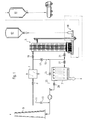
- the overall system shown in Fig. 1 for cleaning Flue gas essentially consists of a precooler 1, which the raw gas to be cleaned in the direction of the arrow via a flap 3 is supplied, as well as from the actual device 5 Cleaning the flue gas, which is a solid separator 7 is connected downstream. The cleaned flue gas is then by means of a fireplace 9 delivered.
- a precooler 1 which the raw gas to be cleaned in the direction of the arrow via a flap 3 is supplied, as well as from the actual device 5
- Cleaning the flue gas which is a solid separator 7 is connected downstream.
- the cleaned flue gas is then by means of a fireplace 9 delivered.
- a parallel connection of several devices 5 the cleaning performance increased or by a series connection of several devices 5 the cleaning of the gases can be improved.
- Fig. 1 The path of the gas through the system in normal operation is shown in Fig. 1 represented by the bold lines and arrows.
- the thin solid lines represent paths that improve operational safety in the event of a fault in one or more components guarantee. So it is with the line 11 and the associated flap 13 around an emergency bypass, with which the entire System bridged and the raw gases fed directly to the chimney 9 can be.
- the device 5 which is shown in Fig. 2a, comprises a Container 31, which the raw gas in the direction of the arrow via a feed opening 33 is supplied.
- the cleaned raw gas is over a discharge opening 35 is discharged in the lower region of the container 31 and the solids separator 7 (FIG. 1), which can be designed, for example, as a fabric filter.
- the container 31 is via an ad / absorbent feed device 37 dry or quasi-dry dusty or powdery adsorbent / absorbent fed.
- the adsorption or absorption of pollutants in the raw gas is improved by the ad / absorbent particles if this one have certain moisture, is in the ad / absorbent feed device 37 water was added while mixing the adsorbent / absorbent, until a predetermined moisture content is reached.
- This can of course automatically in the form of a closed Control loop take place, the moisture content depending on certain parameters, for example the temperature of the supplied Raw gas, can be selected.
- the Moisture content of the adsorbent / absorbent before being fed into the interior of the container 31, for example, up to the limit of the presence a dusty structure can be increased.
- the ad / absorbent However, it is still in dust or powder form before, so that still a high active surface for the Cleaning is available.
- shafts 39 are provided in the example shown, which run parallel to the longitudinal axis of the container.
- the waves are by means of electric motors 41 attached to the top of the container 31 are arranged, driven in rotation.
- the container 31 can have a wall 31a have, the inner wall of several partially cylindrical regions 31b.
- the four waves are then, as shown in Fig. 2b, preferably arranged so that they are each in the Axis of the partially cylindrical regions 31b lie.
- the shafts 39 can with respect their rotational movement are driven synchronized, so that the chains 43 do not collide in the area of the center of the container.
- This synchronization can be used for cleaning purposes can also be lifted at short notice, so that the chains become worn clean each other.
- the chains can, for example be evenly distributed to avoid unbalance or bending of the shafts a symmetrical one Arrangement of chains in a plane perpendicular to the shaft is preferable is. As shown in Fig. 2b, for example 4 chains can be provided in one level.
- the chains 43 can also create different swirl effects be long.
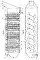
- the chains can, as shown in Fig. 2a, in the axial direction can also be arranged in groups, with zones of high turbulence alternate with calming zones. Especially in the Transition layers then develop high relative speeds between the ad / absorbent particles and the gas.
- a collecting device 45 for the adsorbent / absorbent which, as in FIG. 3 recognizable more clearly, comprises a conveyor 47 which that accumulates on a conveyor chain 49 (partly with Ad / absorbent loaded with pollutants in a collecting shaft 51 feeds.
- the conveyor chain 49 preferably extends over the entire bottom surface of the container 31.
- Conveying device 53 which by means of another Conveyor chain 55 the ad / absorbent again to the ad / absorbent feeder 37 feeds.
- the latter can do this, for example comprise conveyor section 57 designed as a bucket elevator.
- the Conveyor line 57 is also that by means of the solids separator 7 (Fig. 1) deposited dusty product that largely consists of ad / absorbent supplied. This results in a optimal use of the adsorbent / absorbent.
- the ad / absorbent supply device 37 comprises one Feed device 58 for fresh goods, that is to say fresh adsorbent.
- This fresh material feed device can, as in the figures 1 and 2a, the fresh material at the bottom of the Feed conveyor line 57 from an ad / absorbent silo 62 (FIG. 1).
- the supply of fresh food can also at any point between the ad / absorbent feed opening and the ad / absorbent collection device 45.
- the already amount of circulating ad / absorbent Fresh goods can depend on certain parameters, e.g. the too ad / absorbing amount of pollutant, controlled or regulated become.
- One corresponding to the registered and separated quantity Share of the resulting reaction products is from the ad / absorbent cycle from the collecting shaft 51, as shown in FIG. 3, by means of a discharge device 59, for example can comprise a screw conveyor, discharged and the waste silo 61 (Fig. 1) supplied for disposal.
- a discharge device 59 for example can comprise a screw conveyor, discharged and the waste silo 61 (Fig. 1) supplied for disposal.
- the in circulation the amount of ad / absorbent present becomes essentially constant held.
- the device according to the invention not only results in an improvement in the cleaning efficiency with a simple structure of the device, but also an improvement in the utilization of the adsorbent / absorbent by the reactivation in the adsorbent / absorbent supply device.
- Each ad / absorbent particle passes through the container 31 several times and contributes several times to cleaning the gas.
- the ad / absorbent thus remains - with a corresponding total amount of ad / absorbent within the cycle - for a relatively long time in the cycle (two days and more), which additionally has the advantage that the reaction products formed are caused by the residual oxygen present in the gas and by the Moisture can be oxidized.
- the container 31 is the device 5 formed lying, the shafts 39 perpendicular to the longitudinal axis of the container are arranged in the vertical direction.
- the drive of the shafts remains essentially unchanged.
- the horizontal design of the container 31 results however the advantage that the bearing of the shafts, in particular also on the underside, outside the container interior can and thus protects the bearings from aggressive gases are.
- the feed opening 33 for the raw gas initially widens up to the entire cross section of the container 31, whereby achieved a reduction in flow velocity becomes. In this way, the gases to be cleaned remain inside of the container 31, which leads to an increase in the cleaning effect contributes.
- the chains 43 arranged on the shafts 39 are essentially arranged at equidistant axial distances on the shafts and so distributed over the circumference of the shaft that an unbalance is avoided becomes.
- chains should be provided so that in each perpendicular to the shaft Level an unbalance is excluded.
- the shafts 39 are parallel Inner walls of the container in turn with partially cylindrical Sections 31b 'provided, whereby the already above described advantages result.
- Flow guiding elements can be provided which have an undisturbed gas flow prevent in the direction of the gas discharge openings 35.
- the collecting device 45 for the Ad / absorbent provided in the bottom wall of the container 31 is in the range Gas discharge opening 35 in turn the collecting device 45 for the Ad / absorbent provided.
- the presentation of the Circulation for the adsorbent / absorbent dispensed with is the presentation of the Circulation for the adsorbent / absorbent dispensed with.
- the ad / absorbent particles supplied settle again and again on the bottom wall and are whirled up again.
- the ad / absorbent particles from the gas flow towards the gas discharge opening 35 carried along. Since in the rear area of the container 31, i.e. in the Area of the collecting device 45 no more rotating shafts the ad / absorbent particles are already set largely on the conveyor chain of the collecting device 45. Those particles that are still moving in the direction of the gas flow are taken to the gas discharge opening 35, sit down due to gravity from the diagonally upward Formation of the discharge channel over time on the lower one Wall of the discharge channel and slide due to the relative great steepness of this wall down towards the Collecting device 45.
- the collecting device 45 for the Provide the adsorbent / absorbent with a longer conveyor chain which is driven so that the ad / absorbent located on the conveyor chain conveyed towards the end of the container and from there at the bottom of the conveyor chain towards the collecting shaft is promoted.
- This can be achieved that the Concentration of the ad / absorbent particles in the area of the waves 39, which are located above the conveyor chain, opposite the Ad / absorbent concentration in the front area of the container 31 decreased. In this way, the proportion of ad / absorbent particles discharged through the gas through the gas discharge opening 35.
- the horizontal formation of the shafts 39 wind them Chains 43 at low speed of the shafts, for example when Stop the device to the waves, so that an unobstructed Access to the interior of the container 31 is possible. At at higher speeds, however, the chains are unwound due to the centrifugal force, so that even in this embodiment optimal swirling of the gas / adsorbent mixture is ensured.
- Fig. 6 shows a simplified embodiment of the invention also lying container 31.
- the waves 39 are again horizontal and arranged perpendicular to the longitudinal axis of the container 31.
- this embodiment is only one Row of shafts 39 provided, the chains just as well are long that the chains touch each other is avoided. As a result, synchronization can occur the drives for the shafts 39 are dispensed with.
- This can, as shown in Fig. 6a, either be driven so that the top is the conveyor chain moves in the direction of the gas discharge opening 35, so that the ad / absorbent between the bottom of the conveyor chain and the inner wall of the container towards the collecting shaft the device 45 is promoted.
- the conveyor chain can also be driven in opposite directions so that the ad / absorbent that is on the conveyor chain deposits, again and again in the direction of the gas supply opening 33 is moved.
- the speed of the conveyor chain must then, however be chosen larger than the average movement speed the ad / absorbent particles in the gas stream.
Landscapes
- Chemical & Material Sciences (AREA)
- Engineering & Computer Science (AREA)
- Chemical Kinetics & Catalysis (AREA)
- Environmental & Geological Engineering (AREA)
- Analytical Chemistry (AREA)
- General Chemical & Material Sciences (AREA)
- Oil, Petroleum & Natural Gas (AREA)
- Biomedical Technology (AREA)
- Health & Medical Sciences (AREA)
- Organic Chemistry (AREA)
- Treating Waste Gases (AREA)
- Gas Separation By Absorption (AREA)
- Separation Of Gases By Adsorption (AREA)
- Separation Of Particles Using Liquids (AREA)
- Filtering Of Dispersed Particles In Gases (AREA)
- Separating Particles In Gases By Inertia (AREA)
- General Preparation And Processing Of Foods (AREA)
- Incineration Of Waste (AREA)
Priority Applications (1)
| Application Number | Priority Date | Filing Date | Title |
|---|---|---|---|
| EP97109512A EP0800854B1 (de) | 1995-08-18 | 1996-08-19 | Vorrichtung zur Reinigung von Rauchgas |
Applications Claiming Priority (3)
| Application Number | Priority Date | Filing Date | Title |
|---|---|---|---|
| DE19530497 | 1995-08-18 | ||
| DE19530497A DE19530497C1 (de) | 1995-08-18 | 1995-08-18 | Vorrichtung zur Reinigung von Rauchgas |
| PCT/DE1996/001542 WO1997006874A1 (de) | 1995-08-18 | 1996-08-19 | Vorrichtung zur reinigung von rauchgas |
Related Child Applications (2)
| Application Number | Title | Priority Date | Filing Date |
|---|---|---|---|
| EP97109512A Division EP0800854B1 (de) | 1995-08-18 | 1996-08-19 | Vorrichtung zur Reinigung von Rauchgas |
| EP97109512.0 Division-Into | 1997-06-11 |
Publications (2)
| Publication Number | Publication Date |
|---|---|
| EP0874681A1 EP0874681A1 (de) | 1998-11-04 |
| EP0874681B1 true EP0874681B1 (de) | 2000-09-06 |
Family
ID=7769857
Family Applications (2)
| Application Number | Title | Priority Date | Filing Date |
|---|---|---|---|
| EP96934359A Expired - Lifetime EP0874681B1 (de) | 1995-08-18 | 1996-08-19 | Vorrichtung zur reinigung von rauchgas |
| EP97109512A Revoked EP0800854B1 (de) | 1995-08-18 | 1996-08-19 | Vorrichtung zur Reinigung von Rauchgas |
Family Applications After (1)
| Application Number | Title | Priority Date | Filing Date |
|---|---|---|---|
| EP97109512A Revoked EP0800854B1 (de) | 1995-08-18 | 1996-08-19 | Vorrichtung zur Reinigung von Rauchgas |
Country Status (12)
| Country | Link |
|---|---|
| US (1) | US6177052B1 (cs) |
| EP (2) | EP0874681B1 (cs) |
| JP (1) | JP3881380B2 (cs) |
| KR (1) | KR100458387B1 (cs) |
| AT (2) | ATE209953T1 (cs) |
| AU (1) | AU7277696A (cs) |
| CZ (1) | CZ294508B6 (cs) |
| DE (4) | DE19530497C1 (cs) |
| ES (1) | ES2152044T3 (cs) |
| HU (1) | HU223032B1 (cs) |
| PL (1) | PL184000B1 (cs) |
| WO (1) | WO1997006874A1 (cs) |
Cited By (2)
| Publication number | Priority date | Publication date | Assignee | Title |
|---|---|---|---|---|
| DE102006038443B3 (de) * | 2006-08-16 | 2007-09-13 | Andreas Friedl | Vorrichtung zur Reinigung von Rauchgas |
| DE102009043120A1 (de) | 2009-09-25 | 2011-04-07 | Dantherm Filtration Gmbh | Verfahren und Vorrichtung zur Reinigung von Rauch- und Abgasen |
Families Citing this family (14)
| Publication number | Priority date | Publication date | Assignee | Title |
|---|---|---|---|---|
| DE69818269D1 (de) * | 1997-07-19 | 2003-10-23 | Klean Earth Environmental Co I | Verfahren und vorrichtung zum mischen und reagieren von einem pulver mit einer flüssigkeit |
| DE29807889U1 (de) * | 1998-05-02 | 1998-07-30 | ROB Ing. Rudolf Ohlmann Techn.Beratung & Vermittlung, 91459 Markt Erlbach | Einrichtung zum Einbringen eines Adsorptionsmittels in ein Abgas |
| ES2340940T3 (es) * | 2005-04-14 | 2010-06-11 | Luigi Pietro Della Casa | Pulverizador mezclador de rodillos para pulverizar y mezclar fluidos. |
| CN101745308B (zh) * | 2008-12-17 | 2012-08-29 | 贵阳铝镁设计研究院有限公司 | 一种赤泥脱硫塔 |
| US8172448B1 (en) | 2009-09-03 | 2012-05-08 | Astec, Inc. | Method and apparatus for adapting asphalt dryer/mixer to minimize asphalt build-up |
| FR2982175B1 (fr) * | 2011-11-07 | 2015-06-12 | Sita Bioenergies | Installation d'epuration de biogaz, procede de traitement de biogaz et utilisation de machefers pour un tel traitement. |
| CA2937341C (en) | 2015-07-28 | 2023-10-03 | Douglas G. Pullman | Mixing apparatus and system |
| US10414693B2 (en) * | 2017-07-24 | 2019-09-17 | Carmeuse North America | Composition for treatment of flue gas waste products |
| CN107398161A (zh) * | 2017-09-11 | 2017-11-28 | 西安热工研究院有限公司 | 燃煤电站锅炉烟气水分回收及细颗粒物脱除的系统及方法 |
| CN110772967A (zh) * | 2019-11-14 | 2020-02-11 | 西安交通大学 | 一种自适应风量波动的旋转烟气半干法脱硫装置 |
| CN114618291A (zh) * | 2020-12-10 | 2022-06-14 | 西南科技大学 | 生石灰的干法消化与烟气脱硫一体化工艺 |
| CN113088339B (zh) * | 2021-03-31 | 2023-02-07 | 重庆朗福环保科技有限公司 | 一种高炉煤气精脱硫装置 |
| CN113529898A (zh) * | 2021-08-23 | 2021-10-22 | 江苏银中建设有限公司 | 一种市政污水收集系统 |
| CN115282803B (zh) * | 2022-07-28 | 2024-03-22 | 陕西双和建材科技有限公司 | 一种混凝土减水剂配制装置 |
Family Cites Families (18)
| Publication number | Priority date | Publication date | Assignee | Title |
|---|---|---|---|---|
| US870748A (en) * | 1907-08-30 | 1907-11-12 | Selg Brewery Apparatus Co | Stirrer for mash-tubs. |
| US1906735A (en) * | 1929-10-17 | 1933-05-02 | Bradley Fitch Co | Treating chamber |
| US3223290A (en) * | 1963-12-23 | 1965-12-14 | Schuld Leo Alois | Bottom discharge container with agitator |
| US3807702A (en) * | 1971-06-21 | 1974-04-30 | Huber Corp J M | An improved apparatus for encapsulating a finely divided clay within an organic polymeric material |
| CH596325A5 (cs) * | 1972-11-03 | 1978-03-15 | Macdermid Inc | |
| US3976747A (en) * | 1975-06-06 | 1976-08-24 | The United States Of America As Represented By The United States Energy Research And Development Administration | Modified dry limestone process for control of sulfur dioxide emissions |
| GB1547945A (en) * | 1975-10-09 | 1979-07-04 | Pfizer | Process and apparatus for reducing the so2 content of a hot fiue gas |
| SE411562B (sv) * | 1977-12-12 | 1980-01-14 | Forsberg G L K | Sett vid behandling av massgods med ett gas- eller vetskeformigt fluidum samt anordning for att genomfora settet |
| US4337583A (en) * | 1981-05-14 | 1982-07-06 | Harris Kenneth R | Apparatus and method for drying a substance |
| US4542000A (en) * | 1984-01-30 | 1985-09-17 | Efb, Inc. | Method for treating gas streams |
| DE3516419A1 (de) * | 1985-05-07 | 1986-11-13 | Jahn, Stephan, 8013 Haar | Verfahren und anlage zur reinigung von rauchgas |
| DE3638391A1 (de) * | 1986-11-11 | 1988-05-26 | Harry Wettermann | Vorrichtung zum entfernen von schadgasen und staeuben aus einem abgasstrom |
| DE3718338A1 (de) * | 1987-06-01 | 1989-01-05 | Karlsruhe Wiederaufarbeit | Verfahren und vorrichtung zur loesungsmittelwaesche bei der wiederaufarbeitung von bestrahlten kernbrennstoffen |
| US4755061A (en) * | 1987-11-04 | 1988-07-05 | Phillips Petroleum Company | Proportional feeder for particulate solids |
| DE3903384A1 (de) * | 1988-05-17 | 1989-12-28 | Paul Christian | Vorrichtung zum abscheiden von sauren schadstoffen aus gasen sowie gliederkopf fuer die vorrichtung |
| DE9011407U1 (de) * | 1990-08-04 | 1990-10-25 | Raab, Karl, 8090 Hafenham | Vorrichtung zur Entfernung von gasförmigen Schadstoffen aus Abgasen |
| US5094604A (en) * | 1990-12-19 | 1992-03-10 | Oil-Dri Corporation Of America | Apparatus for making granular absorbent from fibrous materials |
| WO1994007591A1 (en) * | 1992-09-25 | 1994-04-14 | Niro A/S | Process of producing calcium hydroxide for absorption |
-
1995
- 1995-08-18 DE DE19530497A patent/DE19530497C1/de not_active Expired - Lifetime
-
1996
- 1996-02-19 US US09/011,731 patent/US6177052B1/en not_active Expired - Lifetime
- 1996-08-19 AU AU72776/96A patent/AU7277696A/en not_active Abandoned
- 1996-08-19 KR KR10-1998-0701151A patent/KR100458387B1/ko not_active Expired - Fee Related
- 1996-08-19 PL PL96325165A patent/PL184000B1/pl unknown
- 1996-08-19 CZ CZ1998466A patent/CZ294508B6/cs not_active IP Right Cessation
- 1996-08-19 EP EP96934359A patent/EP0874681B1/de not_active Expired - Lifetime
- 1996-08-19 AT AT97109512T patent/ATE209953T1/de not_active IP Right Cessation
- 1996-08-19 HU HU9901173A patent/HU223032B1/hu not_active IP Right Cessation
- 1996-08-19 DE DE59608373T patent/DE59608373D1/de not_active Revoked
- 1996-08-19 AT AT96934359T patent/ATE196101T1/de active
- 1996-08-19 ES ES96934359T patent/ES2152044T3/es not_active Expired - Lifetime
- 1996-08-19 JP JP50883797A patent/JP3881380B2/ja not_active Expired - Fee Related
- 1996-08-19 DE DE59605852T patent/DE59605852D1/de not_active Expired - Lifetime
- 1996-08-19 DE DE29624272U patent/DE29624272U1/de not_active Ceased
- 1996-08-19 WO PCT/DE1996/001542 patent/WO1997006874A1/de not_active Ceased
- 1996-08-19 EP EP97109512A patent/EP0800854B1/de not_active Revoked
Cited By (3)
| Publication number | Priority date | Publication date | Assignee | Title |
|---|---|---|---|---|
| DE102006038443B3 (de) * | 2006-08-16 | 2007-09-13 | Andreas Friedl | Vorrichtung zur Reinigung von Rauchgas |
| DE102009043120A1 (de) | 2009-09-25 | 2011-04-07 | Dantherm Filtration Gmbh | Verfahren und Vorrichtung zur Reinigung von Rauch- und Abgasen |
| DE102009043120B4 (de) * | 2009-09-25 | 2014-05-08 | Nederman Filtration GmbH | Verfahren und Vorrichtung zur Reinigung von Rauch- und Abgasen |
Also Published As
| Publication number | Publication date |
|---|---|
| CZ294508B6 (cs) | 2005-01-12 |
| DE29624272U1 (de) | 2001-08-09 |
| PL325165A1 (en) | 1998-07-06 |
| EP0800854A2 (de) | 1997-10-15 |
| HU223032B1 (hu) | 2004-03-01 |
| ATE209953T1 (de) | 2001-12-15 |
| DE19530497C1 (de) | 1996-12-05 |
| KR19990037672A (ko) | 1999-05-25 |
| US6177052B1 (en) | 2001-01-23 |
| CZ46698A3 (cs) | 1998-08-12 |
| KR100458387B1 (ko) | 2005-06-01 |
| WO1997006874A1 (de) | 1997-02-27 |
| ES2152044T3 (es) | 2001-01-16 |
| HUP9901173A3 (en) | 2000-03-28 |
| DE59605852D1 (de) | 2000-10-12 |
| PL184000B1 (pl) | 2002-08-30 |
| HUP9901173A2 (hu) | 1999-08-30 |
| EP0800854A3 (de) | 1998-04-01 |
| ATE196101T1 (de) | 2000-09-15 |
| EP0874681A1 (de) | 1998-11-04 |
| JPH11511069A (ja) | 1999-09-28 |
| EP0800854B1 (de) | 2001-12-05 |
| DE59608373D1 (de) | 2002-01-17 |
| AU7277696A (en) | 1997-03-12 |
| JP3881380B2 (ja) | 2007-02-14 |
Similar Documents
| Publication | Publication Date | Title |
|---|---|---|
| EP0874681B1 (de) | Vorrichtung zur reinigung von rauchgas | |
| DE3588075T2 (de) | Apparat für die nasse Rauchgasentschwefelung | |
| DE19940521A1 (de) | Mischkneter | |
| DE3720456A1 (de) | Vorrichtung zum foerdern von teilchenfoermigem material | |
| EP0249861A2 (de) | Verfahren zur biologischen Abluft- und Abwasserreinigung | |
| EP2794492B1 (de) | Verfahren zur behandlung sulfidhaltiger ablauge | |
| DE2041500C3 (de) | Vorrichtung zum Reinigen von Schwefeldioxid enthaltenden Verbrennungsgasen | |
| EP0203430B1 (de) | Verfahren und Anlage zur Reinigung von Rauchgas | |
| DE4014226A1 (de) | In vibration versetzbarer lagerbehaelter mit inneren leitflaechen und niedrigem bodenprofil | |
| WO1997006874B1 (de) | Vorrichtung zur reinigung von rauchgas | |
| DE69617574T2 (de) | Vorrichtung zum Aussortieren von schweren und leichten Materialteilchen | |
| DE3520819A1 (de) | Verfahren zur thermischen behandlung von mit schadstoffen belasteten massen sowie anlage zur durchfuehrung eines solchen verfahrens | |
| DE3732424C2 (cs) | ||
| EP0476300B1 (de) | Verfahren und Vorrichtung zur Adsorption bzw. Chemiesorption von gasförmigen Bestandteilen aus einem Gasstrom | |
| DE3610942C2 (cs) | ||
| DE2224224A1 (de) | Reinigungsvorrichtung an einer absorptionsanlage | |
| DE19710247C1 (de) | Vorrichtung zur Reinigung von Rauchgas | |
| DD301730A9 (de) | Reaktor zum entfernen von gasfoermigen schadstoffen und staeuben | |
| DE3422045A1 (de) | Verfahren und biofiltereinrichtung zur biologischen abluftreinigung | |
| DE3319516A1 (de) | Verfahren und vorrichtung zur sorption von schadstoffen, insbesondere von fluor enthaltenden abgasen | |
| DE102006038443B3 (de) | Vorrichtung zur Reinigung von Rauchgas | |
| DE19528722C2 (de) | Vorrichtung und Verfahren zur Reinigung von Abgasen mittels Naßadsorption | |
| EP0875274B1 (de) | Abgasreinigung und Verfahren zum Betreiben einer solchen Abgasreinigung | |
| DE102007045751B4 (de) | Vorrichtung und Verfahren zum Befeuchten eines Sorptionsmittels | |
| DE3811746C2 (cs) |
Legal Events
| Date | Code | Title | Description |
|---|---|---|---|
| PUAI | Public reference made under article 153(3) epc to a published international application that has entered the european phase |
Free format text: ORIGINAL CODE: 0009012 |
|
| 17P | Request for examination filed |
Effective date: 19970219 |
|
| AK | Designated contracting states |
Kind code of ref document: A1 Designated state(s): AT BE DE ES FR GB IT NL SE |
|
| XX | Miscellaneous (additional remarks) |
Free format text: TEILANMELDUNG 97109512.0 EINGEREICHT AM 11/06/97. |
|
| 17Q | First examination report despatched |
Effective date: 19990412 |
|
| GRAG | Despatch of communication of intention to grant |
Free format text: ORIGINAL CODE: EPIDOS AGRA |
|
| GRAG | Despatch of communication of intention to grant |
Free format text: ORIGINAL CODE: EPIDOS AGRA |
|
| GRAG | Despatch of communication of intention to grant |
Free format text: ORIGINAL CODE: EPIDOS AGRA |
|
| GRAH | Despatch of communication of intention to grant a patent |
Free format text: ORIGINAL CODE: EPIDOS IGRA |
|
| GRAH | Despatch of communication of intention to grant a patent |
Free format text: ORIGINAL CODE: EPIDOS IGRA |
|
| GRAA | (expected) grant |
Free format text: ORIGINAL CODE: 0009210 |
|
| AK | Designated contracting states |
Kind code of ref document: B1 Designated state(s): AT BE DE ES FR GB IT NL SE |
|
| REF | Corresponds to: |
Ref document number: 196101 Country of ref document: AT Date of ref document: 20000915 Kind code of ref document: T |
|
| XX | Miscellaneous (additional remarks) |
Free format text: TEILANMELDUNG 97109512.0 EINGEREICHT AM 11/06/97. |
|
| REF | Corresponds to: |
Ref document number: 59605852 Country of ref document: DE Date of ref document: 20001012 |
|
| ITF | It: translation for a ep patent filed | ||
| ET | Fr: translation filed | ||
| GBT | Gb: translation of ep patent filed (gb section 77(6)(a)/1977) |
Effective date: 20001219 |
|
| REG | Reference to a national code |
Ref country code: ES Ref legal event code: FG2A Ref document number: 2152044 Country of ref document: ES Kind code of ref document: T3 |
|
| PLBE | No opposition filed within time limit |
Free format text: ORIGINAL CODE: 0009261 |
|
| STAA | Information on the status of an ep patent application or granted ep patent |
Free format text: STATUS: NO OPPOSITION FILED WITHIN TIME LIMIT |
|
| 26N | No opposition filed | ||
| REG | Reference to a national code |
Ref country code: GB Ref legal event code: IF02 |
|
| REG | Reference to a national code |
Ref country code: GB Ref legal event code: 732E |
|
| NLS | Nl: assignments of ep-patents |
Owner name: M+W ZANDER FACILITY ENGINEERING LIMITED Effective date: 20060324 |
|
| REG | Reference to a national code |
Ref country code: FR Ref legal event code: TP |
|
| REG | Reference to a national code |
Ref country code: ES Ref legal event code: PC2A |
|
| BECA | Be: change of holder's address |
Owner name: DANTHERM FILTRATION GMBHINDUSTRIESTR. 9, D-77948 F Effective date: 20060214 |
|
| BECH | Be: change of holder |
Owner name: DANTHERM FILTRATION GMBH Effective date: 20060214 |
|
| REG | Reference to a national code |
Ref country code: GB Ref legal event code: 732E |
|
| NLS | Nl: assignments of ep-patents |
Owner name: DANTHERM FILTRATION GMBH Effective date: 20080103 |
|
| REG | Reference to a national code |
Ref country code: FR Ref legal event code: TP |
|
| REG | Reference to a national code |
Ref country code: ES Ref legal event code: PC2A |
|
| PGFP | Annual fee paid to national office [announced via postgrant information from national office to epo] |
Ref country code: NL Payment date: 20140805 Year of fee payment: 19 |
|
| PGFP | Annual fee paid to national office [announced via postgrant information from national office to epo] |
Ref country code: ES Payment date: 20140814 Year of fee payment: 19 Ref country code: AT Payment date: 20140805 Year of fee payment: 19 Ref country code: FR Payment date: 20140813 Year of fee payment: 19 Ref country code: GB Payment date: 20140807 Year of fee payment: 19 Ref country code: SE Payment date: 20140818 Year of fee payment: 19 |
|
| PGFP | Annual fee paid to national office [announced via postgrant information from national office to epo] |
Ref country code: IT Payment date: 20140808 Year of fee payment: 19 |
|
| PGFP | Annual fee paid to national office [announced via postgrant information from national office to epo] |
Ref country code: BE Payment date: 20140805 Year of fee payment: 19 |
|
| PGFP | Annual fee paid to national office [announced via postgrant information from national office to epo] |
Ref country code: DE Payment date: 20150804 Year of fee payment: 20 |
|
| REG | Reference to a national code |
Ref country code: SE Ref legal event code: EUG |
|
| REG | Reference to a national code |
Ref country code: AT Ref legal event code: MM01 Ref document number: 196101 Country of ref document: AT Kind code of ref document: T Effective date: 20150819 |
|
| GBPC | Gb: european patent ceased through non-payment of renewal fee |
Effective date: 20150819 |
|
| PG25 | Lapsed in a contracting state [announced via postgrant information from national office to epo] |
Ref country code: IT Free format text: LAPSE BECAUSE OF NON-PAYMENT OF DUE FEES Effective date: 20150819 |
|
| REG | Reference to a national code |
Ref country code: NL Ref legal event code: MM Effective date: 20150901 |
|
| PG25 | Lapsed in a contracting state [announced via postgrant information from national office to epo] |
Ref country code: SE Free format text: LAPSE BECAUSE OF NON-PAYMENT OF DUE FEES Effective date: 20150820 Ref country code: AT Free format text: LAPSE BECAUSE OF NON-PAYMENT OF DUE FEES Effective date: 20150819 |
|
| REG | Reference to a national code |
Ref country code: FR Ref legal event code: ST Effective date: 20160429 |
|
| PG25 | Lapsed in a contracting state [announced via postgrant information from national office to epo] |
Ref country code: NL Free format text: LAPSE BECAUSE OF NON-PAYMENT OF DUE FEES Effective date: 20150901 |
|
| PG25 | Lapsed in a contracting state [announced via postgrant information from national office to epo] |
Ref country code: GB Free format text: LAPSE BECAUSE OF NON-PAYMENT OF DUE FEES Effective date: 20150819 |
|
| REG | Reference to a national code |
Ref country code: DE Ref legal event code: R071 Ref document number: 59605852 Country of ref document: DE |
|
| PG25 | Lapsed in a contracting state [announced via postgrant information from national office to epo] |
Ref country code: FR Free format text: LAPSE BECAUSE OF NON-PAYMENT OF DUE FEES Effective date: 20150831 |
|
| REG | Reference to a national code |
Ref country code: ES Ref legal event code: FD2A Effective date: 20160927 |
|
| PG25 | Lapsed in a contracting state [announced via postgrant information from national office to epo] |
Ref country code: ES Free format text: LAPSE BECAUSE OF NON-PAYMENT OF DUE FEES Effective date: 20150820 |
|
| PG25 | Lapsed in a contracting state [announced via postgrant information from national office to epo] |
Ref country code: BE Free format text: LAPSE BECAUSE OF NON-PAYMENT OF DUE FEES Effective date: 20150831 |