EP0874681B1 - Smoke gas purification device - Google Patents
Smoke gas purification device Download PDFInfo
- Publication number
- EP0874681B1 EP0874681B1 EP96934359A EP96934359A EP0874681B1 EP 0874681 B1 EP0874681 B1 EP 0874681B1 EP 96934359 A EP96934359 A EP 96934359A EP 96934359 A EP96934359 A EP 96934359A EP 0874681 B1 EP0874681 B1 EP 0874681B1
- Authority
- EP
- European Patent Office
- Prior art keywords
- container
- absorbent
- adsorbent
- gas
- shafts
- Prior art date
- Legal status (The legal status is an assumption and is not a legal conclusion. Google has not performed a legal analysis and makes no representation as to the accuracy of the status listed.)
- Expired - Lifetime
Links
Images


Classifications
-
- B—PERFORMING OPERATIONS; TRANSPORTING
- B01—PHYSICAL OR CHEMICAL PROCESSES OR APPARATUS IN GENERAL
- B01D—SEPARATION
- B01D53/00—Separation of gases or vapours; Recovering vapours of volatile solvents from gases; Chemical or biological purification of waste gases, e.g. engine exhaust gases, smoke, fumes, flue gases, aerosols
- B01D53/34—Chemical or biological purification of waste gases
- B01D53/74—General processes for purification of waste gases; Apparatus or devices specially adapted therefor
- B01D53/80—Semi-solid phase processes, i.e. by using slurries
-
- B—PERFORMING OPERATIONS; TRANSPORTING
- B01—PHYSICAL OR CHEMICAL PROCESSES OR APPARATUS IN GENERAL
- B01F—MIXING, e.g. DISSOLVING, EMULSIFYING OR DISPERSING
- B01F27/00—Mixers with rotary stirring devices in fixed receptacles; Kneaders
- B01F27/05—Stirrers
- B01F27/051—Stirrers characterised by their elements, materials or mechanical properties
- B01F27/054—Deformable stirrers, e.g. deformed by a centrifugal force applied during operation
- B01F27/0543—Deformable stirrers, e.g. deformed by a centrifugal force applied during operation the position of the stirring elements depending on the direction of rotation of the stirrer
-
- B—PERFORMING OPERATIONS; TRANSPORTING
- B01—PHYSICAL OR CHEMICAL PROCESSES OR APPARATUS IN GENERAL
- B01D—SEPARATION
- B01D53/00—Separation of gases or vapours; Recovering vapours of volatile solvents from gases; Chemical or biological purification of waste gases, e.g. engine exhaust gases, smoke, fumes, flue gases, aerosols
- B01D53/02—Separation of gases or vapours; Recovering vapours of volatile solvents from gases; Chemical or biological purification of waste gases, e.g. engine exhaust gases, smoke, fumes, flue gases, aerosols by adsorption, e.g. preparative gas chromatography
- B01D53/06—Separation of gases or vapours; Recovering vapours of volatile solvents from gases; Chemical or biological purification of waste gases, e.g. engine exhaust gases, smoke, fumes, flue gases, aerosols by adsorption, e.g. preparative gas chromatography with moving adsorbents, e.g. rotating beds
- B01D53/08—Separation of gases or vapours; Recovering vapours of volatile solvents from gases; Chemical or biological purification of waste gases, e.g. engine exhaust gases, smoke, fumes, flue gases, aerosols by adsorption, e.g. preparative gas chromatography with moving adsorbents, e.g. rotating beds according to the "moving bed" method
-
- B—PERFORMING OPERATIONS; TRANSPORTING
- B01—PHYSICAL OR CHEMICAL PROCESSES OR APPARATUS IN GENERAL
- B01D—SEPARATION
- B01D53/00—Separation of gases or vapours; Recovering vapours of volatile solvents from gases; Chemical or biological purification of waste gases, e.g. engine exhaust gases, smoke, fumes, flue gases, aerosols
- B01D53/34—Chemical or biological purification of waste gases
- B01D53/46—Removing components of defined structure
- B01D53/48—Sulfur compounds
- B01D53/50—Sulfur oxides
- B01D53/501—Sulfur oxides by treating the gases with a solution or a suspension of an alkali or earth-alkali or ammonium compound
- B01D53/504—Sulfur oxides by treating the gases with a solution or a suspension of an alkali or earth-alkali or ammonium compound characterised by a specific device
-
- B—PERFORMING OPERATIONS; TRANSPORTING
- B01—PHYSICAL OR CHEMICAL PROCESSES OR APPARATUS IN GENERAL
- B01D—SEPARATION
- B01D53/00—Separation of gases or vapours; Recovering vapours of volatile solvents from gases; Chemical or biological purification of waste gases, e.g. engine exhaust gases, smoke, fumes, flue gases, aerosols
- B01D53/34—Chemical or biological purification of waste gases
- B01D53/46—Removing components of defined structure
- B01D53/48—Sulfur compounds
- B01D53/50—Sulfur oxides
- B01D53/508—Sulfur oxides by treating the gases with solids
-
- B—PERFORMING OPERATIONS; TRANSPORTING
- B01—PHYSICAL OR CHEMICAL PROCESSES OR APPARATUS IN GENERAL
- B01D—SEPARATION
- B01D53/00—Separation of gases or vapours; Recovering vapours of volatile solvents from gases; Chemical or biological purification of waste gases, e.g. engine exhaust gases, smoke, fumes, flue gases, aerosols
- B01D53/34—Chemical or biological purification of waste gases
- B01D53/74—General processes for purification of waste gases; Apparatus or devices specially adapted therefor
- B01D53/81—Solid phase processes
- B01D53/83—Solid phase processes with moving reactants
-
- B—PERFORMING OPERATIONS; TRANSPORTING
- B01—PHYSICAL OR CHEMICAL PROCESSES OR APPARATUS IN GENERAL
- B01F—MIXING, e.g. DISSOLVING, EMULSIFYING OR DISPERSING
- B01F27/00—Mixers with rotary stirring devices in fixed receptacles; Kneaders
- B01F27/05—Stirrers
- B01F27/11—Stirrers characterised by the configuration of the stirrers
- B01F27/118—Stirrers in the form of brushes, sieves, grids, chains or springs
-
- B—PERFORMING OPERATIONS; TRANSPORTING
- B01—PHYSICAL OR CHEMICAL PROCESSES OR APPARATUS IN GENERAL
- B01F—MIXING, e.g. DISSOLVING, EMULSIFYING OR DISPERSING
- B01F27/00—Mixers with rotary stirring devices in fixed receptacles; Kneaders
- B01F27/80—Mixers with rotary stirring devices in fixed receptacles; Kneaders with stirrers rotating about a substantially vertical axis
- B01F27/85—Mixers with rotary stirring devices in fixed receptacles; Kneaders with stirrers rotating about a substantially vertical axis with two or more stirrers on separate shafts
-
- B—PERFORMING OPERATIONS; TRANSPORTING
- B01—PHYSICAL OR CHEMICAL PROCESSES OR APPARATUS IN GENERAL
- B01J—CHEMICAL OR PHYSICAL PROCESSES, e.g. CATALYSIS OR COLLOID CHEMISTRY; THEIR RELEVANT APPARATUS
- B01J19/00—Chemical, physical or physico-chemical processes in general; Their relevant apparatus
- B01J19/18—Stationary reactors having moving elements inside
-
- B—PERFORMING OPERATIONS; TRANSPORTING
- B01—PHYSICAL OR CHEMICAL PROCESSES OR APPARATUS IN GENERAL
- B01D—SEPARATION
- B01D2258/00—Sources of waste gases
- B01D2258/02—Other waste gases
- B01D2258/0283—Flue gases
- B01D2258/0291—Flue gases from waste incineration plants
-
- B—PERFORMING OPERATIONS; TRANSPORTING
- B01—PHYSICAL OR CHEMICAL PROCESSES OR APPARATUS IN GENERAL
- B01D—SEPARATION
- B01D53/00—Separation of gases or vapours; Recovering vapours of volatile solvents from gases; Chemical or biological purification of waste gases, e.g. engine exhaust gases, smoke, fumes, flue gases, aerosols
- B01D53/02—Separation of gases or vapours; Recovering vapours of volatile solvents from gases; Chemical or biological purification of waste gases, e.g. engine exhaust gases, smoke, fumes, flue gases, aerosols by adsorption, e.g. preparative gas chromatography
- B01D53/04—Separation of gases or vapours; Recovering vapours of volatile solvents from gases; Chemical or biological purification of waste gases, e.g. engine exhaust gases, smoke, fumes, flue gases, aerosols by adsorption, e.g. preparative gas chromatography with stationary adsorbents
- B01D53/0407—Constructional details of adsorbing systems
- B01D53/0446—Means for feeding or distributing gases
-
- B—PERFORMING OPERATIONS; TRANSPORTING
- B01—PHYSICAL OR CHEMICAL PROCESSES OR APPARATUS IN GENERAL
- B01J—CHEMICAL OR PHYSICAL PROCESSES, e.g. CATALYSIS OR COLLOID CHEMISTRY; THEIR RELEVANT APPARATUS
- B01J2208/00—Processes carried out in the presence of solid particles; Reactors therefor
- B01J2208/00008—Controlling the process
- B01J2208/00017—Controlling the temperature
- B01J2208/0053—Controlling multiple zones along the direction of flow, e.g. pre-heating and after-cooling
-
- B—PERFORMING OPERATIONS; TRANSPORTING
- B01—PHYSICAL OR CHEMICAL PROCESSES OR APPARATUS IN GENERAL
- B01J—CHEMICAL OR PHYSICAL PROCESSES, e.g. CATALYSIS OR COLLOID CHEMISTRY; THEIR RELEVANT APPARATUS
- B01J2208/00—Processes carried out in the presence of solid particles; Reactors therefor
- B01J2208/00008—Controlling the process
- B01J2208/00548—Flow
-
- B—PERFORMING OPERATIONS; TRANSPORTING
- B01—PHYSICAL OR CHEMICAL PROCESSES OR APPARATUS IN GENERAL
- B01J—CHEMICAL OR PHYSICAL PROCESSES, e.g. CATALYSIS OR COLLOID CHEMISTRY; THEIR RELEVANT APPARATUS
- B01J2219/00—Chemical, physical or physico-chemical processes in general; Their relevant apparatus
- B01J2219/00049—Controlling or regulating processes
- B01J2219/00051—Controlling the temperature
- B01J2219/00159—Controlling the temperature controlling multiple zones along the direction of flow, e.g. pre-heating and after-cooling
-
- B—PERFORMING OPERATIONS; TRANSPORTING
- B01—PHYSICAL OR CHEMICAL PROCESSES OR APPARATUS IN GENERAL
- B01J—CHEMICAL OR PHYSICAL PROCESSES, e.g. CATALYSIS OR COLLOID CHEMISTRY; THEIR RELEVANT APPARATUS
- B01J2219/00—Chemical, physical or physico-chemical processes in general; Their relevant apparatus
- B01J2219/00049—Controlling or regulating processes
- B01J2219/00164—Controlling or regulating processes controlling the flow
-
- B—PERFORMING OPERATIONS; TRANSPORTING
- B01—PHYSICAL OR CHEMICAL PROCESSES OR APPARATUS IN GENERAL
- B01J—CHEMICAL OR PHYSICAL PROCESSES, e.g. CATALYSIS OR COLLOID CHEMISTRY; THEIR RELEVANT APPARATUS
- B01J2219/00—Chemical, physical or physico-chemical processes in general; Their relevant apparatus
- B01J2219/18—Details relating to the spatial orientation of the reactor
- B01J2219/182—Details relating to the spatial orientation of the reactor horizontal
-
- B—PERFORMING OPERATIONS; TRANSPORTING
- B01—PHYSICAL OR CHEMICAL PROCESSES OR APPARATUS IN GENERAL
- B01J—CHEMICAL OR PHYSICAL PROCESSES, e.g. CATALYSIS OR COLLOID CHEMISTRY; THEIR RELEVANT APPARATUS
- B01J2219/00—Chemical, physical or physico-chemical processes in general; Their relevant apparatus
- B01J2219/18—Details relating to the spatial orientation of the reactor
- B01J2219/185—Details relating to the spatial orientation of the reactor vertical
-
- Y—GENERAL TAGGING OF NEW TECHNOLOGICAL DEVELOPMENTS; GENERAL TAGGING OF CROSS-SECTIONAL TECHNOLOGIES SPANNING OVER SEVERAL SECTIONS OF THE IPC; TECHNICAL SUBJECTS COVERED BY FORMER USPC CROSS-REFERENCE ART COLLECTIONS [XRACs] AND DIGESTS
- Y10—TECHNICAL SUBJECTS COVERED BY FORMER USPC
- Y10S—TECHNICAL SUBJECTS COVERED BY FORMER USPC CROSS-REFERENCE ART COLLECTIONS [XRACs] AND DIGESTS
- Y10S366/00—Agitating
- Y10S366/607—Chain-type stirrer
Definitions
- the invention relates to a device for cleaning Flue gas with the features of the preamble of the claim 1.
- EP-A-0 104 335 discloses that the reaction between those contained in the raw gas Pollutants and the ad / absorbent can be improved if additional water is added. This happens in the way that in a first stage dry, powdery reactant blown in and in a second stage pure water or an aqueous solution or suspension of a reactant is injected. Through the water added in the second stage can reactivate particles of the reactant can be achieved. By adding water, this can be done Reagent can be better used.
- the disadvantage here is that the amount of water added is so small must be kept that even at a relatively low starting temperature the exhaust gas does not fall below the dew point. Becomes Failure to do so may result from the aggressive being formed aqueous acids can damage the system.
- EP-B-0 203 430 a method and a device for cleaning Flue gas is proposed, the ratio of the residence time an ad / absorbent fed to the reactor at the residence time of the Flue gas is regulated and / or controlled in the reactor, that moving in the reactor relative to the reactor vessel Internals, for example in the form of a rotating screw, are provided.
- This worm can run at a speed of approx. 0.5 to 120 U / min are driven, the ad / absorbent partially deposited on the surfaces of the snail, however again and again of the flue gases to be cleaned or of additional blown compressed air is whirled up.
- the dwell time of the heavier ad / absorbent particles controlled relative to the residence time of the gas in the reactor or be managed.
- a disadvantage of this device or this method is however, that with increasing reactor uptime both on the inside of the container as well as on the surface of the moving internals a hard layer, which is formed by the solids in the reactor. This extremely hard and tough layer can practically only with mining Funds are reduced.
- EP-A-0 342 559 describes a device for Separation of dust and / or acidic pollutants from gases and a link head for such a device are known, a in the lower and upper area of the reactor vessel a vertical axis rotatably driven link head arranged is. There are several chain-shaped on the link head or on its hub Arranged arranged when the rotation of the Extend the link head almost to the wall. This can avoid crusting on the wall in the area of the limbs become. In the reactor vessel, the gas flow is controlled by means of a corresponding Guide walls deflected several times.
- the present Invention the object of an apparatus for cleaning of flue gas, especially for dry cleaning of flue gas, to create, which has a high cleaning efficiency, at the substantial impairment of function due to deposits on the inside of the container or on moving Parts are avoided and which are flexible at the same time Construction allows.
- the invention is based on the knowledge that by providing flexible swirling elements, which of the movable internals are included, the formation of interfering layers of is avoided in advance or greatly reduced and then by a change in shape of the flexible swirling elements to simple Way can be eliminated.
- the formation of deposits on the flexible interlacing elements can be prevented, for example, that at certain intervals a change in the Movement speed of the swirling elements made is, so that the shape of the flexible elements changes and this may result in thin deposits be blown off.
- the invention thus offers the advantage of an automatic Cleaning both the flexible swirling elements as well the inner wall of the container.
- the flexible swirling elements are rotated with such a speed that the resulting Whirling the raw gas / adsorbent mixture the reaction rate and thus the cleaning efficiency due to the resulting high relative speeds between the ad / absorbent particles and the raw gas is improved.
- the rigid moving components according to EP-B-0 203 430 serve the flexible swirling elements of the invention Device primarily to be sufficient To achieve turbulence in the raw gas / adsorbent mixture.
- Ratio of the residence time of the adsorbent to the residence time of the Gases can be controlled in the reactor.
- the device according to the invention results the advantage of easy removal of the movable Built-in components, since the shafts, for example, are small thanks to flanges Diameter can be attached to the container so that after dismantling a flange, the shaft including the flexible Swirling elements can be removed. Because of the flexibility the swirling elements is only an opening for this relatively small size and thus a flange of small diameter required.
- the flexible swirling elements are along a helix on the circumference of a or several waves arranged. This gives the advantage a flow component that can be generated to a certain extent in Direction of conveyance of the worm resulting from the rotation of the shaft.
- several sections can be on a shaft such screws may be provided, the direction of conveyance also can be opposite.
- the flexible swirling elements on one or more shafts each divided into several in the axial direction of the shafts Groups are provided, preferably the groups of each wave in the same axial sections between two perpendicular to the waves lying planes are provided.
- the container can both in the device according to the invention be used lying as well as standing, which makes the device can be adapted very flexibly to an existing space requirement can.
- the container can have a substantially rectangular cross section have, the walls lying parallel to the waves of the container have inner sides, which consist of several partially cylindrical Areas exist. Each wave is preferred provided essentially in the axis of a partial cylinder. This results in an improved swirling of the gas / adsorbent mixture.
- By forming the inner wall in The shape of several part-cylindrical areas is compared to one purely cylindrical structure the danger of a quasi-laminar flow of the mixture avoided.
- Flow guiding elements can be provided or areas of the inner sides be shaped accordingly.
- these flow guide elements in turn as circular cylindrical Walls are formed which are coaxial to the Waves are arranged.
- the adsorbent / absorbent each have at least one feed opening intended.
- mixing the Ad / absorbent with the raw gas also in front of the container Place.
- a collecting device for the ad / absorbent provided, which is preferably a conveyor has, which extends over the entire length of the bottom Area of the container or one adjacent to the gas discharge side extends bottom area. If necessary, the Conveyor partly by means of one or more cover plates be covered.
- the collecting device is preferably designed such that a predetermined part of the adsorbing / absorbing the container in the form of a cycle can be fed again, this in the collecting shaft located ad / absorbent to maintain the Pressure difference between the gas supply side and the gas discharge side of the container. This will prevent gas via the external feed path of the adsorbent / absorbent and the collecting device in the immediate vicinity of the gas discharge opening in the Container arrives without going through the correct "cleaning route" to have.
- the feed opening is on the container of the device according to the invention an ad / absorbent supply device is provided.
- ad / absorbent feeder becomes the required one Amount of ad / absorbent introduced into the container and the part of the Ad / absorbent that is finally disposed of by the collection device for disposal is dissipated, in the form of fresh, unused ad / absorbent replaced.
- the ad / absorbent supply device can be a device for adding water up to a predetermined Moisture content, thereby reactivating the consequent of the last pass through the dried ad / absorbent container is achieved.
- this can lead to reactivation of the already reacted surfaces of the adsorbent / absorbent particles come and on the other hand the water from the ad / absorbent particles due to capillary action also into the interior of the particle sucked so it is due to the sudden heating after entering the container interior to a sudden Evaporation of the water is coming. This will make the particles blown up ("popcorn effect") and thus an enlargement of the adsorbing or absorbing surface reached.
- hydrated lime Ca (OH) 2
- a device for adding lime milk can be provided instead of a device for adding water.
- the required addition of fresh ad / absorbent in the form of dry hydrated lime and the separate addition of water can be replaced by adding lime milk in a single addition.
- this reduces the effort for the ad / absorbent feed device and, on the other hand, there is the advantage that the lime milk to be added can be produced from quicklime (CaO) and water. So only quicklime has to be delivered to the filter system (it is assumed here that water is available on site anyway), the amount of quicklime required being far less than the comparable amount of hydrated lime. This results in a reduction in transportation costs.
- adsorbent Due to the special design of the moving components as flexible Internals that have a high throughput of adsorbent / absorbent enables, can in the device according to the invention as an adsorbent also calcium silicate hydrate (CaSiOH) up to a grain size of 5 mm and more can be used. Calcium silicate hydrate accumulates in this form as waste in the manufacture of gas concrete and thus represents a very inexpensive ad / absorbent. Because of the relatively large particles produced here, the However, use with known devices is not possible or because of the necessary treatment of the calcium silicate hydrate unprofitable.
- CaSiOH calcium silicate hydrate
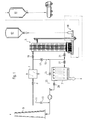
- the overall system shown in Fig. 1 for cleaning Flue gas essentially consists of a precooler 1, which the raw gas to be cleaned in the direction of the arrow via a flap 3 is supplied, as well as from the actual device 5 Cleaning the flue gas, which is a solid separator 7 is connected downstream. The cleaned flue gas is then by means of a fireplace 9 delivered.
- a precooler 1 which the raw gas to be cleaned in the direction of the arrow via a flap 3 is supplied, as well as from the actual device 5
- Cleaning the flue gas which is a solid separator 7 is connected downstream.
- the cleaned flue gas is then by means of a fireplace 9 delivered.
- a parallel connection of several devices 5 the cleaning performance increased or by a series connection of several devices 5 the cleaning of the gases can be improved.
- Fig. 1 The path of the gas through the system in normal operation is shown in Fig. 1 represented by the bold lines and arrows.
- the thin solid lines represent paths that improve operational safety in the event of a fault in one or more components guarantee. So it is with the line 11 and the associated flap 13 around an emergency bypass, with which the entire System bridged and the raw gases fed directly to the chimney 9 can be.
- the device 5 which is shown in Fig. 2a, comprises a Container 31, which the raw gas in the direction of the arrow via a feed opening 33 is supplied.
- the cleaned raw gas is over a discharge opening 35 is discharged in the lower region of the container 31 and the solids separator 7 (FIG. 1), which can be designed, for example, as a fabric filter.
- the container 31 is via an ad / absorbent feed device 37 dry or quasi-dry dusty or powdery adsorbent / absorbent fed.
- the adsorption or absorption of pollutants in the raw gas is improved by the ad / absorbent particles if this one have certain moisture, is in the ad / absorbent feed device 37 water was added while mixing the adsorbent / absorbent, until a predetermined moisture content is reached.
- This can of course automatically in the form of a closed Control loop take place, the moisture content depending on certain parameters, for example the temperature of the supplied Raw gas, can be selected.
- the Moisture content of the adsorbent / absorbent before being fed into the interior of the container 31, for example, up to the limit of the presence a dusty structure can be increased.
- the ad / absorbent However, it is still in dust or powder form before, so that still a high active surface for the Cleaning is available.
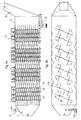
- shafts 39 are provided in the example shown, which run parallel to the longitudinal axis of the container.
- the waves are by means of electric motors 41 attached to the top of the container 31 are arranged, driven in rotation.
- the container 31 can have a wall 31a have, the inner wall of several partially cylindrical regions 31b.
- the four waves are then, as shown in Fig. 2b, preferably arranged so that they are each in the Axis of the partially cylindrical regions 31b lie.
- the shafts 39 can with respect their rotational movement are driven synchronized, so that the chains 43 do not collide in the area of the center of the container.
- This synchronization can be used for cleaning purposes can also be lifted at short notice, so that the chains become worn clean each other.
- the chains can, for example be evenly distributed to avoid unbalance or bending of the shafts a symmetrical one Arrangement of chains in a plane perpendicular to the shaft is preferable is. As shown in Fig. 2b, for example 4 chains can be provided in one level.
- the chains 43 can also create different swirl effects be long.
- the chains can, as shown in Fig. 2a, in the axial direction can also be arranged in groups, with zones of high turbulence alternate with calming zones. Especially in the Transition layers then develop high relative speeds between the ad / absorbent particles and the gas.
- a collecting device 45 for the adsorbent / absorbent which, as in FIG. 3 recognizable more clearly, comprises a conveyor 47 which that accumulates on a conveyor chain 49 (partly with Ad / absorbent loaded with pollutants in a collecting shaft 51 feeds.
- the conveyor chain 49 preferably extends over the entire bottom surface of the container 31.
- Conveying device 53 which by means of another Conveyor chain 55 the ad / absorbent again to the ad / absorbent feeder 37 feeds.
- the latter can do this, for example comprise conveyor section 57 designed as a bucket elevator.
- the Conveyor line 57 is also that by means of the solids separator 7 (Fig. 1) deposited dusty product that largely consists of ad / absorbent supplied. This results in a optimal use of the adsorbent / absorbent.
- the ad / absorbent supply device 37 comprises one Feed device 58 for fresh goods, that is to say fresh adsorbent.
- This fresh material feed device can, as in the figures 1 and 2a, the fresh material at the bottom of the Feed conveyor line 57 from an ad / absorbent silo 62 (FIG. 1).
- the supply of fresh food can also at any point between the ad / absorbent feed opening and the ad / absorbent collection device 45.
- the already amount of circulating ad / absorbent Fresh goods can depend on certain parameters, e.g. the too ad / absorbing amount of pollutant, controlled or regulated become.
- One corresponding to the registered and separated quantity Share of the resulting reaction products is from the ad / absorbent cycle from the collecting shaft 51, as shown in FIG. 3, by means of a discharge device 59, for example can comprise a screw conveyor, discharged and the waste silo 61 (Fig. 1) supplied for disposal.
- a discharge device 59 for example can comprise a screw conveyor, discharged and the waste silo 61 (Fig. 1) supplied for disposal.
- the in circulation the amount of ad / absorbent present becomes essentially constant held.
- the device according to the invention not only results in an improvement in the cleaning efficiency with a simple structure of the device, but also an improvement in the utilization of the adsorbent / absorbent by the reactivation in the adsorbent / absorbent supply device.
- Each ad / absorbent particle passes through the container 31 several times and contributes several times to cleaning the gas.
- the ad / absorbent thus remains - with a corresponding total amount of ad / absorbent within the cycle - for a relatively long time in the cycle (two days and more), which additionally has the advantage that the reaction products formed are caused by the residual oxygen present in the gas and by the Moisture can be oxidized.
- the container 31 is the device 5 formed lying, the shafts 39 perpendicular to the longitudinal axis of the container are arranged in the vertical direction.
- the drive of the shafts remains essentially unchanged.
- the horizontal design of the container 31 results however the advantage that the bearing of the shafts, in particular also on the underside, outside the container interior can and thus protects the bearings from aggressive gases are.
- the feed opening 33 for the raw gas initially widens up to the entire cross section of the container 31, whereby achieved a reduction in flow velocity becomes. In this way, the gases to be cleaned remain inside of the container 31, which leads to an increase in the cleaning effect contributes.
- the chains 43 arranged on the shafts 39 are essentially arranged at equidistant axial distances on the shafts and so distributed over the circumference of the shaft that an unbalance is avoided becomes.
- chains should be provided so that in each perpendicular to the shaft Level an unbalance is excluded.
- the shafts 39 are parallel Inner walls of the container in turn with partially cylindrical Sections 31b 'provided, whereby the already above described advantages result.
- Flow guiding elements can be provided which have an undisturbed gas flow prevent in the direction of the gas discharge openings 35.
- the collecting device 45 for the Ad / absorbent provided in the bottom wall of the container 31 is in the range Gas discharge opening 35 in turn the collecting device 45 for the Ad / absorbent provided.
- the presentation of the Circulation for the adsorbent / absorbent dispensed with is the presentation of the Circulation for the adsorbent / absorbent dispensed with.
- the ad / absorbent particles supplied settle again and again on the bottom wall and are whirled up again.
- the ad / absorbent particles from the gas flow towards the gas discharge opening 35 carried along. Since in the rear area of the container 31, i.e. in the Area of the collecting device 45 no more rotating shafts the ad / absorbent particles are already set largely on the conveyor chain of the collecting device 45. Those particles that are still moving in the direction of the gas flow are taken to the gas discharge opening 35, sit down due to gravity from the diagonally upward Formation of the discharge channel over time on the lower one Wall of the discharge channel and slide due to the relative great steepness of this wall down towards the Collecting device 45.
- the collecting device 45 for the Provide the adsorbent / absorbent with a longer conveyor chain which is driven so that the ad / absorbent located on the conveyor chain conveyed towards the end of the container and from there at the bottom of the conveyor chain towards the collecting shaft is promoted.
- This can be achieved that the Concentration of the ad / absorbent particles in the area of the waves 39, which are located above the conveyor chain, opposite the Ad / absorbent concentration in the front area of the container 31 decreased. In this way, the proportion of ad / absorbent particles discharged through the gas through the gas discharge opening 35.
- the horizontal formation of the shafts 39 wind them Chains 43 at low speed of the shafts, for example when Stop the device to the waves, so that an unobstructed Access to the interior of the container 31 is possible. At at higher speeds, however, the chains are unwound due to the centrifugal force, so that even in this embodiment optimal swirling of the gas / adsorbent mixture is ensured.
- Fig. 6 shows a simplified embodiment of the invention also lying container 31.
- the waves 39 are again horizontal and arranged perpendicular to the longitudinal axis of the container 31.
- this embodiment is only one Row of shafts 39 provided, the chains just as well are long that the chains touch each other is avoided. As a result, synchronization can occur the drives for the shafts 39 are dispensed with.
- This can, as shown in Fig. 6a, either be driven so that the top is the conveyor chain moves in the direction of the gas discharge opening 35, so that the ad / absorbent between the bottom of the conveyor chain and the inner wall of the container towards the collecting shaft the device 45 is promoted.
- the conveyor chain can also be driven in opposite directions so that the ad / absorbent that is on the conveyor chain deposits, again and again in the direction of the gas supply opening 33 is moved.
- the speed of the conveyor chain must then, however be chosen larger than the average movement speed the ad / absorbent particles in the gas stream.
Abstract
Description
Die Erfindung betrifft eine Vorrichtung zur Reinigung von Rauchgas mit den Merkmalen des Oberbegriffs des Patentanspruchs 1.The invention relates to a device for cleaning Flue gas with the features of the preamble of the claim 1.
Zur Rauchgasreinigung, beispielsweise zur Reinigung von Abgasen aus Feuerungsanlagen, finden derzeit im wesentlichen Naß-Verfahren, Halbtrocken-Verfahren und Trocken-Verfahren Anwendung. Dabei weisen Naß-Verfahren und Halbtrocken-Verfahren einen in aller Regel höheren Reinigungswirkungsgrad auf als Trocken-Verfahren. Naß- oder Halbtrocken-Verfahren bedingen jedoch einen höheren Aufwand bei der Zufuhr, Abfuhr und der Wiederaufbereitung des zur Reinigung der Rohgase eingesetzten Ad-/Absorbens. Zudem entstehen in dem Behälter, in welchem das zugegebene Ad-/Absorbens die Absorption oder Adsorption der Schadstoffe bewirkt, extrem aggressive Säuren, die die Behälterinnenwandung bzw. darin befindliche Einrichtungen angreifen. Die mit Salzen aus dem Wäscher abgestoßenen Wässer müssen in einer Abwasseraufbereitungsanlage behandelt werden, was mit einem erheblichen Aufwand verbunden ist, der sich insbesondere bei kleineren Rauchgas-Reinigungsanlagen auswirkt.For flue gas cleaning, for example for cleaning exhaust gases from combustion plants, currently mainly find wet processes, Semi-dry process and dry process application. The wet method and semi-dry method have an in generally higher cleaning efficiency than dry processes. However, wet or semi-dry processes require one higher effort in feeding, removal and reprocessing of the ad / absorbent used to clean the raw gases. In addition, arise in the container in which the added ad / absorbent causes the absorption or adsorption of the pollutants, extremely aggressive acids affecting the inner wall of the container or attack facilities located therein. The one with salts Waters discharged from the scrubber must be in a wastewater treatment plant be dealt with what is significant Effort is associated, particularly in the case of smaller ones Flue gas cleaning systems affects.
Es wurden daher verschiedene Methoden zur Verbesserung des Reinigungswirkungsgrades von trockenen Rauchgasreinigungsverfahren vorgeschlagen. Beispielsweise ist in der EP-A-0 104 335 offenbart, daß die Reaktion zwischen den im Rohgas enthaltenen Schadstoffen und dem Ad-/Absorbens verbessert werden kann, wenn zusätzlich Wasser zugegeben wird. Dies geschieht in der Weise, daß in einer ersten Stufe trockenes, pulverförmiges Reaktionsmittel eingeblasen und in einer zweiten Stufe reines Wasser oder eine wässrige Lösung oder Suspension eines Reaktionsmittels eingedüst wird. Durch das in der zweiten Stufe zugesetzte Wasser kann eine Reaktivierung von Partikeln des Reaktionsmittels erreicht werden. Durch die Zugabe von Wasser kann somit das Reaktionsmittel besser ausgenutzt werden. Various methods for improving the Cleaning efficiency of dry flue gas cleaning processes suggested. For example, EP-A-0 104 335 discloses that the reaction between those contained in the raw gas Pollutants and the ad / absorbent can be improved if additional water is added. This happens in the way that in a first stage dry, powdery reactant blown in and in a second stage pure water or an aqueous solution or suspension of a reactant is injected. Through the water added in the second stage can reactivate particles of the reactant can be achieved. By adding water, this can be done Reagent can be better used.
Nachteilig hierbei ist, daß die zugesetzte Wassermenge so gering gehalten werden muß, daß auch bei relativ niedriger Anfangstemperatur des Abgases der Taupunkt nicht unterschritten wird. Wird dies nicht beachtet, so kann es durch die sich bildenden aggressiven wässrigen Säuren zu einer Beschädigung der Anlage kommen.The disadvantage here is that the amount of water added is so small must be kept that even at a relatively low starting temperature the exhaust gas does not fall below the dew point. Becomes Failure to do so may result from the aggressive being formed aqueous acids can damage the system.
Es ist des weiteren, beispielsweise aus der EP-A-0 029 564, bekannt, daß durch eine intensive Vermischung des Rohgases mit dem zugesetzten trockenen Ad-/Absorbens eine Erhöhung der Relativgeschwindigkeit zwischen dem Gas und den Ad-/Absorbenspartikeln und damit eine Verbesserung der Reaktionsgeschwindigkeit bzw. des Reinigungswirkungsgrades erzielbar ist. Hierzu wird in der EP-A-0 029 564 vorgeschlagen, Schall auf die Reaktionspartner einwirken zu lassen.It is also known, for example from EP-A-0 029 564, that by intensive mixing of the raw gas with the added dry ad / absorbent an increase in the relative speed between the gas and the adsorbent particles and thus an improvement in the reaction rate or the cleaning efficiency can be achieved. For this, in the EP-A-0 029 564 proposed sound on the reactants to take effect.
Aus der DE-A-32 32 080 ist bekannt, daß durch teilweise äußere Rückführung des Ad-/Absorbens bzw. der abgeschiedenen Feststoffe eine Verbesserung der Ausnutzung des Ad-/Absorbens und damit letztendlich eine Ad-/Absorbenseinsparung erreichbar ist.From DE-A-32 32 080 it is known that by partially external Return of the adsorbent / absorbent or the separated solids an improvement in the utilization of the adsorbent and thus ultimately an ad / absorbent savings can be achieved.
Zur Verbesserung des Reinigungswirkungsgrades wird in der EP-B-0 203 430 ein Verfahren bzw. eine Vorrichtung zur Reinigung von Rauchgas vorgeschlagen, wobei das Verhältnis der Verweilzeit eines dem Reaktor zugeführten Ad-/Absorbens zur Verweilzeit des Rauchgases im Reaktor dadurch geregelt und/oder gesteuert wird, daß im Reaktor sich gegenüber dem Reaktorbehälter bewegende Einbauten, beispielsweise in Form einer rotierenden Schnecke, vorgesehen sind. Diese Schnecke kann mit einer Drehzahl von ca. 0,5 bis 120 U/min angetrieben werden, wobei sich das Ad-/Absorbens teilweise auf den Oberflächen der Schnecke ablagert, jedoch immer wieder von den zu reinigenden Rauchgasen bzw. von zusätzlich eingeblasener Druckluft aufgewirbelt wird. Somit kann insbesondere die Verweilzeit der schwereren Ad-/Absorbenspartikel relativ zur Verweilzeit des Gases im Reaktor gesteuert bzw. geregelt werden. To improve the cleaning efficiency, EP-B-0 203 430 a method and a device for cleaning Flue gas is proposed, the ratio of the residence time an ad / absorbent fed to the reactor at the residence time of the Flue gas is regulated and / or controlled in the reactor, that moving in the reactor relative to the reactor vessel Internals, for example in the form of a rotating screw, are provided. This worm can run at a speed of approx. 0.5 to 120 U / min are driven, the ad / absorbent partially deposited on the surfaces of the snail, however again and again of the flue gases to be cleaned or of additional blown compressed air is whirled up. Thus, in particular the dwell time of the heavier ad / absorbent particles controlled relative to the residence time of the gas in the reactor or be managed.
Nachteilig bei dieser Vorrichtung bzw. diesem Verfahren ist jedoch, daß sich mit zunehmender Betriebszeit des Reaktors sowohl an der Behälterinnenwandung als auch auf der Oberfläche der sich bewegenden Einbauten eine harte Schicht ablagert, welche durch die im Reaktor befindlichen Feststoffe gebildet wird. Diese extrem harte und zähe Schicht kann praktisch nur mit bergmännischen Mitteln abgebaut werden.A disadvantage of this device or this method is however, that with increasing reactor uptime both on the inside of the container as well as on the surface of the moving internals a hard layer, which is formed by the solids in the reactor. This extremely hard and tough layer can practically only with mining Funds are reduced.
Betriebserfahrungen mit vorgenannten Vorrichtungen bzw. Verfahren haben gezeigt, daß ein gleichmäßiges Zerstäubungsbild des eingesprühten Wassers und eine gleichmäßige Verteilung der Feststoffe im Verhältnis zur Rauchgasmenge nicht erzielbar ist. Aufgrund der sich daraus ergebenden ungleichmäßigen und ineffektiven Vermischung von Rauchgas und Ad-/Absorbens ist es unumgänglich, daß nasse Zonen zu Anbackungen führen und trockene Zonen unbefriedigend absorbieren.Operating experience with the aforementioned devices or processes have shown that a uniform atomization of the sprayed water and an even distribution of solids is not achievable in relation to the amount of flue gas. Because of the resulting uneven and ineffective Mixing flue gas and adsorbent / absorbent is essential that wet zones lead to caking and dry ones Absorb zones unsatisfactorily.
Schließlich ist aus der EP-A-0 342 559 eine Vorrichtung zum Abscheiden von Stäuben und/oder sauren Schadstoffen aus Gasen sowie ein Gliederkopf für eine derartige Vorrichtung bekannt, wobei im unteren und oberen Bereich des Reaktorgefässes ein um eine vertikale Achse rotierend antreibbarer Gliederkopf angeordnet ist. Am Gliederkopf bzw. an dessen Nabe sind mehrere kettenförmige Glieder angeordnet, die sich bei einer Rotation des Gliederkopfes bis fast an die Wandung erstrecken. Hierdurch kann eine Krustenbildung an der Wandung im Bereich der Glieder vermieden werden. Im Reaktorgefäß wird der Gasstrom mittels entsprechender Leitwandungen mehrfach umgelenkt.Finally, EP-A-0 342 559 describes a device for Separation of dust and / or acidic pollutants from gases and a link head for such a device are known, a in the lower and upper area of the reactor vessel a vertical axis rotatably driven link head arranged is. There are several chain-shaped on the link head or on its hub Arranged arranged when the rotation of the Extend the link head almost to the wall. This can avoid crusting on the wall in the area of the limbs become. In the reactor vessel, the gas flow is controlled by means of a corresponding Guide walls deflected several times.
Ausgehend von diesem Stand der Technik liegt der vorliegenden Erfindung die Aufgabe zugrunde, eine Vorrichtung zur Reinigung von Rauchgas, insbesondere zur trockenen Reinigung von Rauchgas, zu schaffen, welche einen hohen Reinigungswirkungsgrad aufweist, bei der wesentliche Beeinträchtigungen der Funktion durch Ablagerungen an der Behälterinnenwandung oder auf sich bewegenden Teilen vermieden werden und welche gleichzeitig eine flexible Bauweise ermöglicht.Based on this prior art, the present Invention, the object of an apparatus for cleaning of flue gas, especially for dry cleaning of flue gas, to create, which has a high cleaning efficiency, at the substantial impairment of function due to deposits on the inside of the container or on moving Parts are avoided and which are flexible at the same time Construction allows.
Die Erfindung löst diese Aufgabe mit den Merkmalen des Patentanspruchs 1.The invention solves this problem with the features of the claim 1.
Die Erfindung beruht auf der Erkenntnis, daß durch das Vorsehen flexibler Verwirbelungselemente, welche von den bewegbaren Einbauten umfaßt sind, die Bildung von störenden Schichten von vornherein vermieden bzw. stark reduziert wird und dann durch eine Formänderung der flexiblen Verwirbelungselemente auf einfache Weise beseitigt werden können.The invention is based on the knowledge that by providing flexible swirling elements, which of the movable internals are included, the formation of interfering layers of is avoided in advance or greatly reduced and then by a change in shape of the flexible swirling elements to simple Way can be eliminated.
Des Weiteren kann eine gegebenenfalls an der Innenwandung des Behälters entstehende Schicht die Funktion der Vorrichtung nie so weit beeinträchtigen, daß eine Bewegung der bewegbaren Einbauten in wesentlichem Maß beeinträchtigt wird, wie dies beispielsweise bei der Vorrichtung gemäß der EP-B-0 203 430 der Fall ist, wenn die rotierende Schnecke mit einer sich an die Behälterinnenwandung entstehenden Schicht in Berührung kommt.Furthermore, one can optionally on the inner wall of the The resulting layer never functions as a device impair so far that movement of the movable internals is significantly impaired, such as this in the device according to EP-B-0 203 430 Case is when the rotating snail with a turn to the The inner layer of the container comes into contact.
Das Entstehen von Ablagerungsschichten auf den flexiblen Verwirbelungselementen kann beispielsweise dadurch verhindert werden, daß in bestimmten zeitlichen Abständen eine Änderung der Bewegungsgeschwindigkeit der Verwirbelungselemente vorgenommen wird, so daß sich die Form der flexiblen Elemente verändert und hierdurch gegebenenfalls bereits entstandene dünne Ablagerungsschichten abgesprengt werden.The formation of deposits on the flexible interlacing elements can be prevented, for example, that at certain intervals a change in the Movement speed of the swirling elements made is, so that the shape of the flexible elements changes and this may result in thin deposits be blown off.
Infolge der einen oder mehreren senkrecht zur Längsachse des Behälters angeordneten Wellen (ob bei vertikaler oder horizontaler Anordnung des Behälters) ergibt sich der Vorteil, daß ein modularer Aufbau des Behälters möglich ist. Je nach gewünschter Reinungsleistung bzw. gewünschter Reinheit des gereinigten Gases kann somit eine erforderliche Anzahl von Modulen zu einem Behälter kombiniert werden. Dies reduziert die Kosten bei der Planung und beim Bau einer Rauchgasreinigungsanlage erheblich. Des weiteren sind nachträgliche Änderungen einer bestehenden Anlage auf einfache und kostengünstige Weise möglich.As a result of the one or more perpendicular to the longitudinal axis of the Container arranged shafts (whether vertical or horizontal Arrangement of the container) there is the advantage that a modular construction of the container is possible. Depending on the desired Cleaning performance or desired purity of the cleaned gas can thus add a required number of modules to a container be combined. This reduces planning costs and significantly when building a flue gas cleaning system. Of further are subsequent changes to an existing system possible in a simple and inexpensive way.
Bei der bevorzugten Ausführungsform der Erfindung sind die flexiblen Verwirbelungselemente als Ketten oder Seile ausgebildet, die an einer oder mehreren rotierbar angetriebenen Wellen angeordnet sind. Hierdurch ergibt sich der Vorteil eines mechanisch einfachen und kostengünstigen Aufbaus, wobei insbesondere die Ausbildung der Verwirbelungselemente als Ketten dazu führt, daß bei einer Änderung der Rotationsrichtung oder der Rotationsgeschwindigkeit eine Veränderung der Lage der Kettenglieder gegeneinander und gegen die Welle erfolgt, so daß bereits entstandene Ablagerungsschichten abgesprengt bzw. abgerieben werden.In the preferred embodiment of the invention, the are flexible Interlacing elements designed as chains or ropes, arranged on one or more rotatably driven shafts are. This gives the advantage of a mechanical simple and inexpensive construction, in particular the Training the swirling elements as chains leads to the fact that when the direction of rotation or the speed of rotation change a change in the position of the chain links against each other and against the wave, so that already created Deposition layers are blasted off or rubbed off.
Zudem ergibt sich der Vorteil, daß an der Innenwandung des Behälters entstehende Ablagerungsschichten von den Kettengliedern immer wieder abgeschlagen werden, sobald diese Schichten so dick werden, daß sie mit den Kettenenden in Berührung gelangen.In addition, there is the advantage that on the inner wall of the container resulting layers of deposits from the chain links be knocked off again and again as soon as these layers are so thick that they come into contact with the chain ends.
Die Erfindung bietet somit den Vorteil einer selbsttätigen Reinigung sowohl der flexiblen Verwirbelungselemente als auch der Behälterinnenwandung.The invention thus offers the advantage of an automatic Cleaning both the flexible swirling elements as well the inner wall of the container.
Die Rotation der flexiblen Verwirbelungselemente erfolgt mit einer solchen Geschwindigkeit, daß durch die hieraus resultierende Verwirbelung des Rohgas-Ad-/Absorbens-Gemisches die Reaktionsgeschwindigkeit und damit der Reinigungswirkungsgrad aufgrund der sich ergebenden hohen Relativgeschwindigkeiten zwischen den Ad-/Absorbenspartikel und dem Rohgas verbessert wird. Im Gegensatz zu den starren bewegten Einbauten gemäß der EP-B-0 203 430 dienen die flexiblen Verwirbelungselemente der erfindungsgemäßen Vorrichtung in erster Linie dazu, eine ausreichende Verwirbelung des Rohgas-Ad-/Absorbens-Gemisches zu erreichen. Selbstverständlich kann durch die entsprechende Wahl der Rotationsgeschwindigkeit der flexiblen Verwirbelungselemente und der hierdurch verursachten Verlängerung des Wegs der Ad-/Absorbenspartikel im zu reinigenden Rohgas auch in gewissen Grenzen das Verhältnis der Verweilzeit des Ad-/Absorbens zur Verweilzeit des Gases im Reaktor gesteuert werden.The flexible swirling elements are rotated with such a speed that the resulting Whirling the raw gas / adsorbent mixture the reaction rate and thus the cleaning efficiency due to the resulting high relative speeds between the ad / absorbent particles and the raw gas is improved. In contrast to the rigid moving components according to EP-B-0 203 430 serve the flexible swirling elements of the invention Device primarily to be sufficient To achieve turbulence in the raw gas / adsorbent mixture. Of course, by choosing the appropriate rotation speed the flexible swirling elements and the this causes an extension of the path of the ad / absorbent particles in the raw gas to be cleaned, even within certain limits Ratio of the residence time of the adsorbent to the residence time of the Gases can be controlled in the reactor.
Des Weiteren ergibt sich der Vorteil einer geringen Druckdifferenz zwischen Gaszuführ- und Gasabführseite des Behälters, da keinerlei feste Einbauten erforderlich sind, die einen Druckabfall mit sich bringen.Furthermore, there is the advantage of a low pressure difference between the gas supply and gas discharge side of the container, because no fixed fixtures are required that cause a pressure drop entail.
Des Weiteren ist durch die Verwendung von flexiblen Verwirbelungselementen eine hohe Beladung des Rauchgases mit Ad-/Absorbens möglich, da durch eine hohe Rotations- bzw. Bewegungsgeschwindigkeit der Verwirbelungselemente ein hoher Verwirbelungsgrad erreicht wird und eine Bildung von Ablagerungsschichten innerhalb des Behälters nicht zu befürchten ist. Wegen des hohen Durchsatzes von staubförmigem Feststoff kann eine hohe Beladung mit rückgeführtem, d.h. nur noch teilweise adsorptionsfähigem bzw. absorbtionsfähigem Ad-/Absorbens erfolgen, wobei das stöchiometrische Verhältnis des noch aktiven Teil des Ad-/Absorbens zur Menge der zu adsorbierenden bzw. absorbierenden Stoffe wegen der hohen Verwirbelung nahe an Eins liegen kann, vorzugsweise im Bereich zwischen 1,0 und 1,5. Hierdurch ergibt sich der Vorteil einer optimalen Ausnutzung des Ad-/Absorbens, da dieses relativ lange Zeit innerhalb eines Kreislaufs gehalten werden kann.Furthermore, by using flexible swirling elements a high loading of the flue gas with adsorbent / absorbent possible because of a high rotation or movement speed the swirling elements have a high degree of swirling is achieved and the formation of deposits there is no fear inside the container. Because of the high Throughput of dusty solid can be a high load with returned, i.e. only partially adsorptive or absorbent ad / absorbent, the stoichiometric ratio of the still active part of the adsorbent / absorbent the amount of adsorbing or absorbing Substances can be close to one because of the high turbulence, preferably in the range between 1.0 and 1.5. This gives the advantage of optimal use of the adsorbent / absorbent, since this is kept within a cycle for a relatively long time can be.
Durch die hohen Rotations- bzw. Bewegungsgeschwindigkeiten der flexiblen Verwirbelungselemente kommt es zusätzlich zu dem durch das Aufeinandertreffen von Ad-/Absorbenspartikel untereinander bewirkten Abrieb zu einem Zerschlagen von größeren Ad-/Absorbenspartikel. Zusätzlich zur Befreiung von Ad-/Absorbenspartikeln von hinsichtlich der gewünschten Adsorption bzw. Absorption inaktiven Oberflächenschichten ist somit die Erzeugung neuer aktiver Oberflächen möglich. Due to the high rotation and movement speeds of the flexible swirling elements also come through the encounter of ad / absorbent particles with one another caused abrasion to smash larger ad / absorbent particles. In addition to the removal of ad / absorbent particles of the desired adsorption or absorption inactive surface layers are thus the creation of new ones active surfaces possible.
Schließlich ergibt sich bei der erfindungsgemäßen Vorrichtung der Vorteil einer einfachen Demontierbarkeit der bewegbaren Einbauten, da beispielsweise die Wellen mittels Flansche geringen Durchmessers am Behälter befestigt werden können, so daß nach der Demontage eines Flansches die Welle samt der flexiblen Verwirbelungselemente entnommen werden kann. Aufgrund der Flexibilität der Verwirbelungselemente ist hierfür nur eine Öffnung relativ geringen Ausmaßes und damit ein Flansch geringen Durchmessers erforderlich.Finally, the device according to the invention results the advantage of easy removal of the movable Built-in components, since the shafts, for example, are small thanks to flanges Diameter can be attached to the container so that after dismantling a flange, the shaft including the flexible Swirling elements can be removed. Because of the flexibility the swirling elements is only an opening for this relatively small size and thus a flange of small diameter required.
Schließlich ergibt sich aufgrund des Fehlens starrer bewegter Einbauten der Vorteil einer guten Begehbarkeit bzw. Zugänglichkeit des Behälters im Stillstand, da die flexiblen Einbauten unter dem Einwirken der Schwerkraft nach unten hängen und weitgehend Raum für eine gute Begehbarkeit bzw. Zugänglichkeit lassen. Reparaturen innerhalb des Behälters oder ein Austausch der flexiblen Elemente sind somit auf einfache Weise möglich.Finally, due to the lack of more rigid movements Built-in the advantage of good accessibility or accessibility of the container at a standstill because of the flexible internals hanging down under the action of gravity and largely Space for good accessibility and accessibility to let. Repairs inside the container or an exchange the flexible elements are thus possible in a simple manner.
Da im Stillstand der Anlage die flexiblen Verwirbelungselemente die Durchgängigkeit der Vorrichtung für das Rohgas nicht blokkieren können, ergibt sich des weiteren eine Betriebssicherheit auch bei Stillstand der Verwirbelungselemente, wenn auch bei geringerem Wirkungsgrad.Because the flexible swirling elements are at a standstill do not block the continuity of the device for the raw gas operational safety even when the swirling elements are at a standstill, even if lower efficiency.
Die Ausbildung der flexiblen Verwirbelungselemente als Ketten oder Seile führt zu dem Vorteil preisgünstiger Ersatz-Verschleißteile.The formation of the flexible swirling elements as chains or ropes leads to the advantage of inexpensive replacement wear parts.
In einer Ausführungsform der Erfindung sind die flexiblen Verwirbelungselemente entlang einer Schraubenlinie am Umfang einer oder mehrerer Wellen angeordnet. Hierdurch ergibt sich der Vorteil einer in gewissem Umfang erzeugbaren Strömungskomponente in Förderrichtung der bei Rotation der Welle entstehenden Schnecke. Selbstverständlich können an einer Welle auch mehrere Abschnitte solche Schrauben vorgesehen sein, deren Förderrichtung auch gegenläufig sein kann. In one embodiment of the invention, the flexible swirling elements are along a helix on the circumference of a or several waves arranged. This gives the advantage a flow component that can be generated to a certain extent in Direction of conveyance of the worm resulting from the rotation of the shaft. Of course, several sections can be on a shaft such screws may be provided, the direction of conveyance also can be opposite.
Bei der bevorzugten Ausführungsform der Erfindung sind die flexiblen Verwirbelungselemente an einer oder mehreren Wellen jeweils in axialer Richtung der Wellen aufgeteilt in mehreren Gruppen vorgesehen, wobei vorzugsweise die Gruppen jeder Welle in jeweils gleichen axialen Abschnitten zwischen zwei senkrecht zu den Wellen liegenden Ebenen vorgesehen sind.In the preferred embodiment of the invention, the flexible swirling elements on one or more shafts each divided into several in the axial direction of the shafts Groups are provided, preferably the groups of each wave in the same axial sections between two perpendicular to the waves lying planes are provided.
Der Behälter kann bei der Vorrichtung nach der Erfindung sowohl liegend als auch stehend eingesetzt werden, wodurch die Vorrichtung einem vorhandenen Platzbedarf sehr flexibel angepaßt werden kann.The container can both in the device according to the invention be used lying as well as standing, which makes the device can be adapted very flexibly to an existing space requirement can.
Der Behälter kann einen im wesentlichen rechteckigen Querschnitt aufweisen, wobei die parallel zu den Wellen liegenden Wandungen des Behälters Innenseiten aufweisen, die aus mehreren teilzylindrischen Bereichen bestehen. Jede Welle ist dabei vorzugsweise im wesentlichen in der Achse eines Teilzylinders vorgesehen. Hierdurch ergibt sich eine verbesserte Verwirbelung des Gas-Ad-/Absorbens-Gemisches. Durch die Ausbildung der Innenwandung in Form mehrerer teilzylindrischer Bereiche wird gegenüber einem rein zylindrischen Aufbau die Gefahr einer quasi-laminaren Strömung des Gemisches vermieden.The container can have a substantially rectangular cross section have, the walls lying parallel to the waves of the container have inner sides, which consist of several partially cylindrical Areas exist. Each wave is preferred provided essentially in the axis of a partial cylinder. This results in an improved swirling of the gas / adsorbent mixture. By forming the inner wall in The shape of several part-cylindrical areas is compared to one purely cylindrical structure the danger of a quasi-laminar flow of the mixture avoided.
Um zu vermeiden, daß an den Innenseiten der zu den Wellen senkrechten Wandungen des Behälters keine oder nur eine geringe Verwirbelung des Gemisches erfolgt, können an diesen Innenseiten Strömungsleitelemente vorgesehen sein oder Bereiche der Innenseiten entsprechend ausgeformt sein. In einer einfachen Ausführungsform können diese Strömungsleitelemente wiederum als kreiszylindrische Wandungen ausgebildet sein, die koaxial zu den Wellen angeordnet sind. To avoid that on the inside of the perpendicular to the waves Walls of the container no or only a little Whirling of the mixture takes place on these inner sides Flow guiding elements can be provided or areas of the inner sides be shaped accordingly. In a simple embodiment can these flow guide elements in turn as circular cylindrical Walls are formed which are coaxial to the Waves are arranged.
In der bevorzugten Ausführungsform der Erfindung ist für das Rohgas und das Ad-/Absorbens wenigstens je eine Zuführöffnung vorgesehen. Selbstverständlich kann jedoch auch das Mischen des Ad-/Absorbens mit dem Rohgas auch an einer dem Behälter vorgelagerten Stelle erfolgen.In the preferred embodiment of the invention is for Raw gas and the adsorbent / absorbent each have at least one feed opening intended. Of course, mixing the Ad / absorbent with the raw gas also in front of the container Place.
In der Ausführungsform der Erfindung mit stehendem Behälter kann die Reinigung des Gases selbstverständlich im Gleichstrom- oder Gegenstromprinzip erfolgen, wobei die Strömungsrichtung des Gases jeweils entweder von unten nach oben oder umgekehrt verlaufen kann. Die Zuführöffnungen für das Ad-/Absorbens und die Zufuhr bzw. Abfuhr des Gases sind hierzu in entsprechender Weise vorzusehen.In the embodiment of the invention with a standing container can the cleaning of the gas of course in direct current or Counterflow principle take place, the flow direction of the Gases either run from bottom to top or vice versa can. The feed openings for the adsorbent and the The supply and removal of the gas are in a corresponding manner to provide.
In der Ausführungsform der Erfindung mit liegendem Behälter kommt im wesentlichen nur die Reinigung im Gleichstromprinzip in Frage, da durch den Gasstrom eine Beförderung der Ad-/Absorbenspartikel erfolgt.In the embodiment of the invention with the container lying down essentially only the cleaning in the direct current principle comes in Question, since the gas flow carries the ad / absorbent particles he follows.
In der bevorzugten Ausführungsform der Erfindung ist in einem bodenseitigen Bereich des Behälters eine Sammelvorrichtung für das Ad-/Absorbens vorgesehen, welche vorzugsweise einen Förderer aufweist, der sich über die gesamte Länge des bodenseitigen Bereichs des Behälters oder über einen der Gasabführseite benachbarten bodenseitigen Bereich erstreckt. Bei Bedarf kann der Förderer teilweise mittels eines oder mehrerer Abdeckbleche abgedeckt sein.In the preferred embodiment of the invention is in one bottom area of the container a collecting device for the ad / absorbent provided, which is preferably a conveyor has, which extends over the entire length of the bottom Area of the container or one adjacent to the gas discharge side extends bottom area. If necessary, the Conveyor partly by means of one or more cover plates be covered.
Die Sammelvorrichtung ist dabei vorzugsweise so ausgebildet, daß ein vorbestimmter Teil des Ad-/Absorbens dem Behälter in Form eines Kreislaufs wieder zuführbar ist, wobei das im Sammelschacht befindliche Ad-/Absorbens zur Aufrechterhaltung der Druckdifferenz zwischen der Gaszuführseite und der Gasabführseite des Behälters dient. Hierdurch wird vermieden, daß Gas über den externen Zuführweg des Ad-/Absorbens und die Sammelvorrichtung in unmittelbarer Nähe der Gasabführöffnung in den Behälter gelangt, ohne den korrekten "Reinigungsweg" durchlaufen zu haben. The collecting device is preferably designed such that a predetermined part of the adsorbing / absorbing the container in the form of a cycle can be fed again, this in the collecting shaft located ad / absorbent to maintain the Pressure difference between the gas supply side and the gas discharge side of the container. This will prevent gas via the external feed path of the adsorbent / absorbent and the collecting device in the immediate vicinity of the gas discharge opening in the Container arrives without going through the correct "cleaning route" to have.
Am Behälter der Vorrichtung nach der Erfindung ist die Zuführöffnung einer Ad-/Absorbenszuführvorrichtung vorgesehen. Durch diese Ad-/Absorbenszuführvorrichtung wird die erforderliche Menge Ad-/Absorbens in den Behälter eingebracht und der Teil des Ad-/Absorbens, der von der Sammelvorrichtung endgültig zur Entsorgung abgeführt wird, in Form frischen, unverbrauchten Ad-/Absorbens ersetzt.The feed opening is on the container of the device according to the invention an ad / absorbent supply device is provided. By this ad / absorbent feeder becomes the required one Amount of ad / absorbent introduced into the container and the part of the Ad / absorbent that is finally disposed of by the collection device for disposal is dissipated, in the form of fresh, unused ad / absorbent replaced.
Gleichzeitig kann die Ad-/Absorbenszuführvorrichtung eine Einrichtung zur Beimischung von Wasser bis zu einem vorbestimmten Feuchtegehalt umfassen, wodurch eine Reaktivierung des infolge des letzten Durchlaufs durch den Behälter getrockneten Ad-/Absorbens erreicht wird. Dabei kann es zum einen zu einer Reaktivierung der bereits reagierten Oberflächen der Ad-/Absorbenspartikel kommen und zum anderen wird das Wasser von den Ad-/Absorbenspartikeln infolge Kapillarwirkung auch ins Partikelinnere gesaugt, so daß es aufgrund der plötzlichen Aufheizung nach dem Eintritt in den Behälterinnenraum zu einer plötzlichen Verdampfung des Wassers kommt. Hierdurch werden die Partikel aufgesprengt ("Popcorn-Effekt") und so eine Vergrößerung der adsorbierenden bzw. absorbierenden Oberfläche erreicht.At the same time, the ad / absorbent supply device can be a device for adding water up to a predetermined Moisture content, thereby reactivating the consequent of the last pass through the dried ad / absorbent container is achieved. On the one hand, this can lead to reactivation of the already reacted surfaces of the adsorbent / absorbent particles come and on the other hand the water from the ad / absorbent particles due to capillary action also into the interior of the particle sucked so it is due to the sudden heating after entering the container interior to a sudden Evaporation of the water is coming. This will make the particles blown up ("popcorn effect") and thus an enlargement of the adsorbing or absorbing surface reached.
Durch das Zusetzen von Wasser direkt in das Ad-/Absorbens, bevor dieses in den Behälterinnenraum geleitet wird, ergibt sich zudem der Vorteil, daß eine relativ hohe Feuchtigkeitsmenge in den Behälter einbringbar ist, ohne daß nach außen hin eine merkbare Stoffeuchte auftritt. Die makroskopische Struktur des im Kreislauf befindlichen Ad-/Absorbens bleibt unverändert trocken und feinstaubförmig, d.h., das Ad-/Absorbens bleibt auf- bzw. verwirbelbar wie trockener Staub. Gleiches gilt dann selbstverständlich für die entstehenden aggressiven wässrigen Säuren. Auf diese Weise kann somit weitgehend vermieden werden, daß die Innenwandungen des Behälters bzw. die bewegbaren Einbauten durch die entstehenden aggressiven Substanzen angegriffen werden. Zwar ist nicht ausgeschlossen, daß sich an den flexiblen Verwirbelungselementen im Strömungsschatten Schichten des Ad-/Absorbens ansetzen können. Dies wirkt sich durch die Ausbildung der flexiblen Verwirbelungselemente jedoch nicht nachteilig aus.By adding water directly into the ad / absorbent before this is passed into the interior of the container also results the advantage that a relatively high amount of moisture in the Container can be introduced without a noticeable outward Fabric moisture occurs. The macroscopic structure of the circulatory system located ad / absorbent remains dry and fine dust, i.e. the adsorbent can be swirled up or swirled like dry dust. The same applies of course for the resulting aggressive aqueous acids. On this way it can largely be avoided that the Inner walls of the container or the movable internals through the resulting aggressive substances are attacked. Though it is not excluded that the flexible swirling elements in the flow shadow layers of the adsorbent / absorbent can start. This affects the training of flexible Swirling elements, however, are not disadvantageous.
Diese Verfahrensweise des Beimischens von Wasser in das Ad-/Absorbens vor dessen Zuführen in den Behälter und die hierfür notwendigen Vorrichtungen können selbstverständlich auch in Kombination mit bekannten trockenen Rauchgasreinigungsverfahren und -vorrichtungen verwendet werden. Selbstverständlich kann in Verbindung mit den bekannten Behältern nicht der Vorteil eines hohen Reinigungswirkungsgrades durch den mit dem erfindungsgemäßen Behälter möglichen hohen und effektiven Durchsatz von Ad-/Absorbens erreicht werden.This procedure of adding water to the adsorbent / absorbent before it is fed into the container and for this necessary devices can of course also in Combination with known dry flue gas cleaning processes and devices are used. Of course, in Connection with the known containers is not an advantage high cleaning efficiency by the with the invention Containers possible high and effective throughput of adsorbent / absorbent can be achieved.
Wird als Ad-/Absorbens Kalkhydrat (Ca(OH)2) verwendet, so kann anstelle einer Einrichtung zur Beimischung von Wasser eine Einrichtung zur Beimischung von Kalkmilch vorgesehen sein. Mit anderen Worten, die erforderliche Zugabe von frischem Ad-/Absorbens in Form von trockenem Kalkhydrat und die separate Zugabe von Wasser kann dadurch ersetzt werden, daß in einem einzigen Zugabevorgang Kalkmilch beigegeben wird. Hierdurch reduziert sich zum einen der Aufwand für die Ad-/Absorbenszuführvorrichtung und zum anderen ergibt sich der Vorteil, daß die zuzugebende Kalkmilch aus Branntkalk (CaO) und Wasser hergestellt werden kann. An die Filteranlage muß somit lediglich Branntkalk angeliefert werden (es wird hier davon ausgegangen, daß Wasser ohnehin vor Ort vorhanden ist), wobei die benötigte Menge Branntkalk weitaus geringer ist, als die vergleichbar benötigte Menge Kalkhydrat. Hierdurch ergibt sich eine Reduzierung von Transportkosten.If hydrated lime (Ca (OH) 2 ) is used as the adsorbent / absorbent, instead of a device for adding water, a device for adding lime milk can be provided. In other words, the required addition of fresh ad / absorbent in the form of dry hydrated lime and the separate addition of water can be replaced by adding lime milk in a single addition. On the one hand, this reduces the effort for the ad / absorbent feed device and, on the other hand, there is the advantage that the lime milk to be added can be produced from quicklime (CaO) and water. So only quicklime has to be delivered to the filter system (it is assumed here that water is available on site anyway), the amount of quicklime required being far less than the comparable amount of hydrated lime. This results in a reduction in transportation costs.
Zum Anfahren der Vorrichtung ist in diesem Fall erforderlich, daß der Sammelschacht der Sammelvorrichtung vor einer Inbetriebnahme mit staubförmigem Ad-/Absorbens gefüllt wird.In this case, to start the device, that the collecting shaft of the collecting device before commissioning is filled with dust-like adsorbent / absorbent.
Durch die spezielle Ausbildung der bewegten Einbauten als flexible Einbauten, die einen hohen Durchsatz von Ad-/Absorbens ermöglicht, kann bei der Vorrichtung nach der Erfindung als Ad-/Absorbens auch Calciumsilicathydrat (CaSiOH) bis zu einer Korngröße von 5 mm und mehr verwendet werden. Calciumsilicathydrat fällt in dieser Form als Abfall bei der Gasbetonherstellung an und stellt somit ein sehr kostengünstiges Ad-/Absorbens dar. Wegen der hierbei anfallenden relativ großen Partikel war die Verwendung mit bekannten Vorrichtungen jedoch nicht möglich bzw. wegen der erforderlichen Aufbereitung des Calciumsilicathydrats unrentabel.Due to the special design of the moving components as flexible Internals that have a high throughput of adsorbent / absorbent enables, can in the device according to the invention as an adsorbent also calcium silicate hydrate (CaSiOH) up to a grain size of 5 mm and more can be used. Calcium silicate hydrate accumulates in this form as waste in the manufacture of gas concrete and thus represents a very inexpensive ad / absorbent. Because of the relatively large particles produced here, the However, use with known devices is not possible or because of the necessary treatment of the calcium silicate hydrate unprofitable.
Weitere Ausführungsformen der Erfindung ergeben sich aus den Unteransprüchen.Further embodiments of the invention result from the Subclaims.
Die Erfindung wird nachfolgend anhand in der Zeichnung dargestellter Ausführungsbeispiele näher erläutert. In der Zeichnung zeigen:
- Fig. 1
- eine schematische Darstellung einer gesamten Anlage zur Reinigung von Rauchgas;
- Fig. 2
- eine Darstellung einer ersten Ausführungsform der Vorrichtung nach der Erfindung im Schnitt (Fig. 2a Längsschnitt; Fig. 2b Querschnitt durch den Behälter);
- Fig. 3
- einen Teilschnitt durch die Ad-/Absorbens-Sammelvorrichtung gemäß der Linie I-I in Fig. 2a;
- Fig. 4
- eine weitere Ausführungsform der Erfindung mit liegendem Behälter in zwei Längsschnittdarstellungen in zwei zueinander senkrechten Ebenen;
- Fig. 5
- eine weitere Ausführungsform der Erfindung mit liegendem Behälter in der Darstellungsform gemäß Fig. 4 und
- Fig. 6
- eine weitere vereinfachte Ausführungsform der Erfindung mit liegendem Behälter in einer Darstellungsform gemäß den Figuren 4 und 5.
- Fig. 1
- a schematic representation of an entire plant for cleaning flue gas;
- Fig. 2
- a representation of a first embodiment of the device according to the invention in section (Fig. 2a longitudinal section; Fig. 2b cross section through the container);
- Fig. 3
- a partial section through the ad / absorbent collecting device along the line II in Fig. 2a;
- Fig. 4
- a further embodiment of the invention with a lying container in two longitudinal sectional views in two mutually perpendicular planes;
- Fig. 5
- a further embodiment of the invention with a horizontal container in the form of representation according to FIGS. 4 and
- Fig. 6
- a further simplified embodiment of the invention with a lying container in a representation according to Figures 4 and 5.
Die in Fig. 1 dargestellte Gesamtanlage zur Reinigung von
Rauchgas besteht im wesentlichen aus einem Vorkühler 1, welchem
das zu reinigende Rohgas in Pfeilrichtung über ein Klappe 3
zugeführt wird, sowie aus der eigentlichen Vorrichtung 5 zur
Reinigung des Rauchgases, welcher ein Feststoffabscheider 7
nachgeschaltet ist. Das gereinigte Rauchgas wird dann mittels
eines Kamins 9 abgegeben. Selbstverständlich kann auch durch
eine Parallelschaltung mehrerer Vorrichtungen 5 die Reinigungsleistung
erhöht bzw. durch eine Reihenschaltung mehrerer Vorrichtungen
5 die Reinigung der Gase verbessert werden.The overall system shown in Fig. 1 for cleaning
Flue gas essentially consists of a precooler 1, which
the raw gas to be cleaned in the direction of the arrow via a flap 3
is supplied, as well as from the actual device 5
Cleaning the flue gas, which is a
Der Weg des Gases durch die Anlage im Normalbetrieb ist in Fig. 1 durch die fett ausgezogenen Linien und Pfeile dargestellt.The path of the gas through the system in normal operation is shown in Fig. 1 represented by the bold lines and arrows.
Die dünn ausgezogenen Linien stellen Wege dar, die die Betriebssicherheit
im Störfall einer oder mehrerer Komponenten
gewährleisten. So handelt es sich bei der Leitung 11 und dem
zugehörigen Klappe 13 um einen Not-Bypass, mit welchem die gesamte
Anlage überbrückt und die Rohgase direkt dem Kamin 9 zugeführt
werden können.The thin solid lines represent paths that improve operational safety
in the event of a fault in one or more components
guarantee. So it is with the
Mittels der Leitung 15 und dem zugehörigen Klappe 17 kann in
Verbindung mit einer entsprechenden Ansteuerung der Klappen 19
und 21 eine Überbrückung der Vorrichtung 5 vorgenommen werden.By means of the
Schließlich kann mittels der Leitung 23 und einer entsprechenden
Ansteuerung der Klappen 25, 27 und 29 eine Überbrückung des
Feststoffabscheiders 7 erfolgen.Finally, by means of
Die Vorrichtung 5, die in Fig. 2a dargestellt ist, umfaßt einen
Behälter 31, welchem das Rohgas in Pfeilrichtung über eine Zuführöffnung
33 zugeführt wird. Das gereinigte Rohgas wird über
eine Abführöffnung 35 im unteren Bereich des Behälters 31 abgeführt
und dem Feststoffabscheider 7 (Fig. 1) zugeführt, der
beispielsweise als Gewebefilter ausgebildet sein kann. Dem Behälter
31 wird über eine Ad-/Absorbenszuführvorrichtung 37
trockenes bzw. quasi-trockenes staub- bzw. pulverförmiges Ad-/Absorbens
zugeführt.The device 5, which is shown in Fig. 2a, comprises a
Da die Adsorption bzw. Absorption von Schadstoffen im Rohgas
durch die Ad-/Absorbenspartikel verbessert wird, wenn diese eine
gewisse Feuchte aufweisen, wird in der Ad-/Absorbenszuführvorrichtung
37 unter Mischen des Ad-/Absorbens Wasser zugegeben,
bis ein vorbestimmter Feuchtegehalt erreicht ist. Dies kann
selbstverständlich selbsttätig in Form eines geschlossenen
Regelkreises erfolgen, wobei der Feuchtegehalt abhängig von
bestimmten Parametern, beispielsweise der Temperatur des zugeführten
Rohgases, gewählt werden kann. Auf diese Weise kann der
Feuchtegehalt des Ad-/Absorbens vor dem Zuführen in das Innere
des Behälters 31 beispielsweise bis zur Grenze des Vorliegens
einer staubförmigen Struktur erhöht werden. Das Ad-/Absorbens
liegt dabei jedoch noch immer in staub- bzw. pulverförmiger Form
vor, so daß nach wie vor eine hohe aktive Oberfläche für die
Reinigung verfügbar ist.Because the adsorption or absorption of pollutants in the raw gas
is improved by the ad / absorbent particles if this one
have certain moisture, is in the ad /
Da zur Steigerung des Wirkungsgrades eine hohe Relativgeschwindigkeit
zwischen den Ad-/Absorbenspartikeln und dem Rohgas wünschenswert
ist, sind in der Längsachse des Behälters 31 mehrere,
im gezeigten Beispiel vier, Wellen 39 vorgesehen, welche
parallel zur Längsachse des Behälters verlaufen. Die Wellen sind
mittels Elektromotoren 41, die an der Oberseite des Behälters 31
angeordnet sind, rotierend angetrieben.Because of a high relative speed to increase the efficiency
between the adsorbent / absorbent particles and the raw gas is desirable
there are several in the longitudinal axis of the
Zur Verwirbelung des Gas-Ad-/Absorbens-Gemisches sind im Behälterinneren
an den Wellen 39 Ketten 43 angeordnet. Diese hängen
unter Einwirkung der Schwerkraft im Stillstand der Wellen nach
unten und erstrecken sich unter Einwirkung der Zentrifugalkraft
bei einer Rotation der Wellen nach außen. Selbstverständlich
können anstelle von Ketten auch beliebige andere flexible Verwirbelungselemente,
beispielsweise Seile, verwendet werden.
Ketten bieten jedoch den Vorteil, daß infolge der Durchbrüche in
den Kettengliedern eine intensivere Verwirbelung erreichbar ist.
An den flexiblen Verwirbelungselementen können in nicht dargestellter
Weise auch kleinere starre oder flexible Elemente zur
Erhöhung des Luftwiderstands vorgesehen sein.For swirling the gas-ad / absorbent mixture are inside the
Wie in Fig. 2 dargestellt, kann der Behälter 31 eine Wandung 31a
aufweisen, deren Innenwandung mehrere teilzylindrische Bereiche
31b aufweist. Die vier Wellen sind dann, wie in Fig. 2b dargestellt,
vorzugsweise so angeordnet, daß diese jeweils in der
Achse der teilzylindrischen Bereiche 31b liegen.As shown in FIG. 2, the
Hierdurch wird zum einen gewährleistet, daß das Gas infolge der
Verwirbelung durch die Verwirbelungselemente 43 jeder Welle von
der Innenwandung der Bereiche 31b wieder in Richtung Behältermitte
geleitet werden. Zur Verbesserung der Verwirbelung können
jeweils benachbarte Wellen 39, wie in Fig. 2b dargestellt, mit
entgegengesetztem Drehsinn angetrieben sein. Die als Ketten
ausgebildeten Verwirbelungselemente 43 sind dann vorzugsweise so
lang gewählt, daß diese bei einer vorbestimmten Drehzahl mit
ihren äußeren Enden einen Außenkreis beschreiben, dessen Durchmesser
nur geringfügig kleiner ist, als der Innendurchmesser der
teilzylindrischen Bereiche 31b. Lagern sich im Verlauf des
Betriebs der Vorrichtung Ad-/Absorbensschichten an der Innenwandung
des Behälters 31 an, so werden diese von den Kettenenden
abgeschlagen, sobald die Schichtdicke einen bestimmten Wert
überschreitet. In jedem Fall ist gegenüber der Verwendung
starrer Verwirbelungselemente erreicht, daß auch bei größeren
Schichtdicken die für die Bewegung der Wellen 39 erforderliche
Antriebsleistung im wesentlichen unverändert bleibt.This ensures on the one hand that the gas due to the
Swirl by the
Um das Anlagern dickerer Schichten an den Verwirbelungselementen
43 zu vermeiden, kann, wie bereits erwähnt, in bestimmten zeitlichen
Abständen die Drehrichtung jeder Welle 39 umgekehrt oder
die Rotationsgeschwindigkeit verändert werden. Hierdurch ergibt
sich eine Formänderung der flexiblen Verwirbelungselemente 43,
wodurch die gegebenenfalls angelagerten Schichten abplatzen.To add thicker layers to the swirling
Wie in Fig. 2b angedeutet, können die Wellen 39 hinsichtlich
ihrer Rotationsbewegung synchronisiert angetrieben werden, so
daß die Ketten 43 im Bereich der Behältermitte nicht aneinanderschlagen.
Zu Reinigungszwecken kann diese Synchronisation
auch kurzfristig aufgehoben werden, so daß die Ketten sich durch
gegenseitiges Aneinanderschlagen reinigen.As indicated in Fig. 2b, the
In axialer Richtung der Wellen 39 können die Ketten beispielsweise
gleichmäßig verteilt angeordnet sein, wobei zur Vermeidung
von Unwuchten bzw. von Verbiegungen der Wellen eine symmetrische
Anordnung von Ketten in einer zur Welle senkrechten Ebene vorzuziehen
ist. Wie in Fig. 2b dargestellt, können beispielsweise
in einer Ebene jeweils 4 Ketten vorgesehen sein. Die Ketten 43
können zur Erzeugung gewünschter Verwirbelungseffekte auch verschieden
lang ausgebildet sein.In the axial direction of the
Die Ketten können, wie in Fig. 2a dargestellt, in axialer Richtung auch in Gruppen angeordnet sein, wobei Zonen hoher Verwirbelung mit Beruhigungszonen abwechseln. Insbesondere in den Übergangsschichten entstehen dann hohe Relativgeschwindigkeiten zwischen den Ad-/Absorbenspartikeln und dem Gas.The chains can, as shown in Fig. 2a, in the axial direction can also be arranged in groups, with zones of high turbulence alternate with calming zones. Especially in the Transition layers then develop high relative speeds between the ad / absorbent particles and the gas.
Am bodenseitigen Ende des Behälters 31 ist eine Sammelvorrichtung
45 für das Ad-/Absorbens vorgesehen, welche, wie aus Fig. 3
deutlicher erkennbar, eine Fördervorrichtung 47 umfaßt, welche
das sich auf einer Förderkette 49 ansammelnde (teilweise mit
Schadstoffen beladene) Ad-/Absorbens einem Sammelschacht 51
zuführt. Die Förderkette 49 erstreckt sich dabei vorzugsweise
über die gesamte bodenseitige Fläche des Behälters 31.At the bottom end of the
Am bodenseitigen Ende des Sammelschachts 51 ist eine weitere
Fördervorrichtung 53 vorgesehen, welche mittels einer weiteren
Förderkette 55 das Ad-/Absorbens erneut der Ad-/Absorbenszuführvorrichtung
37 zuführt. Letztere kann hierzu beispielsweise eine
als Becherwerk ausgebildete Förderstrecke 57 umfassen. Der
Förderstrecke 57 wird auch das mittels des Feststoffabscheiders
7 (Fig. 1) abgeschiedene staubförmige Produkt, das weitgehend
aus Ad-/Absorbens besteht, zugeführt. Hierdurch ergibt sich eine
optimale Ausnützung des Ad-/Absorbens.There is another at the bottom end of the collecting
Des weiteren umfaßt die Ad-/Absorbenszuführvorrichtung 37 eine
Zuführvorrichtung 58 für Frischgut, das heißt frisches Ad-/Absorbens.
Diese Frischgutzuführvorrichtung kann, wie in den Figuren
1 und 2a dargestellt, das Frischgut an der Unterseite der
Förderstrecke 57 aus einem Ad-/Absorbenssilo 62 (Fig. 1) zuführen.
Selbstverständlich kann das Zuführen von Frischgut jedoch
auch an jeder Stelle zwischen der Ad-/Absorbenszuführöffnung und
der Ad-/Absorbenssammelvorrichtung 45 erfolgen. Die dem bereits
im Kreislauf befindlichen Ad-/Absorbens zugeführte Menge an
Frischgut kann abhängig von bestimmten Parametern, z.B. der zu
ad-/absorbierenden Schadstoffmenge, gesteuert oder geregelt
werden.Furthermore, the ad /
Zusätzlich wird mittels der Ad-/Absorbenszuführvorrichtung 37
dem im Kreislauf befindlichen Ad-/Absorbens in bereits oben beschriebener
Weise Wasser bis zu einem bestimmten Feuchtegehalt
zugeführt.In addition, by means of the ad /
Eine der eingetragenen und abgeschiedenen Menge entsprechender
Anteil der entstehenden Reaktionsprodukte wird aus dem Ad-/Absorbenskreislauf
aus dem Sammelschacht 51, wie in Fig. 3 dargestellt,
mittels einer Abführvorrichtung 59, die beispielsweise
eine Förderschnecke umfassen kann, ausgeschleust und dem Reststoffsilo
61 (Fig. 1) zur Entsorgung zugeführt. Die im Kreislauf
befindliche Ad-/Absorbensmenge wird so im wesentlichen konstant
gehalten. One corresponding to the registered and separated quantity
Share of the resulting reaction products is from the ad / absorbent cycle
from the collecting
Durch die im Sammelschacht 51 befindliche Ad-/Absorbensschicht
wird gleichzeitig ein Aufrechterhalten der Druckdifferenz zwischen
der Zuführöffnung 33 und der Abführöffnung 35 für das Gas
erreicht und auf diese Weise verhindert, daß das Rohgas über die
Ad-/Absorbenszuführvorrichtung 37 und den Sammelschacht 51 in
Richtung auf die Abführöffnung 35 gelangt, ohne die korrekte
Reinigungsprozedur durchlaufen zu haben.Through the ad / absorbent layer located in the collecting
Die vorstehende Ausbildung der Ad-/Absorbenszuführvorrichtung 37
und der Ad-/Absorbenssammelvorrichtung 45 gewährleistet den
gewünschten hohen Ad-/Absorbensdurchsatz durch den Behälter 31.
Diese Elemente können selbstverständlich auch mit bekannten
Behältern 31 verwendet werden.The above configuration of the ad /
Insgesamt betrachtet, ergibt sich bei der Vorrichtung nach der
Erfindung nicht nur eine Verbesserung des Reinigungswirkungsgrads
bei gleichzeitig einfachem Aufbau der Vorrichtung, sondern
auch eine Verbesserung der Ausnützung des Ad-/Absorbens durch
die Reaktivierung in der Ad-/Absorbenszuführvorrichtung. Jedes
Ad-/Absorbenspartikel durchläuft mehrfach den Behälter 31 und
trägt mehrfach zu einer Reinigung des Gases bei. Das Ad-/Absorbens
verbleibt somit - bei entsprechender Gesamtmenge von Ad-/Absorbens
innerhalb des Kreislaufs - relativ lange im Kreislauf
(zwei Tage und mehr), wodurch sich zusätzlich der Vorteil ergibt,
daß entstehende Reaktionsprodukte durch den vorhandenen
Restsauerstoff im Gas und durch die Feuchte aufoxidiert werden.
Beispielsweise wird im Ad-/Absorbens vorhandenes Calciumsulfit
(CaSO3) zu Calciumsulfat (CaSO4) aufoxidiert. Dies geschieht
bereits innerhalb des Ad-/Absorbenskreislaufs. Eine nachgeschaltete
Stufe zur Aufoxidation des mittels der Abführvorrichtung 59
abgeführten verbrauchten Ad-/Absorbens ist somit nicht erforderlich.
Nachfolgend wird das in Fig. 4a und Fig. 4b dargestellte weitere
Ausführungsbeispiel der Erfindung beschrieben, wobei lediglich
auf die zu dem Ausführungsbeispiel gemäß den Figuren 2 und 3
bestehenden Unterschiede eingegangen wird. Insbesondere wesentliche
Teile der Sammelvorrichtung 45 für das Ad-/Absorbens und
die Ad-/Absorbenszuführvorrichtung 37 bleiben dem Grunde nach
unverändert.All in all, the device according to the invention not only results in an improvement in the cleaning efficiency with a simple structure of the device, but also an improvement in the utilization of the adsorbent / absorbent by the reactivation in the adsorbent / absorbent supply device. Each ad / absorbent particle passes through the
The further exemplary embodiment of the invention illustrated in FIGS. 4a and 4b is described below, only the differences existing from the exemplary embodiment according to FIGS. 2 and 3 being discussed. In particular, essential parts of the collecting
Wie in Fig. 4a dargestellt, ist der Behälter 31 der Vorrichtung
5 liegend ausgebildet, wobei die Wellen 39 senkrecht zur Längsachse
des Behälters in vertikaler Richtung angeordnet sind. Der
Antrieb der Wellen verbleibt im wesentlichen unverändert.As shown in Figure 4a, the
Durch die liegende Ausbildung des Behälters 31 ergibt sich
jedoch der Vorteil, daß die Lagerung der Wellen, insbesondere
auch an der Unterseite, außerhalb des Behälterinnenraums erfolgen
kann und somit die Lager vor aggressiven Gasen geschützt
sind. Die Zuführöffnung 33 für das Rohgas erweitert sich zunächst
bis auf den gesamten Querschnitt des Behälters 31, wodurch
eine Reduzierung der Strömungsgeschwindigkeit erreicht
wird. Auf diese Weise verbleiben die zu reinigenden Gase innerhalb
des Behälters 31, was zu einer Steigerung der Reinigungswirkung
beiträgt.The horizontal design of the
Die an den Wellen 39 angeordneten Ketten 43 sind im wesentlichen
in äquidistanten axialen Abständen an den Wellen angeordnet und
so über den Umfang der Welle verteilt, daß eine Unwucht vermieden
wird. Selbstverständlich können jedoch auch bei dieser Ausführungsform
wiederum in jeder Ebene mehrere, beispielsweise
vier, Ketten vorgesehen sein, so daß in jeder zur Welle senkrechten
Ebene eine Unwucht ausgeschlossen ist.The
Wie aus Fig. 4b ersichtlich, sind die zu den Wellen 39 parallelen
Innenwandungen des Behälters wiederum mit teilzylinderförmigen
Abschnitten 31b' versehen, wodurch sich die bereits oben
beschriebenen Vorteile ergeben.As can be seen from FIG. 4b, the
Um zu verhindern, daß sich entlang der zu den Wellen senkrecht
verlaufenden Behälterinnenwandungen Beruhigungszonen hinsichtlich
der Verwirbelung ausbilden, können an diesen Innenwandungen
(wie in Verbindung mit Fig. 6 erläutert) nicht dargestellte
Strömungsleitelemente vorgesehen sein, die eine ungestörte Gasströmung
in Richtung auf die Gasabführöffnungen 35 verhindern.To prevent it from being perpendicular to the waves
trending inner walls of calming zones with regard
the vortex can form on these inner walls
(as explained in connection with Fig. 6) not shown
Flow guiding elements can be provided which have an undisturbed gas flow
prevent in the direction of the
In der bodenseitigen Wandung des Behälters 31 ist im Bereich der
Gasabführöffnung 35 wiederum die Sammelvorrichtung 45 für das
Ad-/Absorbens vorgesehen. Diese umfaßt wiederum eine Fördervorrichtung
47, welche sich über die gesamte Breite des Behälters
31 erstreckt. Im übrigen ist die Sammelvorrichtung 45 unverändert,
ebenso wie die Ad-/Absorbenszuführvorrichtung 37. Aus
Gründen der Übersichtlichkeit wurde auf die Darstellung des
Kreislaufs für das Ad-/Absorbens verzichtet.In the bottom wall of the
Bei dieser Ausführungsform der Erfindung ist im wesentlichen nur ein Betrieb nach dem Gleichstromprinzip möglich.In this embodiment of the invention is essentially only Operation according to the direct current principle possible.
Bei der Vorrichtung gemäß Fig. 4 setzen sich die zugeführten Ad-/Absorbenspartikel
immer wieder an der bodenseitigen Wandung ab
und werden erneut aufgewirbelt. Dabei werden die Ad-/Absorbenspartikel
vom Gasstrom in Richtung auf die Gasabführöffnung 35
mitgetragen. Da im hinteren Bereich des Behälters 31, d.h., im
Bereich der Sammelvorrichtung 45 keine rotierenden Wellen mehr
vorgesehen sind, setzen sich die Ad-/Absorbenspartikel bereits
zum großen Teil auf der Förderkette der Sammelvorrichtung 45 ab.
Diejenigen Partikel, die von der Gasströmung noch mit in Richtung
auf die Gasabführöffnung 35 mitgenommen werden, setzen sich
infolge der Schwerkraft durch die schräg aufwärts gerichtete
Ausbildung des Abführkanals im Laufe der Zeit an der unteren
Wandung des Abführkanals ab und rutschen infolge der relativ
großen Steilheit dieser Wandung nach unten in Richtung auf die
Sammelvorrichtung 45. Auf diese Weise ist gewährleistet, daß der
größte Teil des Ad-/Absorbens in die Sammelvorrichtung 45
gelangt. Der bei jeder Ausführungsform vom Gasstrom durch die
Gasabführöffnung abgeführte Anteil des Ad-/Absorbens, insbesondere
kleinere Ad-/Absorbenspartikel, werden dann über den Feststoffabscheider
7 (Fig. 1) zurückgewonnen. In the device according to FIG. 4, the ad / absorbent particles supplied settle
again and again on the bottom wall
and are whirled up again. The ad / absorbent particles
from the gas flow towards the gas discharge opening 35
carried along. Since in the rear area of the
Die Ausführungsform gemäß Fig. 5 unterscheidet sich von der
Ausführungsform nach Fig. 4 lediglich dadurch, daß die Wellen 39
horizontal und senkrecht zur Längsachse des Behälters 31 angeordnet
sind. Somit kann in praktisch vollem Umfang auf die vorstehenden
Ausführungen verwiesen werden.5 differs from that
4 only in that the shafts 39th
arranged horizontally and perpendicular to the longitudinal axis of the
Wie in Fig. 5a dargestellt, ist die Sammelvorrichtung 45 für das
Ad-/Absorbens mit einer längeren Förderkette versehen, welches
so angetrieben ist, daß das auf der Förderkette befindliche Ad-/Absorbens
in Richtung auf das Behälterende gefördert und von da
an der Unterseite der Förderkette in Richtung auf den Sammelschacht
gefördert wird. Hierdurch kann erreicht werden, daß die
Konzentration der Ad-/Absorbenspartikel im Bereich der Wellen
39, die sich oberhalb der Förderkette befinden, gegenüber der
Ad-/Absorbenskonzentration im vorderen Bereich des Behälters 31
verringert. Auf diese Weise reduziert sich auch der Anteil von
durch das Gas über die Gasabführöffnung 35 abgeführten Ad-/Absorbenspartikeln.As shown in Fig. 5a, the collecting
Durch die horizontale Ausbildung der Wellen 39 wickeln sich die
Ketten 43 bei geringer Drehzahl der Wellen, beispielsweise beim
Stillsetzen der Vorrichtung, um die Wellen, so daß ein ungehinderter
Zugang zum Innenbereich des Behälters 31 möglich ist. Bei
höheren Drehzahlen erfolgt jedoch ein Abwickeln der Ketten
infolge der Zentrifugalkraft, so daß auch bei dieser Ausführungsform
eine optimale Verwirbelung des Gas-Ad-/AbsorbensGemisches
sichergestellt ist.The horizontal formation of the
Fig. 6 zeigt eine vereinfachte Ausführungsform der Erfindung bei
ebenfalls liegendem Behälter 31. Ebenso wie bei der Ausführungsform
gemäß Fig. 5 sind die Wellen 39 wiederum horizontal und
senkrecht zur Längsachse des Behälters 31 angeordnet. Im Unterschied
zu dieser Ausführungsform ist jedoch nur eine einzige
Reihe von Wellen 39 vorgesehen, wobei die Ketten auch nur so
lang ausgebildet sind, daß eine Berührung der Ketten untereinander
vermieden ist. Demzufolge kann auf eine Synchronisierung
der Antriebe für die Wellen 39 verzichtet werden.Fig. 6 shows a simplified embodiment of the invention
also lying
Während die obere Wandung des Behälters 31 wiederum die bekannten
teilzylindrischen Bereiche aufweist, erstreckt sich über die
gesamte untere Innenwandung eine Förderkette der Sammelvorrichtung
45 für das Ad-/Absorbens. Dieses kann, wie in Fig. 6a dargestellt,
entweder so angetrieben sein, daß sich die Oberseite
der Förderkette in Richtung auf die Gasabführöffnung 35 bewegt,
so daß das Ad-/Absorbens zwischen der Unterseite der Förderkette
und der Behälterinnenwandung in Richtung auf den Sammelschacht
der Vorrichtung 45 gefördert wird. Hierdurch ergibt sich ein
relativ rascher Durchlauf des Ad-/Absorbens, welches immer
wieder von der Oberseite der Förderkette aufgewirbelt wird.While the upper wall of the
Die Förderkette kann jedoch auch entgegengesetzt angetrieben
werden, so daß das Ad-/Absorbens, das sich auf der Förderkette
ablagert, immer wieder in Richtung auf die Gaszuführöffnung 33
bewegt wird. Die Geschwindigkeit der Förderkette muß dann jedoch
größer gewählt werden, als die mittlere Bewegungsgeschwindigkeit
der Ad-/Absorbenspartikel im Gasstrom. Bei diesem Antrieb der
Förderkette kann die Verweildauer der Ad-/Absorbenspartikel im
Innenraum des Behälters 31 erhöht werden.However, the conveyor chain can also be driven in opposite directions
so that the ad / absorbent that is on the conveyor chain
deposits, again and again in the direction of the
Wie in Fig. 6 dargestellt, können überhalb der Förderkette der
Ad-/Absorbenssammelvorrichtung 45 Strömungsleitelemente 63 vorgesehen
sein, die in Bereichen zwischen den äußeren Kreisbahnen
der Ketten 43 angeordnet sind und eine den kreiszylindrischen
Bereichen 31b' der oberen Wandung entsprechende Funktion ausüben.As shown in Fig. 6, above the conveyor chain
Ad /
Des weiteren sind, wie gestrichelt in Fig. 6a angedeutet und
auch Fig. 6b ersichtlich, an den seitlichen Innenwandungen des
Behälters 31 weitere Strömungsleitelemente 65 vorgesehen, die
verhindern, daß Gas nicht oder nur geringfügig verwirbelt entlang
dieser Wege von der Zuführöffnung 33 zur Abführöffnung 35
gelangt.Furthermore, as indicated by dashed lines in Fig. 6a and
also Fig. 6b can be seen on the side inner walls of the
Claims (19)
- Device for cleaning flue gas, havingcharacterised in thata) a container (31) to which crude gas and an adsorbent/absorbent for cleaning the crude gas can be supplied via at least one supply aperture (33), and from which the cleaned gas can be discharged via at least one discharge aperture (35),b) wherein movable components (39), which have flexible turbulence elements (43), are provided in the container (31),c) the flexible turbulence elements (43) are disposed on at least one rotatably driven shaft (39), and thatd) the shaft (39), of which there is at least one, is disposed perpendicularly to the longitudinal axis of the container.
- Device according to claim 1, characterised in that the flexible turbulence elements (43) are constructed as chains or cables.
- Device according to claim 1 or 2, characterised in that the flexible turbulence elements (43) are disposed along a helical line on the periphery of one or more shafts (39).
- Device according to one of the preceding claims, characterised in that the flexible turbulence elements (43) are provided in a number of groups on one or more shafts (39) in such a way as to be divided up in the axial direction in each case.
- Device according to claim 4, characterised in that the groups on each shaft (39) are provided in identical sections, in each case, between two planes lying perpendicularly to the shafts (39).
- Device according to one of the preceding claims, characterised in that the longitudinal axis of the container (31) extends essentially vertically or horizontally.
- Device according to one of the preceding claims, characterised in that the container (31) has an essentially rectangular cross-section.
- Device according to claim 7, characterised in that the walls of the container (31) which lie parallel to the shafts (39) have inner sides which consists of a number of partially cylindrical regions (31b) and that each shaft (39) is provided essentially in the axis of a partial cylinder.
- Device according to claim 7 or 8, characterised in that, on the inner sides of those walls of the container which are perpendicular to the shafts (39), flow-guiding elements are provided or regions of the inner sides are suitably constructed, which flow-guiding elements or regions deflect the flow of the mixture of gas and adsorbent/absorbent in the direction of the centre of the container.
- Device according to one of the preceding claims, characterised in that at least one supply aperture in each case is provided for the crude gas and for the adsorbent/absorbent.
- Device according to claim 10, characterised in that the supply aperture (33), of which there is at least one, for the crude gas and the aperture, of which there is at least one, for the adsorbent/absorbent, and also at least one discharge aperture (35) for the cleaned gas are disposed in axial end regions of the container (31) in such a way that the cleaning of the crude gas takes place on the uniflow or reverse flow principle.
- Device according to one of the preceding claims, characterised in that a collecting device (45) for the adsorbent/absorbent is provided on the container (31).
- Device according to claim 12, characterised in that, when the longitudinal axis of the container (31) is vertical, the collecting device (45) is provided on that end face of the container which is at the bottom end.
- Device according to claim 12, characterised in that, when the longitudinal axis of the container (31) is horizontal, the collecting device (45) is provided on that region of the container wall which is at the bottom end.
- Device according to claim 14, characterised in that a conveyer (47) belonging to the collecting device (45) extends over the entire length of that region of the container wall which is at the bottom end, or over a region which is adjacent to the gas discharge end.
- Device according to claim 15, characterised in that the conveyer (47) of the collecting device (45) conveys the adsorbent/absorbent into a collecting shaft (51), from which a predetermined portion of the adsorbent/absorbent can be supplied to the container (31) again in the form of a circuit, the adsorbent/absorbent which is located in the collecting shaft serving to maintain the pressure difference between the gas supply end and the gas discharge end of the container.
- Device according to claim 16, characterised in that a discharge device (50), which discharges a predetermined portion of the adsorbent/absorbent for disposal purposes, is provided in the collecting shaft (51).
- Device according to one of the preceding claims, characterised in that an adsorbent/absorbent supply device (37) is provided on the container (31).
- Device according to claim 18, characterised in that the adsorbent/absorbent supply device (37) comprises an arrangement for admixing water until a predetermined moisture content is reached.
Priority Applications (1)
| Application Number | Priority Date | Filing Date | Title |
|---|---|---|---|
| EP97109512A EP0800854B1 (en) | 1995-08-18 | 1996-08-19 | Device for cleaning smoke |
Applications Claiming Priority (3)
| Application Number | Priority Date | Filing Date | Title |
|---|---|---|---|
| DE19530497A DE19530497C1 (en) | 1995-08-18 | 1995-08-18 | Incinerator smoke dry cleaning assembly |
| DE19530497 | 1995-08-18 | ||
| PCT/DE1996/001542 WO1997006874A1 (en) | 1995-08-18 | 1996-08-19 | Smoke gas purification device |
Related Child Applications (2)
| Application Number | Title | Priority Date | Filing Date |
|---|---|---|---|
| EP97109512A Division EP0800854B1 (en) | 1995-08-18 | 1996-08-19 | Device for cleaning smoke |
| EP97109512.0 Division-Into | 1997-06-11 |
Publications (2)
| Publication Number | Publication Date |
|---|---|
| EP0874681A1 EP0874681A1 (en) | 1998-11-04 |
| EP0874681B1 true EP0874681B1 (en) | 2000-09-06 |
Family
ID=7769857
Family Applications (2)
| Application Number | Title | Priority Date | Filing Date |
|---|---|---|---|
| EP96934359A Expired - Lifetime EP0874681B1 (en) | 1995-08-18 | 1996-08-19 | Smoke gas purification device |
| EP97109512A Revoked EP0800854B1 (en) | 1995-08-18 | 1996-08-19 | Device for cleaning smoke |
Family Applications After (1)
| Application Number | Title | Priority Date | Filing Date |
|---|---|---|---|
| EP97109512A Revoked EP0800854B1 (en) | 1995-08-18 | 1996-08-19 | Device for cleaning smoke |
Country Status (12)
| Country | Link |
|---|---|
| US (1) | US6177052B1 (en) |
| EP (2) | EP0874681B1 (en) |
| JP (1) | JP3881380B2 (en) |
| KR (1) | KR100458387B1 (en) |
| AT (2) | ATE209953T1 (en) |
| AU (1) | AU7277696A (en) |
| CZ (1) | CZ294508B6 (en) |
| DE (4) | DE19530497C1 (en) |
| ES (1) | ES2152044T3 (en) |
| HU (1) | HU223032B1 (en) |
| PL (1) | PL184000B1 (en) |
| WO (1) | WO1997006874A1 (en) |
Cited By (2)
| Publication number | Priority date | Publication date | Assignee | Title |
|---|---|---|---|---|
| DE102006038443B3 (en) * | 2006-08-16 | 2007-09-13 | Andreas Friedl | Exhaust gas cleaning device, has supply device supplying dry or quasi-dry adsorbent/absorbent in supply line, where supply of adsorbent/absorbent in mixer unit takes place over separate supply connection for absorbent/absorbent of housing |
| DE102009043120A1 (en) | 2009-09-25 | 2011-04-07 | Dantherm Filtration Gmbh | Method for cleaning exhaust gas e.g. in metal working plant, involves holding bearing of conveyance units of discharging and transferring devices under outside positive pressure in relation to gas pressure in inner side of filter housing |
Families Citing this family (14)
| Publication number | Priority date | Publication date | Assignee | Title |
|---|---|---|---|---|
| US6672755B1 (en) * | 1997-07-19 | 2004-01-06 | Klean Earth Environmental Company Inc. | Equipment for mixing a powder with a liquid |
| DE29807889U1 (en) * | 1998-05-02 | 1998-07-30 | Rob Ing Rudolf Ohlmann Techn B | Device for introducing an adsorbent into an exhaust gas |
| ES2340940T3 (en) * | 2005-04-14 | 2010-06-11 | Luigi Pietro Della Casa | ROLLER MIXER SPRAYER FOR SPRAYING AND MIXING FLUIDS. |
| CN101745308B (en) * | 2008-12-17 | 2012-08-29 | 贵阳铝镁设计研究院有限公司 | Red mud desulfurizing tower |
| US8172448B1 (en) | 2009-09-03 | 2012-05-08 | Astec, Inc. | Method and apparatus for adapting asphalt dryer/mixer to minimize asphalt build-up |
| FR2982175B1 (en) * | 2011-11-07 | 2015-06-12 | Sita Bioenergies | BIOGAS PURIFICATION FACILITY, BIOGAS PROCESSING METHOD AND USE OF MACHEFERS FOR SUCH TREATMENT. |
| US10507443B2 (en) * | 2015-07-28 | 2019-12-17 | Surface To Surface Inc. | Mixing apparatus and system |
| US10414693B2 (en) * | 2017-07-24 | 2019-09-17 | Carmeuse North America | Composition for treatment of flue gas waste products |
| CN107398161A (en) * | 2017-09-11 | 2017-11-28 | 西安热工研究院有限公司 | Coal-fired power station boiler flue gas moisture reclaims and the system and method for fine particle removing |
| CN110772967A (en) * | 2019-11-14 | 2020-02-11 | 西安交通大学 | Rotary flue gas semi-dry desulfurization device adaptive to air volume fluctuation |
| CN114618291A (en) * | 2020-12-10 | 2022-06-14 | 西南科技大学 | Dry digestion and flue gas desulfurization integrated process of quicklime |
| CN113088339B (en) * | 2021-03-31 | 2023-02-07 | 重庆朗福环保科技有限公司 | Blast furnace gas fine desulfurization device |
| CN113529898A (en) * | 2021-08-23 | 2021-10-22 | 江苏银中建设有限公司 | Municipal administration sewage collection system |
| CN115282803B (en) * | 2022-07-28 | 2024-03-22 | 陕西双和建材科技有限公司 | Concrete water reducing agent preparation facilities |
Family Cites Families (18)
| Publication number | Priority date | Publication date | Assignee | Title |
|---|---|---|---|---|
| US870748A (en) * | 1907-08-30 | 1907-11-12 | Selg Brewery Apparatus Co | Stirrer for mash-tubs. |
| US1906735A (en) * | 1929-10-17 | 1933-05-02 | Bradley Fitch Co | Treating chamber |
| US3223290A (en) * | 1963-12-23 | 1965-12-14 | Schuld Leo Alois | Bottom discharge container with agitator |
| US3807702A (en) * | 1971-06-21 | 1974-04-30 | Huber Corp J M | An improved apparatus for encapsulating a finely divided clay within an organic polymeric material |
| CH596325A5 (en) * | 1972-11-03 | 1978-03-15 | Macdermid Inc | |
| US3976747A (en) * | 1975-06-06 | 1976-08-24 | The United States Of America As Represented By The United States Energy Research And Development Administration | Modified dry limestone process for control of sulfur dioxide emissions |
| BE853325A (en) * | 1975-10-09 | 1977-10-07 | Pfizer | METHOD AND APPARATUS FOR REDUCING THE SULPHUROUS ANHYDRIDE CONTENT OF A HOT FLUE GAS |
| SE411562B (en) * | 1977-12-12 | 1980-01-14 | Forsberg G L K | SET FOR TREATMENT OF MASS GOODS WITH A GAS OR LIQUID FLUID AND DEVICE TO PERFORM THE SET |
| US4337583A (en) * | 1981-05-14 | 1982-07-06 | Harris Kenneth R | Apparatus and method for drying a substance |
| US4542000A (en) * | 1984-01-30 | 1985-09-17 | Efb, Inc. | Method for treating gas streams |
| DE3516419A1 (en) * | 1985-05-07 | 1986-11-13 | Jahn, Stephan, 8013 Haar | METHOD AND SYSTEM FOR PURIFYING SMOKE GAS |
| DE3638391A1 (en) * | 1986-11-11 | 1988-05-26 | Harry Wettermann | Apparatus for removing noxious gases and dusts from an exhaust gas stream |
| DE3718338A1 (en) * | 1987-06-01 | 1989-01-05 | Karlsruhe Wiederaufarbeit | METHOD AND DEVICE FOR SOLVENT WASHING IN THE REPROCESSING OF IRRADIATED NUCLEAR FUELS |
| US4755061A (en) * | 1987-11-04 | 1988-07-05 | Phillips Petroleum Company | Proportional feeder for particulate solids |
| DE3903384A1 (en) * | 1988-05-17 | 1989-12-28 | Paul Christian | DEVICE FOR SEPARATING ACID POLLUTANTS FROM GASES AND A LINK HEAD FOR THE DEVICE |
| DE9011407U1 (en) * | 1990-08-04 | 1990-10-25 | Raab, Karl, 8090 Hafenham, De | |
| US5094604A (en) * | 1990-12-19 | 1992-03-10 | Oil-Dri Corporation Of America | Apparatus for making granular absorbent from fibrous materials |
| WO1994007591A1 (en) * | 1992-09-25 | 1994-04-14 | Niro A/S | Process of producing calcium hydroxide for absorption |
-
1995
- 1995-08-18 DE DE19530497A patent/DE19530497C1/en not_active Expired - Lifetime
-
1996
- 1996-02-19 US US09/011,731 patent/US6177052B1/en not_active Expired - Lifetime
- 1996-08-19 WO PCT/DE1996/001542 patent/WO1997006874A1/en active IP Right Grant
- 1996-08-19 HU HU9901173A patent/HU223032B1/en not_active IP Right Cessation
- 1996-08-19 AT AT97109512T patent/ATE209953T1/en not_active IP Right Cessation
- 1996-08-19 AT AT96934359T patent/ATE196101T1/en active
- 1996-08-19 EP EP96934359A patent/EP0874681B1/en not_active Expired - Lifetime
- 1996-08-19 EP EP97109512A patent/EP0800854B1/en not_active Revoked
- 1996-08-19 DE DE59608373T patent/DE59608373D1/en not_active Revoked
- 1996-08-19 DE DE29624272U patent/DE29624272U1/en not_active Ceased
- 1996-08-19 AU AU72776/96A patent/AU7277696A/en not_active Abandoned
- 1996-08-19 KR KR10-1998-0701151A patent/KR100458387B1/en not_active IP Right Cessation
- 1996-08-19 ES ES96934359T patent/ES2152044T3/en not_active Expired - Lifetime
- 1996-08-19 CZ CZ1998466A patent/CZ294508B6/en not_active IP Right Cessation
- 1996-08-19 DE DE59605852T patent/DE59605852D1/en not_active Expired - Lifetime
- 1996-08-19 JP JP50883797A patent/JP3881380B2/en not_active Expired - Fee Related
- 1996-08-19 PL PL96325165A patent/PL184000B1/en unknown
Cited By (3)
| Publication number | Priority date | Publication date | Assignee | Title |
|---|---|---|---|---|
| DE102006038443B3 (en) * | 2006-08-16 | 2007-09-13 | Andreas Friedl | Exhaust gas cleaning device, has supply device supplying dry or quasi-dry adsorbent/absorbent in supply line, where supply of adsorbent/absorbent in mixer unit takes place over separate supply connection for absorbent/absorbent of housing |
| DE102009043120A1 (en) | 2009-09-25 | 2011-04-07 | Dantherm Filtration Gmbh | Method for cleaning exhaust gas e.g. in metal working plant, involves holding bearing of conveyance units of discharging and transferring devices under outside positive pressure in relation to gas pressure in inner side of filter housing |
| DE102009043120B4 (en) * | 2009-09-25 | 2014-05-08 | Nederman Filtration GmbH | Method and device for purifying smoke and exhaust gases |
Also Published As
| Publication number | Publication date |
|---|---|
| PL184000B1 (en) | 2002-08-30 |
| AU7277696A (en) | 1997-03-12 |
| ATE209953T1 (en) | 2001-12-15 |
| HUP9901173A2 (en) | 1999-08-30 |
| HU223032B1 (en) | 2004-03-01 |
| EP0800854B1 (en) | 2001-12-05 |
| DE29624272U1 (en) | 2001-08-09 |
| PL325165A1 (en) | 1998-07-06 |
| EP0800854A2 (en) | 1997-10-15 |
| DE19530497C1 (en) | 1996-12-05 |
| CZ46698A3 (en) | 1998-08-12 |
| JP3881380B2 (en) | 2007-02-14 |
| EP0800854A3 (en) | 1998-04-01 |
| US6177052B1 (en) | 2001-01-23 |
| JPH11511069A (en) | 1999-09-28 |
| DE59605852D1 (en) | 2000-10-12 |
| ES2152044T3 (en) | 2001-01-16 |
| DE59608373D1 (en) | 2002-01-17 |
| EP0874681A1 (en) | 1998-11-04 |
| CZ294508B6 (en) | 2005-01-12 |
| KR100458387B1 (en) | 2005-06-01 |
| WO1997006874A1 (en) | 1997-02-27 |
| HUP9901173A3 (en) | 2000-03-28 |
| KR19990037672A (en) | 1999-05-25 |
| ATE196101T1 (en) | 2000-09-15 |
Similar Documents
| Publication | Publication Date | Title |
|---|---|---|
| EP0874681B1 (en) | Smoke gas purification device | |
| EP1078682B1 (en) | Mixing kneader | |
| EP0310151B1 (en) | Apparatus for the precipitation of gaseous pollutants from exhaust gases | |
| DE2041500C3 (en) | Device for cleaning combustion gases containing sulfur dioxide | |
| EP0249861A2 (en) | Process for the biological purification of exhaust air and waste water | |
| EP0203430B1 (en) | Process and installation for cleaning flue gas | |
| WO1997006874B1 (en) | Smoke gas purification device | |
| DE4014226A1 (en) | VIBRATION-ADJUSTABLE BEARING CONTAINER WITH INTERNAL GUIDE SURFACES AND LOW GROUND PROFILE | |
| EP2794492B1 (en) | Method for treatment of sulphide-containing spent caustic | |
| DE3510669A1 (en) | Apparatus for eliminating pollutants from flue gas streams and process for operating the apparatus | |
| DE3520819A1 (en) | Process for the thermal treatment of masses contaminated with pollutants and plant for carrying out such a process | |
| DE3732424C2 (en) | ||
| DE19710247C1 (en) | Cleaning of flue gas by a dry method | |
| DE102006038443B3 (en) | Exhaust gas cleaning device, has supply device supplying dry or quasi-dry adsorbent/absorbent in supply line, where supply of adsorbent/absorbent in mixer unit takes place over separate supply connection for absorbent/absorbent of housing | |
| DE2224224A1 (en) | CLEANING DEVICE ON AN ABSORPTION SYSTEM | |
| DE3610942C2 (en) | ||
| EP0476300B1 (en) | Process and device for adsorption or chemisorption of gaseous components of a gas stream | |
| DE3319516A1 (en) | Process and apparatus for the sorption of pollutants, in particular fluorine-containing exhaust gases | |
| DD301730A9 (en) | REACTOR FOR REMOVING GASOFIAL CONTAMINATION AND DUST | |
| DE19528722C2 (en) | Device and method for cleaning exhaust gases by means of wet adsorption | |
| EP0080125A1 (en) | Adsorber, and process for employing this adsorber | |
| EP0875274B1 (en) | Exhaust gas cleaning and process for conducting such a gas cleaning | |
| DE3811746C2 (en) | ||
| EP0208052B1 (en) | Device for mixing of substances of the same or different physical condition | |
| AT395294B (en) | Equipment having a granular material arranged in a container which tapers in its lower region |
Legal Events
| Date | Code | Title | Description |
|---|---|---|---|
| PUAI | Public reference made under article 153(3) epc to a published international application that has entered the european phase |
Free format text: ORIGINAL CODE: 0009012 |
|
| 17P | Request for examination filed |
Effective date: 19970219 |
|
| AK | Designated contracting states |
Kind code of ref document: A1 Designated state(s): AT BE DE ES FR GB IT NL SE |
|
| XX | Miscellaneous (additional remarks) |
Free format text: TEILANMELDUNG 97109512.0 EINGEREICHT AM 11/06/97. |
|
| 17Q | First examination report despatched |
Effective date: 19990412 |
|
| GRAG | Despatch of communication of intention to grant |
Free format text: ORIGINAL CODE: EPIDOS AGRA |
|
| GRAG | Despatch of communication of intention to grant |
Free format text: ORIGINAL CODE: EPIDOS AGRA |
|
| GRAG | Despatch of communication of intention to grant |
Free format text: ORIGINAL CODE: EPIDOS AGRA |
|
| GRAH | Despatch of communication of intention to grant a patent |
Free format text: ORIGINAL CODE: EPIDOS IGRA |
|
| GRAH | Despatch of communication of intention to grant a patent |
Free format text: ORIGINAL CODE: EPIDOS IGRA |
|
| GRAA | (expected) grant |
Free format text: ORIGINAL CODE: 0009210 |
|
| AK | Designated contracting states |
Kind code of ref document: B1 Designated state(s): AT BE DE ES FR GB IT NL SE |
|
| REF | Corresponds to: |
Ref document number: 196101 Country of ref document: AT Date of ref document: 20000915 Kind code of ref document: T |
|
| XX | Miscellaneous (additional remarks) |
Free format text: TEILANMELDUNG 97109512.0 EINGEREICHT AM 11/06/97. |
|
| REF | Corresponds to: |
Ref document number: 59605852 Country of ref document: DE Date of ref document: 20001012 |
|
| ITF | It: translation for a ep patent filed |
Owner name: STUDIO INGG. FISCHETTI & WEBER |
|
| ET | Fr: translation filed | ||
| GBT | Gb: translation of ep patent filed (gb section 77(6)(a)/1977) |
Effective date: 20001219 |
|
| REG | Reference to a national code |
Ref country code: ES Ref legal event code: FG2A Ref document number: 2152044 Country of ref document: ES Kind code of ref document: T3 |
|
| PLBE | No opposition filed within time limit |
Free format text: ORIGINAL CODE: 0009261 |
|
| STAA | Information on the status of an ep patent application or granted ep patent |
Free format text: STATUS: NO OPPOSITION FILED WITHIN TIME LIMIT |
|
| 26N | No opposition filed | ||
| REG | Reference to a national code |
Ref country code: GB Ref legal event code: IF02 |
|
| REG | Reference to a national code |
Ref country code: GB Ref legal event code: 732E |
|
| NLS | Nl: assignments of ep-patents |
Owner name: M+W ZANDER FACILITY ENGINEERING LIMITED Effective date: 20060324 |
|
| REG | Reference to a national code |
Ref country code: FR Ref legal event code: TP |
|
| REG | Reference to a national code |
Ref country code: ES Ref legal event code: PC2A |
|
| BECA | Be: change of holder's address |
Owner name: DANTHERM FILTRATION GMBHINDUSTRIESTR. 9, D-77948 F Effective date: 20060214 |
|
| BECH | Be: change of holder |
Owner name: DANTHERM FILTRATION GMBH Effective date: 20060214 |
|
| REG | Reference to a national code |
Ref country code: GB Ref legal event code: 732E |
|
| NLS | Nl: assignments of ep-patents |
Owner name: DANTHERM FILTRATION GMBH Effective date: 20080103 |
|
| REG | Reference to a national code |
Ref country code: FR Ref legal event code: TP |
|
| REG | Reference to a national code |
Ref country code: ES Ref legal event code: PC2A |
|
| PGFP | Annual fee paid to national office [announced via postgrant information from national office to epo] |
Ref country code: NL Payment date: 20140805 Year of fee payment: 19 |
|
| PGFP | Annual fee paid to national office [announced via postgrant information from national office to epo] |
Ref country code: ES Payment date: 20140814 Year of fee payment: 19 Ref country code: AT Payment date: 20140805 Year of fee payment: 19 Ref country code: FR Payment date: 20140813 Year of fee payment: 19 Ref country code: GB Payment date: 20140807 Year of fee payment: 19 Ref country code: SE Payment date: 20140818 Year of fee payment: 19 |
|
| PGFP | Annual fee paid to national office [announced via postgrant information from national office to epo] |
Ref country code: IT Payment date: 20140808 Year of fee payment: 19 |
|
| PGFP | Annual fee paid to national office [announced via postgrant information from national office to epo] |
Ref country code: BE Payment date: 20140805 Year of fee payment: 19 |
|
| PGFP | Annual fee paid to national office [announced via postgrant information from national office to epo] |
Ref country code: DE Payment date: 20150804 Year of fee payment: 20 |
|
| REG | Reference to a national code |
Ref country code: SE Ref legal event code: EUG |
|
| REG | Reference to a national code |
Ref country code: AT Ref legal event code: MM01 Ref document number: 196101 Country of ref document: AT Kind code of ref document: T Effective date: 20150819 |
|
| GBPC | Gb: european patent ceased through non-payment of renewal fee |
Effective date: 20150819 |
|
| PG25 | Lapsed in a contracting state [announced via postgrant information from national office to epo] |
Ref country code: IT Free format text: LAPSE BECAUSE OF NON-PAYMENT OF DUE FEES Effective date: 20150819 |
|
| REG | Reference to a national code |
Ref country code: NL Ref legal event code: MM Effective date: 20150901 |
|
| PG25 | Lapsed in a contracting state [announced via postgrant information from national office to epo] |
Ref country code: SE Free format text: LAPSE BECAUSE OF NON-PAYMENT OF DUE FEES Effective date: 20150820 Ref country code: AT Free format text: LAPSE BECAUSE OF NON-PAYMENT OF DUE FEES Effective date: 20150819 |
|
| REG | Reference to a national code |
Ref country code: FR Ref legal event code: ST Effective date: 20160429 |
|
| PG25 | Lapsed in a contracting state [announced via postgrant information from national office to epo] |
Ref country code: NL Free format text: LAPSE BECAUSE OF NON-PAYMENT OF DUE FEES Effective date: 20150901 |
|
| PG25 | Lapsed in a contracting state [announced via postgrant information from national office to epo] |
Ref country code: GB Free format text: LAPSE BECAUSE OF NON-PAYMENT OF DUE FEES Effective date: 20150819 |
|
| REG | Reference to a national code |
Ref country code: DE Ref legal event code: R071 Ref document number: 59605852 Country of ref document: DE |
|
| PG25 | Lapsed in a contracting state [announced via postgrant information from national office to epo] |
Ref country code: FR Free format text: LAPSE BECAUSE OF NON-PAYMENT OF DUE FEES Effective date: 20150831 |
|
| REG | Reference to a national code |
Ref country code: ES Ref legal event code: FD2A Effective date: 20160927 |
|
| PG25 | Lapsed in a contracting state [announced via postgrant information from national office to epo] |
Ref country code: ES Free format text: LAPSE BECAUSE OF NON-PAYMENT OF DUE FEES Effective date: 20150820 |
|
| PG25 | Lapsed in a contracting state [announced via postgrant information from national office to epo] |
Ref country code: BE Free format text: LAPSE BECAUSE OF NON-PAYMENT OF DUE FEES Effective date: 20150831 |