EP0249861A2 - Process for the biological purification of exhaust air and waste water - Google Patents
Process for the biological purification of exhaust air and waste water Download PDFInfo
- Publication number
- EP0249861A2 EP0249861A2 EP87108345A EP87108345A EP0249861A2 EP 0249861 A2 EP0249861 A2 EP 0249861A2 EP 87108345 A EP87108345 A EP 87108345A EP 87108345 A EP87108345 A EP 87108345A EP 0249861 A2 EP0249861 A2 EP 0249861A2
- Authority
- EP
- European Patent Office
- Prior art keywords
- gas
- liquid
- waste water
- column
- wastewater
- Prior art date
- Legal status (The legal status is an assumption and is not a legal conclusion. Google has not performed a legal analysis and makes no representation as to the accuracy of the status listed.)
- Granted
Links
Images

Classifications
-
- C—CHEMISTRY; METALLURGY
- C02—TREATMENT OF WATER, WASTE WATER, SEWAGE, OR SLUDGE
- C02F—TREATMENT OF WATER, WASTE WATER, SEWAGE, OR SLUDGE
- C02F3/00—Biological treatment of water, waste water, or sewage
- C02F3/02—Aerobic processes
- C02F3/12—Activated sludge processes
- C02F3/26—Activated sludge processes using pure oxygen or oxygen-rich gas
-
- B—PERFORMING OPERATIONS; TRANSPORTING
- B01—PHYSICAL OR CHEMICAL PROCESSES OR APPARATUS IN GENERAL
- B01D—SEPARATION
- B01D53/00—Separation of gases or vapours; Recovering vapours of volatile solvents from gases; Chemical or biological purification of waste gases, e.g. engine exhaust gases, smoke, fumes, flue gases, aerosols
- B01D53/34—Chemical or biological purification of waste gases
- B01D53/74—General processes for purification of waste gases; Apparatus or devices specially adapted therefor
- B01D53/84—Biological processes
-
- C—CHEMISTRY; METALLURGY
- C02—TREATMENT OF WATER, WASTE WATER, SEWAGE, OR SLUDGE
- C02F—TREATMENT OF WATER, WASTE WATER, SEWAGE, OR SLUDGE
- C02F3/00—Biological treatment of water, waste water, or sewage
- C02F3/02—Aerobic processes
- C02F3/025—Biological purification using sources of oxygen other than air, oxygen or ozone
-
- C—CHEMISTRY; METALLURGY
- C02—TREATMENT OF WATER, WASTE WATER, SEWAGE, OR SLUDGE
- C02F—TREATMENT OF WATER, WASTE WATER, SEWAGE, OR SLUDGE
- C02F3/00—Biological treatment of water, waste water, or sewage
- C02F3/02—Aerobic processes
- C02F3/12—Activated sludge processes
-
- C—CHEMISTRY; METALLURGY
- C02—TREATMENT OF WATER, WASTE WATER, SEWAGE, OR SLUDGE
- C02F—TREATMENT OF WATER, WASTE WATER, SEWAGE, OR SLUDGE
- C02F3/00—Biological treatment of water, waste water, or sewage
- C02F3/02—Aerobic processes
- C02F3/12—Activated sludge processes
- C02F3/20—Activated sludge processes using diffusers
-
- Y—GENERAL TAGGING OF NEW TECHNOLOGICAL DEVELOPMENTS; GENERAL TAGGING OF CROSS-SECTIONAL TECHNOLOGIES SPANNING OVER SEVERAL SECTIONS OF THE IPC; TECHNICAL SUBJECTS COVERED BY FORMER USPC CROSS-REFERENCE ART COLLECTIONS [XRACs] AND DIGESTS
- Y02—TECHNOLOGIES OR APPLICATIONS FOR MITIGATION OR ADAPTATION AGAINST CLIMATE CHANGE
- Y02A—TECHNOLOGIES FOR ADAPTATION TO CLIMATE CHANGE
- Y02A50/00—TECHNOLOGIES FOR ADAPTATION TO CLIMATE CHANGE in human health protection, e.g. against extreme weather
- Y02A50/20—Air quality improvement or preservation, e.g. vehicle emission control or emission reduction by using catalytic converters
-
- Y—GENERAL TAGGING OF NEW TECHNOLOGICAL DEVELOPMENTS; GENERAL TAGGING OF CROSS-SECTIONAL TECHNOLOGIES SPANNING OVER SEVERAL SECTIONS OF THE IPC; TECHNICAL SUBJECTS COVERED BY FORMER USPC CROSS-REFERENCE ART COLLECTIONS [XRACs] AND DIGESTS
- Y02—TECHNOLOGIES OR APPLICATIONS FOR MITIGATION OR ADAPTATION AGAINST CLIMATE CHANGE
- Y02W—CLIMATE CHANGE MITIGATION TECHNOLOGIES RELATED TO WASTEWATER TREATMENT OR WASTE MANAGEMENT
- Y02W10/00—Technologies for wastewater treatment
- Y02W10/10—Biological treatment of water, waste water, or sewage
Definitions
- the invention relates to a method for biological waste gas or waste water purification, in which the waste gas or waste water is passed through a gas-liquid contact apparatus.
- the invention further relates to a device for carrying out the method.
- biofilters can only be operated at low gas speeds (-0.1 m / s or less) and therefore require large areas. With a high pollutant content and the associated high biomass growth, they tend to grow. If strong acids (HCl, HF, H2SO4 or HNO3) arise during biodegradation, such as during the degradation of halogenated hydrocarbons or various sulfur or nitrogen compounds, the pH value in the biofilters (e.g. compost filters) drops and the biodegradation rate comes to a standstill , if one does not carry out a pH control by adding base, which increases the pressure loss and maldistribution problems (liquid fringing in countercurrent) or effective losses (liquid carries along pollutant!).
- strong acids HCl, HF, H2SO4 or HNO3
- the known bio-washers e.g. Nozzle scrubbers, packed columns or conventional tray columns (see e.g. Japanese Pat. Application No. 51-67048) with a downstream bioreactor have the main disadvantage of the extremely large liquid flow from the scrubber to the bioreactor and back, which is usually required to transport dissolved pollutants and dissolved oxygen.
- This disadvantage can be reduced by adding sorbents (e.g. activated carbon); however, these measures entail new disadvantages (abrasion, maintenance and investment costs for coal bunkering and disposal).
- a further disadvantage in the case of the nozzle washer is the increasing complexity of the system when low solubility of the pollutants and / or low permissible final concentration make a multi-stage design necessary.
- This object is achieved in that a bottom column is used as the gas-liquid contact apparatus and the biomass required for biodegradation in the liquid is suspended and that known weirs or drain pipes ensure that a liquid hold-up per tray of more than 0.07 m3, preferably more than 0.15 m3 per m2 column cross-section occurs during operation.
- a tray column is to be understood here as a column with at least two trays on which there is an at least partially fumigated liquid, that is to say through which the gas stream to be cleaned flows, the gas through openings (slots, holes, valves) in the trays or in with internals connected to the floors (bells, chimneys, channels, etc.) emerge and thus flow through the floors and at least part of the liquid thereon in succession in countercurrent or cross / countercurrent to the gas.
- a large holdup is aimed for in the method according to the invention in order to achieve the required reaction volume with a not too large number of trays.
- a flushing of the gas space can be done the inside surfaces of the channels of adhering biomass can be carried out particularly easily if pipes with suitable spray nozzles and spray holes are ever installed under the floors perpendicular to the channels.
- These tubes are preferably rotatable about their longitudinal axis. This can improve the rinsing effect.
- the decisive difference of the method according to the invention compared to a conventional bio-washer is that most of the volume required for biodegradation can be accommodated in the bottom column (integrated absorber / bioreactor). If required, however, additional post-reactors (e.g. pump templates) can be switched on in the external liquid circuits.
- additional post-reactors e.g. pump templates
- the energy costs are far less than 1/10 of the energy costs (mainly for liquid production) of an equally effective multi-stage biological nozzle washer system if poorly water-soluble substances (e.g. toluene) have to be washed out.
- poorly water-soluble substances e.g. toluene
- wastewater streams can also advantageously be biologically cleaned with the bioreactor according to the invention.
- the wastewater to be cleaned is passed through the tray column and air, oxygen or oxygen-containing gas flows through it.
- part of the biomass is separated from the cleaned wastewater and returned to the inflowing wastewater or the column. This process is particularly suitable for highly contaminated wastewater, especially when an extremely space-saving design is important.
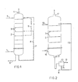
- the raw gas is fed through the feed line 1 at the lower end of the tray column 2. It then flows through the trays 3 and enters the head as a purified gas the bottom column 2 through the nozzle 4 again.
- Nutrient solution is fed through the feed line 5 at the top of the column or at other points.
- the discharge of excess sludge and used nutrient solution can take place from the sump through line 6 or from one of the trays 3. Sedimentation and return of the sludge can be provided (not shown).
- Part of the suspension is normally recirculated to the top of the column (circuit 7) or to one of the trays (circuit 8).
- a return 9 can also be provided within the floors.
- the dashed circuits 8 and 9 form a two-stage return.
- Devices for regulating the pH value can be built into the circuits in order to keep the pH value constant.
- the circuits can also be used to even out the biomass concentration and to supply the microorganisms with inorganic nutrient salts, which can be dissolved or in solid form, for example fed into the circuits.
- the concentration of organic substances dissolved in the suspension (food for the microorganisms) and the oxygen can be equalized by external circuits.
- the tray column 2 is used for wastewater treatment.
- the raw waste water is fed to the top floor 3 via the inlet 10 and flows from there successively over the floors 3 to the liquid outlet 11 and from there into the sludge retention device 12. From here, the treated waste water runs through the overflow 13, while the excess sludge flows through the line 14 is removed and return sludge via the circuit 15 to the top Soil 3 is returned.
- the air required for aerobic wastewater treatment is fed through the connector 16 at the bottom of the column 2, flows through the trays 3 in countercurrent to the liquid and emerges again at the top of the column through the discharge connector 17.
- the raw wastewater can also be fed in on a lower ground than the top one.
- the soils above the raw water inlet then serve for biological waste gas purification for volatile waste water constituents, which are otherwise discharged with the air flow that serves to supply oxygen.
- the biological purification of the waste gas resulting from the wastewater treatment can, however, also be carried out in a separate column, which is often useful because of the greatly different liquid loads in the two parts of the plant.
- a division of the exhaust gas and / or wastewater treatment into several columns operated in parallel or in series with respect to the gas flow and / or the liquid flow is also useful in other cases.
- structural reasons (height) or the use of existing equipment (column sections, compressors etc.) also play a role, as does the greater flexibility that is then possible in the event of load fluctuations (switching on when the amount of waste water or exhaust gas increases or the concentration of pollutants to be broken down).
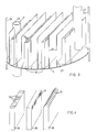
- the structure of the tray 3 is explained in more detail with reference to FIG. 3.
- the gas to be cleaned flows through the channels 18 with a rectangular cross cut (internals) upwards and enters the liquid through the gas outlet openings formed here as holes 19.
- Vertical baffles 20 are arranged between the channels 18. The baffles 20 cause convection flows in the liquid, the liquid flowing upwards in the zones between the gas channels 18 and the baffles 20, releasing the gas escaping from the gas channels 18 at the top, in part thereby flowing laterally over the upper edges of the baffles 20 in the zones between the baffles flow down again and through the gaps 21 directly at the bottom 3 again into the zones between the baffle 20 and gas channel 18.
- This mammoth pump flow running around the guide plates 20 is used for mixing on the trays 3 and for the dispersion of the solids in the liquid (activated sludge!).
- a superimposed cross-flow of the liquid from the inlet pipes 22 or shafts to the outlet pipes 23 also takes place on the floors.
- the seal between the trays 3 and the column wall 24 and the fastening of the trays 3 in the column is known from distillation technology and therefore need not be described in more detail here.
- the gas outlet openings 19 are here as horizontal (left partial image) or vertical slots (middle partial image) or as slot-shaped openings in a roof-shaped closed channel (right partial image). executed.
- Fig. 5 shows a cross section through a floor version with cylindrical gas channels 26, on which bells 27 are fastened, which have slots 19 as gas outlet openings.
- the bells 27 there are concentric guide tubes 28 which leave a gap 29 between the actual base 3 and its lower edge through which the liquid can flow from the liquid zones between the guide tubes 28 and the chimneys 26 or the bells 27.
- the liquid then flows upward, is gassed at the slots 19 and flows over the upper edges of the guide tubes 28 into the zones between the guide tubes and down there again (see flow arrows).
- the liquid flows through the pipe 22 to the bottom and from the upper edge into the pipe 23 again.
- this wall cover can be rinsed off particularly easily by free spraying, as shown in FIG. 6, flushing pipes 30 with spray openings 31 or spray nozzles are introduced perpendicularly to the channels 18 into the gas space beneath the corresponding trays 3 and the gas rise channels are sprayed free if necessary or washed away.
- the number of pipes required can be kept particularly small if they are arranged so that they can be rotated about their longitudinal axis, so that a relatively large channel length can be covered by rotating each spray opening or nozzle.
- the spray openings 31 are each under the gas riser channels 18, so that through Rotation of the flushing pipes running perpendicular to the longitudinal direction of the gas channels allows the entire inside of the gas channels to be sprayed or flushed out.
- correspondingly more pipes are arranged in parallel, the spacing of which depends on the spray width of the nozzles or spray openings 31, which in turn depends on the geometry (channel heights, pipe and spray opening diameter) and on the admission pressure of the flushing liquid.
Abstract
Description
Die Erfindung betrifft ein Verfahren zur biologischen Abgas- oder Abwasserreinigung, bei dem das Abgas bzw. das Abwasser durch einen Gas-Flüssigkeitskontaktapparat geleitet wird. Ferner betrifft die Erfindung eine Vorrichtung zur Durchführung des Verfahrens.The invention relates to a method for biological waste gas or waste water purification, in which the waste gas or waste water is passed through a gas-liquid contact apparatus. The invention further relates to a device for carrying out the method.
An Biowäscher bzw. Biofilter für die biologische Abluftreinigung werden folgende Anforderungen gestellt:
- 1. Hohe Wirksamkeit, d.h. möglichst vollständige Entfernung von Schad- bzw. Geruchsstoffen aus der Abluft:
- 2. Kleine Abmessungen, insbesondere kleine Querschnittsfläche (Platzbedarf):
- 3. Geringer Energieaufwand (Betriebskosten):
- 4. Einfacher Aufbau und Betrieb:
- 5. Wirksamkeit für eine möglichst breite Palette von Schadstoffen in möglichst großen Konzentrationsbereichen.
- 1. High effectiveness, ie complete removal of harmful or odorous substances from the exhaust air:
- 2. Small dimensions, especially small cross-sectional area (space requirement):
- 3. Low energy consumption (operating costs):
- 4. Simple construction and operation:
- 5. Efficacy for the widest possible range of pollutants in the largest possible concentration ranges.
Besonders schwierig wird die Erfüllung dieser Anforderungen, wenn wegen hohen Schadstoffgehalts der Abluft und des damit meist verbundenen hohen Sauerstoffbedarfs für den biologischen Abbau oder wegen geringer Wasserlöslichkeit der zu entfernenden Komponenten hohe Anforderungen an die Stoffaustauschleistung gestellt werden.It becomes particularly difficult to meet these requirements if, due to the high pollutant content in the exhaust air and the associated high oxygen demand for biodegradation or due to the low water solubility of the components to be removed, high demands are placed on the mass transfer performance.
Bei einer detaillierten Untersuchung der bekannten Biowäscher bzw. Biofilter stellt man fest, daß alle in zumindest einem, meist aber hinsichtlich mehrerer der oben aufgeführten Kriterien erhebliche Mängel aufweisen.A detailed examination of the known bio-washers or bio-filters reveals that all of them have significant defects in at least one, but mostly with regard to several of the criteria listed above.
Praktisch alle Biofilter können nur bei geringen Gasgeschwindigkeiten (-0,1 m/s oder darunter) betrieben werden und erfordern daher große Flächen. Bei hohem Schadstoffgehalt und damit verbundenem hohen Biomassewachstum neigen sie zum Zuwachsen. Entstehen beim biologischen Abbau starke Säuren (HCl, HF, H₂SO₄ oder HNO₃) wie z.B. beim Abbau von halogenierten Kohlenwasserstoffen bzw. verschiedenen Schwefel- oder Stickstoffverbindungen, so sinkt der pH-Wert in den Biofiltern (z.B. Kompostfiltern) und die biologische Abbauleistung kommt zum Stillstand, wenn man nicht durch Basenzugabe eine pH-Regelung durchführt, was den Druckverlust erhöht und Maldistributionsprobleme (Flüssigkeitsrandgängigkeit bei Gegenstrom) oder Wirksam keitsverluste (Flüssigkeit schleppt Schadstoff mit!) mit sich bringt.Practically all biofilters can only be operated at low gas speeds (-0.1 m / s or less) and therefore require large areas. With a high pollutant content and the associated high biomass growth, they tend to grow. If strong acids (HCl, HF, H₂SO₄ or HNO₃) arise during biodegradation, such as during the degradation of halogenated hydrocarbons or various sulfur or nitrogen compounds, the pH value in the biofilters (e.g. compost filters) drops and the biodegradation rate comes to a standstill , if one does not carry out a pH control by adding base, which increases the pressure loss and maldistribution problems (liquid fringing in countercurrent) or effective losses (liquid carries along pollutant!).
Die bekannten Biowäscher, z.B. Düsenwäscher, Füllkörper- oder konventionelle Bodenkolonnen (siehe z.B. Jap. Pat. Anmeldung No. 51-67048) mit nachgeschaltetem Bioreaktor weisen als Hauptnachteil den zum Transport von gelösten Schadstoffen und gelöstem Sauerstoff meist erforderlichen extrem großen Flüssigkeitsstrom vom Wäscher zum Bioreaktor und zurück auf. Dieser Nachteil läßt sich zwar durch Zugabe von Sorbentien (z.B. Aktivkohle) verringern; diese Maßnahmen bringen aber neue Nachteile (Abrasion, Unterhaltungs- und Investitionskosten für Kohlebunkerung und Entsorgung) mit sich.The known bio-washers, e.g. Nozzle scrubbers, packed columns or conventional tray columns (see e.g. Japanese Pat. Application No. 51-67048) with a downstream bioreactor have the main disadvantage of the extremely large liquid flow from the scrubber to the bioreactor and back, which is usually required to transport dissolved pollutants and dissolved oxygen. This disadvantage can be reduced by adding sorbents (e.g. activated carbon); however, these measures entail new disadvantages (abrasion, maintenance and investment costs for coal bunkering and disposal).
Als weiterer Nachteil im Falle der Düsenwäscher erweist sich die steigende Komplexität der Anlage, wenn geringe Löslichkeit der Schadstoffe und/oder geringe zulässige Endkonzentration eine mehrstufige Ausführung erforderlich machen.A further disadvantage in the case of the nozzle washer is the increasing complexity of the system when low solubility of the pollutants and / or low permissible final concentration make a multi-stage design necessary.
Hier setzt die Erfindung an. Es lag die Aufgabe zugrunde, ein Verfahren mit den dazugehörigen Apparaturen zur biologischen Abluft- und Abwasserreinigung zu entwickeln, das die auf Seite 1 angegebenen Forderungen möglichst kompromißlos erfüllt.This is where the invention comes in. The task was to develop a process with the associated equipment for biological waste air and waste water purification, which meets the requirements given on
Diese Aufgabe wird erfindungsgemäß dadurch gelöst, daß als Gas-Flüssigkeitskontaktapparat eine Bodenkolonne verwendet wird und die zum biologischen Abbau benötigte Biomasse in der Flüssigkeit suspendiert wird und daß durch an sich bekannte Ablaufwehre oder Ablaufrohre gewährleistet wird, daß sich im Betrieb ein Flüssigkeits-Holdup pro Boden von mehr als 0,07 m³, vorzugsweise mehr als 0,15 m³ pro m² Kolonnenquerschnitt einstellt. Unter einer Bodenkolonne soll hier eine Kolonne mit mindestens zwei Böden verstanden werden, auf denen sich eine zumindest teilweise begaste, d.h. von dem zu reinigenden Gasstrom durchströmte Flüssigkeit befindet, wobei das Gas durch Öffnungen (Schlitze, Löcher, Ventile) in den Böden oder in mit den Böden verbundenen Einbauten (Glocken, Kamine, Kanäle etc.) austritt und so die Böden und zumindest einen Teil der darauf befindlichen Flüssigkeit nacheinander im Gegenstrom bzw. Kreuz/Gegenstrom zum Gas durchströmt. Im Gegensatz zu den bei Destillation und Absorption üblichen Böden mit einem verhältnismäßig geringen Flüssigkeitsinhalt (Holdup) von maximal 0,05 m³ pro m² Bodenfläche wird bei dem erfindungsgemäßen Verfahren ein großer Holdup angestrebt, um das benötigte Reaktionsvolumen bei nicht allzu großer Bodenzahl zu erreichen. Da andererseits je nach angestrebter Endreinheit des Gases und Löslichkeit und Anfangskonzentration der Schadstoffe für die Absorption der Schadstoffe bzw. des zum aeroben Abbau benötigten Sauerstoffs eine bestimmte Bodenzahl erforderlich ist, wird sich je nach Anwendungsfall ein bestimmter optimaler Flüssigkeits-Holdup pro Boden ergeben, der etwa zwischen 0,07 und 2 m³/m² Bodenfläche liegt.This object is achieved in that a bottom column is used as the gas-liquid contact apparatus and the biomass required for biodegradation in the liquid is suspended and that known weirs or drain pipes ensure that a liquid hold-up per tray of more than 0.07 m³, preferably more than 0.15 m³ per m² column cross-section occurs during operation. A tray column is to be understood here as a column with at least two trays on which there is an at least partially fumigated liquid, that is to say through which the gas stream to be cleaned flows, the gas through openings (slots, holes, valves) in the trays or in with internals connected to the floors (bells, chimneys, channels, etc.) emerge and thus flow through the floors and at least part of the liquid thereon in succession in countercurrent or cross / countercurrent to the gas. In contrast to the soils customary for distillation and absorption with a relatively low liquid content (holdup) of at most 0.05 m³ per m² of soil surface, a large holdup is aimed for in the method according to the invention in order to achieve the required reaction volume with a not too large number of trays. On the other hand, depending on the desired final purity of the gas and solubility and initial concentration of the pollutants for the absorption of the pollutants or the oxygen required for aerobic degradation, a certain number of trays is required, depending on the application, there will be a certain optimal liquid holdup per tray, which is approximately between 0.07 and 2 m³ / m² floor area.
Die bei konventionellen Böden übliche Begasung durch die gesamte Flüssigkeit hindurch führt bei den angestrebten Flüssigkeitshöhen zu hohem Druckverlust der Gasströmung und damit zu großem Energieverbrauch. Vorteilhaft wird dieses Problem dadurch gelöst, daß nur ein Teil der Flüssigkeit begast wird, indem das Gas durch mit dem Boden verbundene Kamine oder Kanäle, die die verschiedensten Formen haben können, durch die untere (unbegaste) Flüssigkeitsschicht geführt wird und erst dann durch Schlitze oder Löcher in den genannten Kaminen oder Kanälen oder in an diesen oder an den Böden oder der Wand befestigten Einbauten (z.B. sog. Glocken) oder beweglichen Einbauten (z.B. sog. Ventilen) in die Flüssigkeit austritt. Die mit dieser Teilbegasung normalerweise verbundenen Nachteile, der schlechte Stoffaustausch zwischen unbegaster und begaster Flüssigkeit und die Sedimentation von Biomasse im unbegasten Bereich werden entsprechend einer Weiterbildung der Erfindung dadurch vermieden, daß durch im wesentlichen vertikale Einbauten (Leitbleche bzw. Leitrohre), welche den Flüssigkeitsraum in begaste Aufwärtsbewegungszonen und unbegaste Abwärtsbewegungszonen unterteilen, Konvektionsströmungen erzeugt werden. Dazu sind die Leitbleche bzw. Leitrohre so bemessen und angeordnet, daß zwischen Boden und Unterkante der Leitbleche bzw. Leitrohre und zwischen Oberkante derselben und der Flüssigkeitsoberfläche sich ein für die Umströmung ausreichender Zwischenraum befindet. Die Höhe der Flüssigkeit (Gas-Flüssig-Sprudelschicht) wird bestimmt durch die Oberkante der Ablaufrohre bzw. Ablaufschächte sowie die Flüssigkeitsüberhöhung über das Ablaufwehr (analog zu den Verhältnissen bei konventionellen Böden).The gassing that is common in conventional soils through the entire liquid leads to a high pressure loss of the gas flow at the desired liquid heights and thus to high energy consumption. Will be beneficial this problem is solved in that only a part of the liquid is gassed, by the gas is led through chimneys or channels connected to the floor, which can have various forms, through the lower (ungased) liquid layer and only then through slots or holes in the chimneys or ducts mentioned or in fixtures (e.g. so-called bells) or movable fixtures (e.g. so-called valves) attached to these or to the floors or the wall, into the liquid. The disadvantages normally associated with this partial fumigation, the poor mass transfer between ungased and fumigated liquid and the sedimentation of biomass in the ungased area are avoided according to a further development of the invention in that essentially vertical installations (baffles or guide pipes) which separate the liquid space Subdivide fumigated upward movement zones and ungassed downward movement zones, convection currents are generated. For this purpose, the guide plates or guide tubes are dimensioned and arranged such that there is a sufficient space for the flow to flow between the bottom and lower edge of the guide plates or guide tubes and between the upper edge thereof and the liquid surface. The height of the liquid (gas-liquid bubble layer) is determined by the upper edge of the drain pipes or drainage ducts as well as the liquid elevation over the drain weir (analogous to the situation with conventional floors).
Bei der vorzugsweise zu verwendenden Ausführung mit Gasaufstiegskanälen kann eine Spülung der dem Gasraum zuge wandten Innenflächen der Kanäle von anhaftender Biomasse besonders leicht durchgeführt werden, wenn jemals unter den Böden Rohre mit geeignet angebrachten Sprühdüsen und Sprühlöchern senkrecht zu den Kanälen angebracht werden. Diese Rohre sind vorzugsweise um ihre Längsachse drehbar. Dadurch kann der Spüleffekt verbessert werden.In the embodiment with gas riser channels to be used preferably, a flushing of the gas space can be done the inside surfaces of the channels of adhering biomass can be carried out particularly easily if pipes with suitable spray nozzles and spray holes are ever installed under the floors perpendicular to the channels. These tubes are preferably rotatable about their longitudinal axis. This can improve the rinsing effect.
Der entscheidende Unterschied des erfindungsgemäßen Verfahrens gegenüber einem konventionellen Biowäscher besteht darin, daß der größte Teil des zum Bioabbau benötigten Volumens in der Bodenkolonne untergebracht werden kann (integrierte Absorber/Bioreaktor). Bei Bedarf können jedoch noch zusätzlich Nachreaktoren (z.B. Pumpenvorlagen) in die externen Flüssigkeitskreisläufe eingeschaltet werden.The decisive difference of the method according to the invention compared to a conventional bio-washer is that most of the volume required for biodegradation can be accommodated in the bottom column (integrated absorber / bioreactor). If required, however, additional post-reactors (e.g. pump templates) can be switched on in the external liquid circuits.
Es hat sich gezeigt, daß mit einer erfindungsgemäßen Biowäscherkolonne DN 450 mm mit einem Gesamtflüssigkeitsinhalt von 0,9 m³, verteilt auf 10 Böden bei einem Druckverlust von ca. 0,1 bar ein Gasstrom von 300 m³/h, beladen mit verschiedenen organischen Schadstoffen, deren Konzentration im Bereich von 100 mg C/m³ bis 4000 mg C/m³ variierte, weitgehend gereinigt werden konnte, wobei Biomassekonzentrationen bis zu 15 g Trockensubstanz/L in der Suspension gehalten werden konnten. Verstopfungen im Flüssigkeitsbereich traten nicht auf. Gelegentliche Verstopfungen im Innern der Gaskanäle konnten am Ansteigen des Druckverlustes erkannt und mit der oben beschriebenen Spülvorrichtung leicht beseitigt werden. Die Betriebskosten lagen weit unter denen von anderen Abgasbehandlungsverfahren.It has been shown that with a DN 450 mm bio-washing column according to the invention with a total liquid content of 0.9 m³, distributed over 10 trays with a pressure loss of approx. 0.1 bar, a gas flow of 300 m³ / h, loaded with various organic pollutants, whose concentration varied in the range from 100 mg C / m³ to 4000 mg C / m³, could be largely cleaned, whereby biomass concentrations of up to 15 g dry substance / L could be kept in the suspension. There were no blockages in the fluid area. Occasional blockages inside the gas channels could be recognized by the increase in pressure loss and easily removed with the flushing device described above. The operating costs were far below those of other exhaust gas treatment processes.
So betragen z.B die Energiekosten (überwiegend für die Gasförderung) weit weniger als 1/10 der Energiekosten (überwiegend für die Flüssigkeitsförderung) einer gleich wirksamen mehrstufigen biologischen Düsenwäscheranlage, wenn schlecht wasserlösliche Substanzen (z.B. Toluol) ausgewaschen werden müssen.For example, the energy costs (mainly for gas production) are far less than 1/10 of the energy costs (mainly for liquid production) of an equally effective multi-stage biological nozzle washer system if poorly water-soluble substances (e.g. toluene) have to be washed out.
Weiterhin hat sich gezeigt, daß mit dem erfindungsgemäßen Bioreaktor auch Abwasserströme vorteilhaft biologisch gereinigt werden können. Zu diesem Zweck wird das zu reinigende Abwasser durch die Bodenkolonne geleitet und von Luft, Sauerstoff oder sauerstoffhaltigem Gas durchströmt. Gleichzeitig wird ein Teil der Biomasse vom gereinigten Abwasser abgetrennt und ins zuströmende Abwasser oder in die Kolonne zurückgeführt. Dieses Verfahren ist insbesondere für hochbelastete Abwässer geeignet, vor allem dann, wenn eine extrem platzsparende Bauweise wichtig ist.Furthermore, it has been shown that wastewater streams can also advantageously be biologically cleaned with the bioreactor according to the invention. For this purpose, the wastewater to be cleaned is passed through the tray column and air, oxygen or oxygen-containing gas flows through it. At the same time, part of the biomass is separated from the cleaned wastewater and returned to the inflowing wastewater or the column. This process is particularly suitable for highly contaminated wastewater, especially when an extremely space-saving design is important.
Wegen des im Vergleich zu konventionellen Anlagen hohen möglichen Luftdurchsatzes pro Fläche (über 1 m/s Leerrohrgeschwindigkeit) lassen sich sehr hohe Lufteintragsraten bei relativ geringem Energieaufwand erzielen. Bei den dann erzielbaren hohen Biomassekonzentrationen ergibt sich eine sehr kompakte Anlage. Je nach Schaltung von externen Kreisläufen läßt sich das Verweilzeitspektrum beeinflussen und - falls erwünscht - eine mehrstufige biologische Kläranlage in einem einzigen Apparat realisieren. Wegen der im Vergleich zur Abgasbehandlung großen Flüssigkeitsdurchsätze sind hier die bei Destillationsbodenkolonnen in diesem Fall üblichen Maßnahmen zu treffen (große Schächte, evtl. mehrflutige Böden). Die Belebt schlammabtrennung kann wie in konventionellen Kläranlagen in Eindickern erfolgen. Um jedoch einen Hauptvorteil der erfindungsgemäßen Anlage, den geringen Platzbedarf, nicht aufzugeben, sind kompaktere Trenneinrichtungen, z.B. Flotationszellen, vorzuziehen.Because of the high possible air throughput per area compared to conventional systems (over 1 m / s empty pipe speed), very high air entry rates can be achieved with relatively little energy consumption. The high biomass concentrations that can then be achieved result in a very compact system. Depending on the switching of external circuits, the residence time spectrum can be influenced and - if desired - a multi-stage biological sewage treatment plant can be realized in a single device. Because of the large liquid throughputs compared to the flue gas treatment, the usual measures for distillation tray columns in this case must be taken (large shafts, possibly multi-flow trays). The animated sludge separation can take place in thickeners as in conventional sewage treatment plants. However, in order not to give up a main advantage of the plant according to the invention, the small space requirement, more compact separation devices, for example flotation cells, are preferred.
Im folgenden werden Ausführungsbeispiele der Erfindung anhand einer Zeichnung näher erläutert. Es zeigen
- Fig. 1 ein Prinzipfließbild des erfindungsgemäßen Bioreaktors zur biologischen Abgasreinigung
- Fig. 2 ein Prinzipfließbild des Bioreaktors zur Abwasserreinigung
- Fig. 3 einen Boden des Bioreaktors mit Einbauten für die Einleitung des Abgases in die Flüssigkeit
- Fig. 4 verschiedene Ausführungen der Einbauten mit Gasaustrittsöffnungen und
- Fig. 5 einen schematischen Schnitt durch einen Boden mit zylindrischen Gaskaminen
- Fig. 6 eine schematische Darstellung (perspektivischer Schnitt) durch einen Boden mit Sprührohren.
- Fig. 1 is a schematic flow diagram of the bioreactor according to the invention for biological exhaust gas purification
- Fig. 2 is a schematic flow diagram of the bioreactor for wastewater treatment
- Fig. 3 shows a bottom of the bioreactor with internals for the introduction of the exhaust gas into the liquid
- Fig. 4 different versions of the internals with gas outlet openings and
- Fig. 5 is a schematic section through a floor with cylindrical gas fireplaces
- Fig. 6 is a schematic representation (perspective section) through a floor with spray pipes.
Gemäß Fig. 1 wird das Rohgas durch die Zuleitung 1 am unteren Ende der Bodenkolonne 2 zugeführt. Es strömt dann durch die Böden 3 und tritt als gereinigtes Gas am Kopf der Bodenkolonne 2 durch den Stutzen 4 wieder aus. Nährlösung wird durch die Zuleitung 5 am Kopf der Kolonne oder an anderen Stellen eingespeist. Der Ablauf von Überschußschlamm und verbrauchter Nährlösung kann aus dem Sumpf durch die Leitung 6 oder von einem der Böden 3 erfolgen. Dabei kann eine Sedimentation und Rückführung des Schlammes vorgesehen werden (nicht gezeigt). Ein Teil der Suspension wird normalerweise zum Kopf der Kolonne (Kreislauf 7) oder zu einem der Böden (Kreislauf 8) rezirkuliert. Auch innerhalb der Böden kann eine Rückführung 9 vorgesehen werden. Die gestrichelten Kreisläufe 8 und 9 bilden hier eine zweistufige Rückführung. In die Kreisläufe können Vorrichtungen zur Regelung des pH-Wertes eingebaut werden, um den pH-Wert konstant zu halten. Die Kreisläufe können auch zur Vergleichmäßigung der Biomassekonzentration und zur Versorgung der Mikroorganismen mit anorganischen Nährsalzen dienen, welche gelöst oder in fester Form, beispielsweise in die Kreisläufe eingespeist werden können. In Grenzen läßt sich durch externe Kreisläufe auch eine Vergleichmäßigung der Konzentration von in der Suspension gelösten organischen Stoffen (Nahrung für die Mikroorganismen) und des Sauerstoffs erreichen.1, the raw gas is fed through the
Gemäß Fig. 2 wird die Bodenkolonne 2 zur Abwasserreinigung verwendet. Das Rohabwasser wird über den Zulauf 10 dem obersten Boden 3 zugeführt und strömt von dort sukzessive über die Böden 3 zum Flüssigkeitsablauf 11 und von da in die Schlammrückhalteeinrichtung 12. Von hier läuft das geklärte Abwasser durch den Überlauf 13 ab, während der Überschußschlamm durch die Leitung 14 entnommen wird und Rücklaufschlamm über den Kreislauf 15 auf den obersten Boden 3 zurückgeführt wird. Die zur aeroben Abwasserbehandlung erforderliche Luft wird durch den Stutzen 16 am Boden der Kolonne 2 zugeführt, durchströmt im Gegenstrom zur Flüssigkeit die Böden 3 und tritt am Kopf der Kolonne durch den Abzugsstutzen 17 wieder aus.2, the
Abweichend von Fig. 2 kann die Zuspeisung des Rohabwassers auch auf einem mit tieferen Boden als dem obersten erfolgen. Die Böden über dem Rohwasserzulauf dienen dann der biologischen Abgasreinigung für flüchtige Abwasserinhaltsstoffe, welche sonst mit dem der Sauerstoffversorgung dienenden Luftstrom ausgetragen werden.Deviating from FIG. 2, the raw wastewater can also be fed in on a lower ground than the top one. The soils above the raw water inlet then serve for biological waste gas purification for volatile waste water constituents, which are otherwise discharged with the air flow that serves to supply oxygen.
Die biologische Reinigung des bei der Abwasserbehandlung anfallenden Abgases kann jedoch auch in einer separaten Kolonne erfolgen, was wegen der stark unterschiedlichen Flüssigkeitsbelastung der beiden Anlagenteile häufig sinnvoll ist. Eine Aufteilung der Abgas- und/oder Abwasserbehandlung auf mehrere bezüglich der Gasströmung und/oder der Flüssigkeitsströmung parallel oder in Reihe betriebener Kolonnen ist aber auch in anderen Fällen sinnvoll. So können z.B. bauliche Gründe (Bauhöhe) oder die Nutzung bereits vorhandener Apparate (Kolonnenschüsse, Verdichter etc.) ebenso eine Rolle spielen wie die dann mögliche größere Flexibilität bei Belastungsschwankungen (Zuschalten bei Vergrößerung des Abwasser- bzw. Abgasanfalls oder der Konzentration von abzubauenden Schadstoffen).The biological purification of the waste gas resulting from the wastewater treatment can, however, also be carried out in a separate column, which is often useful because of the greatly different liquid loads in the two parts of the plant. A division of the exhaust gas and / or wastewater treatment into several columns operated in parallel or in series with respect to the gas flow and / or the liquid flow is also useful in other cases. For example, structural reasons (height) or the use of existing equipment (column sections, compressors etc.) also play a role, as does the greater flexibility that is then possible in the event of load fluctuations (switching on when the amount of waste water or exhaust gas increases or the concentration of pollutants to be broken down).
Anhand von Fig. 3 wird der Aufbau des Kolonnenbodens 3 genauer erläutert. Das zu reinigende (Zuleitung 1 in Fig. 1) Gas strömt durch die Kanäle 18 mit rechteckigem Quer schnitt (Einbauten) nach oben und tritt durch die hier als Löcher 19 ausgebildeten Gasaustrittsöffnungen in die Flüssigkeit ein. Zwischen den Kanälen 18 sind vertikale Leitbleche 20 angeordnet. Die Leitbleche 20 bewirken Konvektionsströmungen in der Flüssigkeit, wobei die Flüssigkeit in den Zonen zwischen den Gaskanälen 18 und den Leitblechen 20 nach oben strömt, oben das aus den Gaskanälen 18 ausgetretene Gas freisetzt, zum Teil dabei seitlich über die Oberkanten der Leitbleche 20 strömt, in den Zonen zwischen den Leitblechen wieder abwärts strömt und durch die Spalte 21 unmittelbar am Boden 3 wieder in die Zonen zwischen Leitblech 20 und Gaskanal 18 eintritt. Diese um die Leitbleche 20 herum verlaufende Mammutpumpenströmung dient der Vermischung auf den Böden 3 und der Dispergierung der Feststoffe in der Flüssigkeit (Belebtschlamm!). Daneben findet auf den Böden noch eine überlagerte Querströmung der Flüssigkeit von den Zulaufrohren 22 oder Schächten zu den Ablaufrohren 23 statt. Die Abdichtung zwischen den Böden 3 und der Kolonnenwand 24 sowie die Befestigung der Böden 3 in der Kolonne ist aus der Destillationstechnik bekannt und braucht daher hier nicht näher beschrieben zu werden.The structure of the
Fig. 4 zeigt verschiedene Ausführungen für die Gasaustrittsöffnungen am oberen Ende der quaderförmigen Kanäle 18. Die Gasaustrittsöffnungen 19 sind hier als horizontal (linkes Teilbild) bzw. vertikal verlaufende Schlitze (mittleres Teilbild) oder als schlitzförmige Öffnungen in einem dachförmig abgeschlossenen Kanal (rechtes Teilbild) ausgeführt.4 shows different designs for the gas outlet openings at the upper end of the
Fig. 5 zeigt einen Querschnitt durch eine Bodenausführung mit zylindrischen Gaskanälen 26, auf denen Glocken 27 befestigt sind, die Schlitze 19 als Gasaustrittsöffnungen aufweisen. Um die Glocken 27 herum sind konzentrische Leitrohre 28 angeordnet, die zwischen dem eigentlichen Boden 3 und ihrer Unterkante einen Spalt 29 freilassen, durch den die Flüssigkeit aus den Flüssigkeitszonen zwischen den Leitrohren 28 und den Kaminen 26 bzw. den Glocken 27 strömen kann. Die Flüssigkeit strömt dann aufwärts, wird an den Schlitzen 19 begast und strömt über die Oberkanten der Leitrohre 28 in die Zonen zwischen den Leitrohren und dort wieder abwärts (siehe Strömungspfeile). Wie bei der Ausführung nach Fig. 3, strömt die Flüssigkeit durch das Rohr 22 dem Boden zu und am oberen Rand in das Rohr 23 wieder ab. Bei Dauerbetrieb kann in den Gasausstiegskanälen 18 oder Kaminen 26 und Glocken 27 Wandbewuchs durch Mikroorganismen auftreten, welches im Extremfall zu einem Verstopfen dieser der Gasführung dienenden Teile führen kann. Bei der vorzugsweise gewählten Ausführung mit Kanälen läßt sich dieser Wandbewuchs durch Freisprühen besonders einfach Abspülen, indem gemäß Fig. 6 Spülrohre 30 mit Sprühöffnungen 31 oder Sprühdüsen senkrecht zu den Kanälen 18 in den Gasraum unter den entsprechenden Böden 3 eingebracht werden und die Gasaufstiegskanäle bei Bedarf freigesprüht bzw. freigespült werden. Die Anzahl der benötigten Rohre kann besonders klein gehalten werden, wenn man diese um ihre Längsachse drehbar anordnet, so daß durch Drehen pro Sprühöffnung oder -düse eine relativ große Kanallänge überstrichen werden kann. Die Sprühöffnungen 31 liegen jeweils unter den Gasaufstiegskanälen 18, so daß durch Drehen der senkrecht zur Längsrichtung der Gaskanäle verlaufenden Spülrohre die gesamten Innenseiten der Gaskanäle freigesprüht bzw. freigespült werden können. Bei größeren Kolonnen werden entsprechend mehr Rohre parallel angeordnet, deren Abstand sich nach der Sprühweite der Düsen bzw. Sprühöffnungen 31 richtet, welche wiederum von der Geometrie (Kanalhöhen, Rohr- und Sprühöffnungsdurchmesser) und vom Vordruck der Spülflüssigkeit abhängt.Fig. 5 shows a cross section through a floor version with
Es leuchtet ein, daß die anhand der Fig. 1 bis 6 erläuterten Ausführungsbeispiele vielfältig variiert werden können, ohne den Rahmen der Erfindung zu verlassen.It is obvious that the exemplary embodiments explained with reference to FIGS. 1 to 6 can be varied in many ways without departing from the scope of the invention.
Claims (9)
Priority Applications (1)
| Application Number | Priority Date | Filing Date | Title |
|---|---|---|---|
| AT87108345T ATE64584T1 (en) | 1986-06-20 | 1987-06-10 | PROCESSES FOR BIOLOGICAL EXHAUST AIR AND WASTE WATER PURIFICATION. |
Applications Claiming Priority (2)
| Application Number | Priority Date | Filing Date | Title |
|---|---|---|---|
| DE3620728 | 1986-06-20 | ||
| DE19863620728 DE3620728A1 (en) | 1986-06-20 | 1986-06-20 | DEVICE AND METHOD FOR BIOLOGICAL EXHAUST AIR AND WASTE WATER TREATMENT |
Publications (3)
| Publication Number | Publication Date |
|---|---|
| EP0249861A2 true EP0249861A2 (en) | 1987-12-23 |
| EP0249861A3 EP0249861A3 (en) | 1989-01-11 |
| EP0249861B1 EP0249861B1 (en) | 1991-06-19 |
Family
ID=6303355
Family Applications (1)
| Application Number | Title | Priority Date | Filing Date |
|---|---|---|---|
| EP19870108345 Expired - Lifetime EP0249861B1 (en) | 1986-06-20 | 1987-06-10 | Process for the biological purification of exhaust air and waste water |
Country Status (6)
| Country | Link |
|---|---|
| US (1) | US4869824A (en) |
| EP (1) | EP0249861B1 (en) |
| JP (1) | JP2515552B2 (en) |
| AT (1) | ATE64584T1 (en) |
| DE (2) | DE3620728A1 (en) |
| ES (1) | ES2022837B3 (en) |
Cited By (7)
| Publication number | Priority date | Publication date | Assignee | Title |
|---|---|---|---|---|
| EP0385555A1 (en) * | 1989-02-28 | 1990-09-05 | Tauw Infra Consult B.V. | Apparatus for carrying out a combined air and water purification, and also a method for operating such a purification |
| EP0442157A1 (en) * | 1990-02-14 | 1991-08-21 | Tauw Milieu B.V. | A method for the purification of contaminated water and apparatus for carrying out said method. |
| WO1992022505A1 (en) * | 1991-06-08 | 1992-12-23 | Mesroc Gmbh Vertrieb Technischer Produkte | Fixed-bed reactor for the biological treatment of sewage |
| WO1995024362A1 (en) * | 1994-03-08 | 1995-09-14 | Buck-Werke Gmbh & Co. | Process for purifying and reusing surfactant-containing waste waters |
| WO2007135087A1 (en) * | 2006-05-23 | 2007-11-29 | Otv Sa | Aerating device for a water filtering system with immersed membranes, including a floor provided with means for injecting a gas and at least one pressure balancing system |
| EP2826543A1 (en) * | 2013-07-16 | 2015-01-21 | Vilniaus Gedimino technikos universitetas | A biofilter-adsorber |
| CN112387039A (en) * | 2020-11-29 | 2021-02-23 | 河南基兆建筑工程有限公司 | But tunnel portal is with vertical multi-chamber formula anti fouling device of air reflux |
Families Citing this family (13)
| Publication number | Priority date | Publication date | Assignee | Title |
|---|---|---|---|---|
| US5232676A (en) * | 1990-08-10 | 1993-08-03 | Bayer Aktiengesellschaft | Process for the biological purification of waste air streams |
| DE4127267C2 (en) * | 1991-08-17 | 1994-10-06 | Degussa | Process for biological waste air purification |
| US5387344A (en) * | 1992-11-13 | 1995-02-07 | Monsanto Enviro-Chem Systems, Inc. | Process for treating waste water oxidation ponds to abate malodors |
| EP0630860B1 (en) * | 1993-06-24 | 1997-08-27 | Boc Gases Australia Limited | Method and apparatus for controlled biological treatment of waste water |
| JP3107950B2 (en) * | 1993-07-07 | 2000-11-13 | オルガノ株式会社 | Biological treatment apparatus and water treatment method using the same |
| US5747331A (en) * | 1994-03-16 | 1998-05-05 | Vapo Oy | Process and apparatus for the purification of gases |
| US6019817A (en) * | 1998-02-25 | 2000-02-01 | Agri Microbe Sales, L.C. | System and method for capturing and destroying HAP/VOC substances using microbial degradation |
| EP0960648A1 (en) * | 1998-05-27 | 1999-12-01 | D.I. Wieser-Linhart, Emil A.J. | Process and plant to clean the off-gas of a dryer |
| US6461510B1 (en) | 1999-07-23 | 2002-10-08 | Tennessee Valley Authority | High-efficiency processes for destruction of contaminants |
| US8852924B2 (en) * | 2009-04-02 | 2014-10-07 | Chingoo Research Partnership | Algae photobioreactor |
| CN102849844B (en) * | 2012-10-10 | 2014-12-10 | 南京大学 | Coupling bioreactor and method for simultaneously purifying malodorous gas and waste water by using same |
| CN106110878A (en) * | 2016-08-31 | 2016-11-16 | 北京北林绿源生态技术研究院有限责任公司 | Exhaust purification unit device and waste gas cleaning system |
| CN112620232A (en) * | 2020-12-10 | 2021-04-09 | 华菱安赛乐米塔尔汽车板有限公司 | Process method for reducing scaling of acid regeneration ferrous chloride washing tower filler |
Citations (3)
| Publication number | Priority date | Publication date | Assignee | Title |
|---|---|---|---|---|
| DE1542274A1 (en) * | 1966-07-06 | 1970-03-26 | Koppers Gmbh Heinrich | Method and device for carrying out slow chemical reactions of gases with liquids |
| DE2334107A1 (en) * | 1973-07-04 | 1975-01-23 | Siemens Ag | Sintered perforated plate column - for activated sludge effluent treatment |
| DE2554169A1 (en) * | 1975-12-02 | 1976-12-09 | Menzel & Co | Treating liq. organic waste aerobically - by heat exchange with oxygen carrier in several stages |
Family Cites Families (18)
| Publication number | Priority date | Publication date | Assignee | Title |
|---|---|---|---|---|
| US2600710A (en) * | 1947-11-15 | 1952-06-17 | Henry N Wade | Bubble cap for washing gases and vapors |
| US3070359A (en) * | 1958-05-29 | 1962-12-25 | Gerard P Canevari | Vapor-liquid contacting apparatus |
| FR1373686A (en) * | 1963-06-10 | 1964-10-02 | Houilleres Bassin Du Nord | Advanced tray for gas-liquid contact columns |
| FR94413E (en) * | 1967-10-26 | 1969-08-14 | Sadoulet Maurice Alfred Alexan | Septic tank effluent purifier. |
| US4100063A (en) * | 1972-07-20 | 1978-07-11 | Maschinenfabrik Hellmut Geiger | Method and apparatus for the biological cleansing of waste water |
| CA1033153A (en) * | 1972-10-12 | 1978-06-20 | Raymond J. Mcgowan | Method and apparatus for heat and mass transfer |
| DE2553050A1 (en) * | 1975-11-26 | 1977-06-16 | Baensch Tetra Werke | EQUIPMENT AND METHOD FOR EXTRACTION OF POLLUTIONS SOLVED IN THE WATER, MAINLY NITRATES |
| JPS53113267A (en) * | 1977-03-15 | 1978-10-03 | Chiyoda Chem Eng & Constr Co Ltd | Gas-liquid contacting apparatus |
| EP0011976A1 (en) * | 1978-11-22 | 1980-06-11 | Geoffrey Gordon Haselden | Distillation plate |
| JPS5816956B2 (en) * | 1979-02-21 | 1983-04-04 | 大和設備工事株式会社 | Combined treatment and purification equipment for sewage liquid |
| US4305895A (en) * | 1979-03-02 | 1981-12-15 | Heath Rodney T | Bubble cap and riser construction |
| US4279842A (en) * | 1979-07-26 | 1981-07-21 | Houston Systems Manufacturing Co., Inc. | Air diffuser assembly |
| FR2473351A1 (en) * | 1980-01-09 | 1981-07-17 | Degremont Sa | DEVICE FOR INTRODUCING GAS IN A LIQUID |
| US4510023A (en) * | 1983-06-17 | 1985-04-09 | Air Products And Chemicals, Inc. | Perforated bubble caps for enhanced vapor/liquid contact on a distillation tray |
| JPS607924A (en) * | 1983-06-28 | 1985-01-16 | Fuji Kasui Kogyo Kk | Treatment of waste gas |
| NL8303031A (en) * | 1983-08-31 | 1985-03-18 | Tongeren Ingbureau Bv Van | METHOD AND APPARATUS FOR BIOLOGICAL FILTRATION OF GASES. |
| FR2557558B1 (en) * | 1984-01-02 | 1986-05-23 | Degremont Sa | UNDERWATER FILTER FILLED WITH GRANULAR MATERIAL |
| DE3412394C1 (en) * | 1984-04-03 | 1985-11-07 | Didier-Werke Ag, 6200 Wiesbaden | Process and apparatus for cleaning aeration tubes |
-
1986
- 1986-06-20 DE DE19863620728 patent/DE3620728A1/en not_active Withdrawn
-
1987
- 1987-06-10 DE DE8787108345T patent/DE3770877D1/en not_active Expired - Lifetime
- 1987-06-10 EP EP19870108345 patent/EP0249861B1/en not_active Expired - Lifetime
- 1987-06-10 AT AT87108345T patent/ATE64584T1/en active
- 1987-06-10 ES ES87108345T patent/ES2022837B3/en not_active Expired - Lifetime
- 1987-06-18 JP JP15037387A patent/JP2515552B2/en not_active Expired - Lifetime
-
1988
- 1988-12-08 US US07/283,008 patent/US4869824A/en not_active Expired - Fee Related
Patent Citations (3)
| Publication number | Priority date | Publication date | Assignee | Title |
|---|---|---|---|---|
| DE1542274A1 (en) * | 1966-07-06 | 1970-03-26 | Koppers Gmbh Heinrich | Method and device for carrying out slow chemical reactions of gases with liquids |
| DE2334107A1 (en) * | 1973-07-04 | 1975-01-23 | Siemens Ag | Sintered perforated plate column - for activated sludge effluent treatment |
| DE2554169A1 (en) * | 1975-12-02 | 1976-12-09 | Menzel & Co | Treating liq. organic waste aerobically - by heat exchange with oxygen carrier in several stages |
Cited By (8)
| Publication number | Priority date | Publication date | Assignee | Title |
|---|---|---|---|---|
| EP0385555A1 (en) * | 1989-02-28 | 1990-09-05 | Tauw Infra Consult B.V. | Apparatus for carrying out a combined air and water purification, and also a method for operating such a purification |
| EP0442157A1 (en) * | 1990-02-14 | 1991-08-21 | Tauw Milieu B.V. | A method for the purification of contaminated water and apparatus for carrying out said method. |
| WO1992022505A1 (en) * | 1991-06-08 | 1992-12-23 | Mesroc Gmbh Vertrieb Technischer Produkte | Fixed-bed reactor for the biological treatment of sewage |
| WO1995024362A1 (en) * | 1994-03-08 | 1995-09-14 | Buck-Werke Gmbh & Co. | Process for purifying and reusing surfactant-containing waste waters |
| WO2007135087A1 (en) * | 2006-05-23 | 2007-11-29 | Otv Sa | Aerating device for a water filtering system with immersed membranes, including a floor provided with means for injecting a gas and at least one pressure balancing system |
| EP2826543A1 (en) * | 2013-07-16 | 2015-01-21 | Vilniaus Gedimino technikos universitetas | A biofilter-adsorber |
| CN112387039A (en) * | 2020-11-29 | 2021-02-23 | 河南基兆建筑工程有限公司 | But tunnel portal is with vertical multi-chamber formula anti fouling device of air reflux |
| CN112387039B (en) * | 2020-11-29 | 2022-09-09 | 河南基兆建筑工程有限公司 | But tunnel portal is with vertical multi-chamber formula antifouling device of air reflux |
Also Published As
| Publication number | Publication date |
|---|---|
| JP2515552B2 (en) | 1996-07-10 |
| ES2022837B3 (en) | 1991-12-16 |
| US4869824A (en) | 1989-09-26 |
| ATE64584T1 (en) | 1991-07-15 |
| EP0249861B1 (en) | 1991-06-19 |
| JPS634831A (en) | 1988-01-09 |
| DE3770877D1 (en) | 1991-07-25 |
| DE3620728A1 (en) | 1987-12-23 |
| EP0249861A3 (en) | 1989-01-11 |
Similar Documents
| Publication | Publication Date | Title |
|---|---|---|
| EP0249861B1 (en) | Process for the biological purification of exhaust air and waste water | |
| EP0306053B1 (en) | Reactor and process for the biological purification of polluted water | |
| DE102006053910B4 (en) | bioscrubber | |
| DE102007050904B4 (en) | Plant and process for the purification of flue gases | |
| DE2705903A1 (en) | HORIZONTAL GAS SPRAY CLEANING DEVICE | |
| EP0355022A1 (en) | Apparatus and process for microbiological water treatment | |
| DE19516660C2 (en) | Process and device with gas-coated sieve plate for wet desulfurization of flue gas | |
| EP0328758B1 (en) | Process and device for the biological cleaning of waste gas | |
| DE3427448A1 (en) | METHOD AND DEVICE FOR BIOLOGICAL WASTE WATER TREATMENT | |
| EP0094573B1 (en) | Device for the purification of exhaust air | |
| EP0470468B1 (en) | Process for the biological cleaning of exhaust air | |
| EP1328332B1 (en) | Exhaust gas purification system | |
| DE3503723C2 (en) | ||
| DE3126078C2 (en) | Device for wastewater purification | |
| EP0902761B1 (en) | Clarification plant for water purification | |
| DE19631796A1 (en) | Biological purification for treating sewage | |
| EP0739860A1 (en) | Process and apparatus for the biological treatment of waste water | |
| EP0162121B1 (en) | Clarifier for the biological purification of waste water | |
| EP0161520B1 (en) | Process and apparatus for the desulfurization of fumes | |
| EP1670723B1 (en) | Method for biologically purifying waste water | |
| DE4240062C1 (en) | Partitioned fixed bed reactor - for odour-free biological waste water treatment | |
| AT409724B (en) | Exhaust gas cleaning assembly has at least two successive filter stages, using spray scrubber or wet electro-filter and biological filter with temperature control | |
| EP0162831A1 (en) | Apparatus for waste water treatment | |
| DE3244962C1 (en) | Process and device for waste water purification | |
| EP0226715A2 (en) | Process and apparatus for the biological denitrification of water |
Legal Events
| Date | Code | Title | Description |
|---|---|---|---|
| PUAI | Public reference made under article 153(3) epc to a published international application that has entered the european phase |
Free format text: ORIGINAL CODE: 0009012 |
|
| 17P | Request for examination filed |
Effective date: 19870610 |
|
| AK | Designated contracting states |
Kind code of ref document: A2 Designated state(s): AT BE CH DE ES FR GB IT LI NL SE |
|
| RIN1 | Information on inventor provided before grant (corrected) |
Inventor name: BARTH, OTTO Inventor name: STRACKE, HUBERT, DR. Inventor name: MELIN, THOMAS, DR. |
|
| PUAL | Search report despatched |
Free format text: ORIGINAL CODE: 0009013 |
|
| AK | Designated contracting states |
Kind code of ref document: A3 Designated state(s): AT BE CH DE ES FR GB IT LI NL SE |
|
| 17Q | First examination report despatched |
Effective date: 19890908 |
|
| GRAA | (expected) grant |
Free format text: ORIGINAL CODE: 0009210 |
|
| AK | Designated contracting states |
Kind code of ref document: B1 Designated state(s): AT BE CH DE ES FR GB IT LI NL SE |
|
| REF | Corresponds to: |
Ref document number: 64584 Country of ref document: AT Date of ref document: 19910715 Kind code of ref document: T |
|
| ITF | It: translation for a ep patent filed |
Owner name: ING. C. GREGORJ S.P.A. |
|
| REF | Corresponds to: |
Ref document number: 3770877 Country of ref document: DE Date of ref document: 19910725 |
|
| ET | Fr: translation filed | ||
| GBT | Gb: translation of ep patent filed (gb section 77(6)(a)/1977) | ||
| PLBE | No opposition filed within time limit |
Free format text: ORIGINAL CODE: 0009261 |
|
| STAA | Information on the status of an ep patent application or granted ep patent |
Free format text: STATUS: NO OPPOSITION FILED WITHIN TIME LIMIT |
|
| 26N | No opposition filed | ||
| EAL | Se: european patent in force in sweden |
Ref document number: 87108345.7 |
|
| PGFP | Annual fee paid to national office [announced via postgrant information from national office to epo] |
Ref country code: DE Payment date: 19970516 Year of fee payment: 11 |
|
| PGFP | Annual fee paid to national office [announced via postgrant information from national office to epo] |
Ref country code: SE Payment date: 19970522 Year of fee payment: 11 |
|
| PGFP | Annual fee paid to national office [announced via postgrant information from national office to epo] |
Ref country code: FR Payment date: 19970528 Year of fee payment: 11 |
|
| PGFP | Annual fee paid to national office [announced via postgrant information from national office to epo] |
Ref country code: GB Payment date: 19970602 Year of fee payment: 11 |
|
| PGFP | Annual fee paid to national office [announced via postgrant information from national office to epo] |
Ref country code: ES Payment date: 19970609 Year of fee payment: 11 Ref country code: CH Payment date: 19970609 Year of fee payment: 11 |
|
| PGFP | Annual fee paid to national office [announced via postgrant information from national office to epo] |
Ref country code: AT Payment date: 19970620 Year of fee payment: 11 |
|
| PGFP | Annual fee paid to national office [announced via postgrant information from national office to epo] |
Ref country code: BE Payment date: 19970626 Year of fee payment: 11 |
|
| PGFP | Annual fee paid to national office [announced via postgrant information from national office to epo] |
Ref country code: NL Payment date: 19970630 Year of fee payment: 11 |
|
| PG25 | Lapsed in a contracting state [announced via postgrant information from national office to epo] |
Ref country code: GB Free format text: LAPSE BECAUSE OF NON-PAYMENT OF DUE FEES Effective date: 19980610 Ref country code: AT Free format text: LAPSE BECAUSE OF NON-PAYMENT OF DUE FEES Effective date: 19980610 |
|
| PG25 | Lapsed in a contracting state [announced via postgrant information from national office to epo] |
Ref country code: SE Free format text: LAPSE BECAUSE OF NON-PAYMENT OF DUE FEES Effective date: 19980611 Ref country code: ES Free format text: LAPSE BECAUSE OF NON-PAYMENT OF DUE FEES Effective date: 19980611 |
|
| PG25 | Lapsed in a contracting state [announced via postgrant information from national office to epo] |
Ref country code: LI Free format text: LAPSE BECAUSE OF NON-PAYMENT OF DUE FEES Effective date: 19980630 Ref country code: CH Free format text: LAPSE BECAUSE OF NON-PAYMENT OF DUE FEES Effective date: 19980630 Ref country code: BE Free format text: LAPSE BECAUSE OF NON-PAYMENT OF DUE FEES Effective date: 19980630 |
|
| BERE | Be: lapsed |
Owner name: BAYER A.G. Effective date: 19980630 |
|
| PG25 | Lapsed in a contracting state [announced via postgrant information from national office to epo] |
Ref country code: NL Free format text: LAPSE BECAUSE OF NON-PAYMENT OF DUE FEES Effective date: 19990101 |
|
| GBPC | Gb: european patent ceased through non-payment of renewal fee |
Effective date: 19980610 |
|
| REG | Reference to a national code |
Ref country code: CH Ref legal event code: PL |
|
| PG25 | Lapsed in a contracting state [announced via postgrant information from national office to epo] |
Ref country code: FR Free format text: LAPSE BECAUSE OF NON-PAYMENT OF DUE FEES Effective date: 19990226 |
|
| EUG | Se: european patent has lapsed |
Ref document number: 87108345.7 |
|
| NLV4 | Nl: lapsed or anulled due to non-payment of the annual fee |
Effective date: 19990101 |
|
| PG25 | Lapsed in a contracting state [announced via postgrant information from national office to epo] |
Ref country code: DE Free format text: LAPSE BECAUSE OF NON-PAYMENT OF DUE FEES Effective date: 19990401 |
|
| REG | Reference to a national code |
Ref country code: FR Ref legal event code: ST |
|
| REG | Reference to a national code |
Ref country code: ES Ref legal event code: FD2A Effective date: 20000503 |
|
| PG25 | Lapsed in a contracting state [announced via postgrant information from national office to epo] |
Ref country code: IT Free format text: LAPSE BECAUSE OF NON-PAYMENT OF DUE FEES;WARNING: LAPSES OF ITALIAN PATENTS WITH EFFECTIVE DATE BEFORE 2007 MAY HAVE OCCURRED AT ANY TIME BEFORE 2007. THE CORRECT EFFECTIVE DATE MAY BE DIFFERENT FROM THE ONE RECORDED. Effective date: 20050610 |