EP0902761B1 - Clarification plant for water purification - Google Patents
Clarification plant for water purification Download PDFInfo
- Publication number
- EP0902761B1 EP0902761B1 EP19970926962 EP97926962A EP0902761B1 EP 0902761 B1 EP0902761 B1 EP 0902761B1 EP 19970926962 EP19970926962 EP 19970926962 EP 97926962 A EP97926962 A EP 97926962A EP 0902761 B1 EP0902761 B1 EP 0902761B1
- Authority
- EP
- European Patent Office
- Prior art keywords
- purification
- water
- plant according
- elements
- gassing
- Prior art date
- Legal status (The legal status is an assumption and is not a legal conclusion. Google has not performed a legal analysis and makes no representation as to the accuracy of the status listed.)
- Expired - Lifetime
Links
Images


Classifications
-
- C—CHEMISTRY; METALLURGY
- C02—TREATMENT OF WATER, WASTE WATER, SEWAGE, OR SLUDGE
- C02F—TREATMENT OF WATER, WASTE WATER, SEWAGE, OR SLUDGE
- C02F3/00—Biological treatment of water, waste water, or sewage
- C02F3/02—Aerobic processes
-
- B—PERFORMING OPERATIONS; TRANSPORTING
- B01—PHYSICAL OR CHEMICAL PROCESSES OR APPARATUS IN GENERAL
- B01D—SEPARATION
- B01D21/00—Separation of suspended solid particles from liquids by sedimentation
- B01D21/0006—Settling tanks provided with means for cleaning and maintenance
-
- B—PERFORMING OPERATIONS; TRANSPORTING
- B01—PHYSICAL OR CHEMICAL PROCESSES OR APPARATUS IN GENERAL
- B01D—SEPARATION
- B01D21/00—Separation of suspended solid particles from liquids by sedimentation
- B01D21/24—Feed or discharge mechanisms for settling tanks
- B01D21/245—Discharge mechanisms for the sediments
-
- B—PERFORMING OPERATIONS; TRANSPORTING
- B01—PHYSICAL OR CHEMICAL PROCESSES OR APPARATUS IN GENERAL
- B01D—SEPARATION
- B01D21/00—Separation of suspended solid particles from liquids by sedimentation
- B01D21/24—Feed or discharge mechanisms for settling tanks
- B01D21/2494—Feed or discharge mechanisms for settling tanks provided with means for the removal of gas, e.g. noxious gas, air
-
- B—PERFORMING OPERATIONS; TRANSPORTING
- B01—PHYSICAL OR CHEMICAL PROCESSES OR APPARATUS IN GENERAL
- B01D—SEPARATION
- B01D21/00—Separation of suspended solid particles from liquids by sedimentation
- B01D21/30—Control equipment
- B01D21/34—Controlling the feed distribution; Controlling the liquid level ; Control of process parameters
-
- C—CHEMISTRY; METALLURGY
- C02—TREATMENT OF WATER, WASTE WATER, SEWAGE, OR SLUDGE
- C02F—TREATMENT OF WATER, WASTE WATER, SEWAGE, OR SLUDGE
- C02F3/00—Biological treatment of water, waste water, or sewage
- C02F3/30—Aerobic and anaerobic processes
- C02F3/301—Aerobic and anaerobic treatment in the same reactor
-
- C—CHEMISTRY; METALLURGY
- C02—TREATMENT OF WATER, WASTE WATER, SEWAGE, OR SLUDGE
- C02F—TREATMENT OF WATER, WASTE WATER, SEWAGE, OR SLUDGE
- C02F2209/00—Controlling or monitoring parameters in water treatment
- C02F2209/42—Liquid level
-
- C—CHEMISTRY; METALLURGY
- C02—TREATMENT OF WATER, WASTE WATER, SEWAGE, OR SLUDGE
- C02F—TREATMENT OF WATER, WASTE WATER, SEWAGE, OR SLUDGE
- C02F2301/00—General aspects of water treatment
- C02F2301/02—Fluid flow conditions
- C02F2301/024—Turbulent
-
- C—CHEMISTRY; METALLURGY
- C02—TREATMENT OF WATER, WASTE WATER, SEWAGE, OR SLUDGE
- C02F—TREATMENT OF WATER, WASTE WATER, SEWAGE, OR SLUDGE
- C02F3/00—Biological treatment of water, waste water, or sewage
- C02F3/02—Aerobic processes
- C02F3/12—Activated sludge processes
- C02F3/20—Activated sludge processes using diffusers
-
- Y—GENERAL TAGGING OF NEW TECHNOLOGICAL DEVELOPMENTS; GENERAL TAGGING OF CROSS-SECTIONAL TECHNOLOGIES SPANNING OVER SEVERAL SECTIONS OF THE IPC; TECHNICAL SUBJECTS COVERED BY FORMER USPC CROSS-REFERENCE ART COLLECTIONS [XRACs] AND DIGESTS
- Y02—TECHNOLOGIES OR APPLICATIONS FOR MITIGATION OR ADAPTATION AGAINST CLIMATE CHANGE
- Y02W—CLIMATE CHANGE MITIGATION TECHNOLOGIES RELATED TO WASTEWATER TREATMENT OR WASTE MANAGEMENT
- Y02W10/00—Technologies for wastewater treatment
- Y02W10/10—Biological treatment of water, waste water, or sewage
Definitions
- the present invention relates to a sewage treatment plant for the treatment of water according to the generic term of claim 1.
- Such treatment plants are used for cleaning and processing of water and waste water from industry and households used. It is essential that one if possible complete removal of pollutants takes place and that after treatment, the water has a high oxygen content.
- the main cleaning is mostly caused by biodegradation processes in Microorganisms that targeted the wastewater added or cultivated in the clarifier.
- Waste water according to the respective local statutes for indirect dischargers to a specified COD limit must be pre-cleaned. This cleaning must therefore be used even in confined spaces in the production plants.
- the wastewater be constantly stirred.
- a sedimentation area in which excess suspended matter in the waste water, such as Agglomerations of microorganisms as Sewage sludge to be deposited.
- This area of the Wastewater treatment plant is used as a resting area for the purified water educated. The water that the sedimentation basin is largely removed from the pollutants freed and can be after further oxygenation be released to the environment.
- the sewage treatment plant described has a very high one Space requirement, as for the individual functions of the preliminary clarification, biological cleaning and sedimentation as well as the oxygenation of the clarified Water a separate pool is needed.
- a disadvantage of the reactors according to the prior art is further that for the satisfactory enrichment of the water to be cleaned with oxygen a high air intake is necessary and that these reactors a very high energy consumption for air intake and circulation of the liquid to be cleaned.
- DE 295 02 701 discloses a ventilation device known for wastewater, the two nested Has tubes in a container, the tubes as Riser and downpipe are formed. The thing to be cleaned Water is added to the container and the aerated Drained water. In the lower area of the riser pipe a fumigation device in the form of fumigation stones provided that connected to a compressed air line and is pushed through the air. The riser pipe is arranged with open at the bottom of the container Pipelines connected through the water into the riser to be led.
- the object of the present invention is a sewage treatment plant to provide that high cleaning performance based on volume and time, as well as small dimensions and has low energy consumption. Furthermore, it is an object of the present invention to provide a wastewater treatment plant that is simple and is inexpensive to assemble or disassemble.
- the sewage treatment plant according to the invention consists only of a housing as a liquid container that has a treatment area and encloses a sedimentation area and in a suitable way a fumigation element and one that is positively connected to it Processing element are arranged.
- Waste water treatment plants are therefore unnecessary Conveying and circulation devices of the water to be treated. This leads to a significant reduction in installation and maintenance costs as well as a significantly lower energy consumption of the sewage treatment plant according to the invention.
- By the oxygenation of the water to be treated immediately before swirling the water in the treatment element will continue to be a hitherto hardly possible Achieved oxygen saturation of the water, causing the achievable biodegradation performance of the sewage treatment plant according to the invention is very high.
- the swirl of the water in the treatment element leads to a very fine distribution of the microorganisms floating in the wastewater, since their Agglomeration is severely hampered. It follows a large phase interface between the microorganisms and the pollutant substrate of the to be processed Water, resulting in a very high biodegradation rate the pollutants is achieved.
- the geometry, i.e. Height, width or depth of the invention Sewage treatment plant can be in compliance with the desired volumes of the individual wastewater treatment plant components and in compliance with the desired length of stay chosen arbitrarily in the processing element that several fumigation elements are used, each with any number of processing elements are connected via distributors.
- several arrangements of a gassing element and processing element one above the other in Series can be arranged. So any one can Processing volume in any dimension realize in a simple way.
- a sedimentation area arranged with a biomass drain is equipped so that the produced and deposited biomass, which is for the further Cleaning process is no longer needed, periodically from the sewage treatment plant according to the invention Biomass runoff can be removed.
- the flow rate within the fumigation and of the treatment element can also be a submersible pump be influenced, the suction side is above of the sedimentation area and its pressure side are connected to the inlet of the gassing elements. It is also possible within the fumigation element or the preparation element stirring elements, To attach screw elements or rotor blades, which are driven from the outside and for an additional promotion or swirling of the reprocessed Water.
- the regulation of the filling level of the sewage treatment plant according to the invention with water to be treated can by a Float switches take place.
- the fumigation element, the treatment element and the trickle element of the sewage treatment plant according to the invention can at least partially from the same or similar disc-shaped components assembled be, so that any scalability of the Sewage treatment plant results.
- This is the inventive Sewage treatment plant economical even for the smallest amounts of waste water applicable.
- An adaptation to a changed one Requirement can also be made retrospectively since the Assembly and disassembly of the gassing element and Processing element are very simple. Because of any scalability of the invention Sewage treatment plants can also cover the cost of the treatment Sewage treatment capacity adapted to the needs and be minimized.
- a particularly simple and inexpensive construction the fumigation element, the treatment element and the trickle element results from the use of components that have an outer ring channel and an inner ring channel and several between have webs extending these channels.
- the bridges can in the outer ring and / or the inner ring channel flow into a channel system, about substances like nutrient solutions, Gases or enzymes can be added.
- a such feeding is particularly easy when the elements are made of ceramic and the ceramic is porous Has structure. So there is the fumigation element advantageously from such components, which have an air-permeable, porous structure, so that over the outer ring channel and the webs very much fine air bubbles entered into the water to be treated can be.
- the trickle element can also consist of components with correspondingly shaped webs are built.
- Another advantageous embodiment of the components has one in the center of the inner ring channel Implementation on which is in the axis of the component striking medium wave. At individual components can then use the medium wave be connected to the webs, so that the webs as stirring elements, Screw elements or rotor blades for Generation of a flow can be rotated.
- the center shaft is driven from the outside. This is a particularly simple option that Flow speed in individual treatment elements to regulate individually and independently of each other.
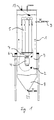
- Fig. 1 shows a sewage treatment plant according to the invention.
- a water inlet 2 for the supply of water to be treated and a water drain 3 as Clear run attached.
- a fumigation element 4 and arranged several processing elements 5, the a distributor 7 are connected to each other.
- a sedimentation area of the gassing element 4 for depositing excess Biomass.
- the area above the sedimentation area 8 is referred to as processing area 9.
- the gassing element 4 is connected to a gas supply line 6 connected via the fumigation element 4 to oxygenate the water to be treated required oxygen or atmospheric air supplied become.
- the Oxygen in the water to be treated largely consumed by the microorganisms.
- the one to be processed Water therefore flows under anoarobic conditions along the outside of the processing elements 5 back to the anaerobic sedimentation area 8.
- the water additionally by anaerobic microorganisms cleaned, for example denitrified. Farther the unwanted is suppressed here Formation of thread bacteria.
- the biomass increases of the microorganisms, so that now in the sedimentation area 8 the excess biomass is deposited becomes. From there it can be fed via a biomass outlet 24 can be removed as sewage sludge.
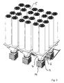
- Fig. 2 shows a sewage treatment plant according to the invention with a total four processing elements. Building this sewage treatment plant according to the invention is essentially same with the sewage treatment plant shown in Fig. 1. Especially it can clearly be seen that the four processing elements 5 via a funnel-shaped distributor are connected to the gassing element 4.
- the fumigation element consists of five disc-shaped components, the total at their peripheral edge four offset from each other at an angle of 90 °, Recesses oriented in the flow direction of the water own, about which the individual components of the Gas supply line 6 oxygen supplied under pressure becomes.
- the four processing elements 5 are disc-shaped Components built that an outer ring channel 15 and an inner ring channel 16 as well as radially have webs 17 extending between these channels. These webs 17 serve to swirl the water to be treated.
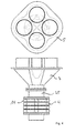
- FIG. 3 shows an arrangement of gassing elements 4, Distributors 7 and processing elements 5 with a total six gassing elements 4 and 24 treatment elements 5. Such a system is also for Suitable for cleaning up large amounts of water.
- Fig. 4 shows in turn a total of four disc-shaped elements 14 fumigation element 4, with its outlet 25 to one Distributor 7 is flanged.
- the distributor ends in a total of four processing elements 7.
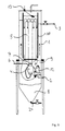
- Fig. 5 shows a sewage treatment plant according to the invention, which is similar is constructed like the sewage treatment plant shown in Fig. 1.
- the same reference numerals designate the same Parts of the sewage treatment plant.
- this sewage treatment plant is the inflow to the clear run 3 of the processing elements 5 separated over a wall 10, so that immediately before the clear run 3 between the housing 1 and the wall 10 results in an additional quiet zone.
- slats directed upwards, for example at 30 ° to wall 10 attached be so that residual suspended matter on these lamellae, that are still in the treated water be deposited. This immediately results an additional residual sedimentation area before clearing 3.
- the inlet of the gassing element 4 is with connected to the pressure side of a suction pump 12, the Suction side in the intermediate area between the sedimentation area 8 and the processing area 9 lies.
- the underwater pump 12 Through the underwater pump 12, the flow rate of the water to be treated through the gassing element 4 and the processing elements 5 additionally can be controlled, which also increases the degree of oxygenation the water in the fumigation element 4 can be influenced.
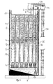
- Fig. 6 shows another example of an inventive Wastewater treatment plant, with the externally accessible Controls arranged above the housing 1 and are accessible via a ladder 30.
- the housing 1 encloses a large number of processing elements 5, the form-fitting at their respective lower end are connected to fumigation elements 4.
- fumigation elements 4 and processing element 5 arranged one above the other and connected to each other in such a way that what is to be purified Water from the respective lower treatment element 5 through one fumigation element 4 into the next Processing element 5 flows.
- the fumigation elements are connected to a compressed air supply 6.
- the lowest fumigation element 4 has another connection, that with the waste water supply line 2 is connected. Through this line 2, the wastewater is immediately in the lowest fumigation element 4 initiated where it started with Oxygen is enriched.
- the supply of waste water is regulated via a float switch 13.
- the pump 28 can, for example over a extending through the housing 1 Chain 36 operated from above the housing 1 become.
- a connecting line 37 Between the sewage sludge line 35 and the waste water supply line 2 is a connecting line 37, via which the wastewater continuously or from time to time with sewage sludge and thus with living Microorganisms can be inoculated.
- the system shown in FIG. 6 is particularly suitable for highly polluted waste water in a small space and with as little energy as possible clean. Due to the stacking of the units from fumigation elements 4 and treatment elements 5 a very long cleaning distance is achieved.
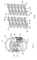
- FIG. 7 shows an arrangement of processing elements according to the invention 5 and fumigation elements 4.
- the Fumigation elements 4 consist of a sequence of disc-shaped components 14.
- the lowest fumigation element 4 consists of six components 14, while the other fumigation elements from the column there are four components each.
- Four each Components of the gassing elements 4 are with a Gas supply line 6 connected.
- In the bottom Fumigation element 4 is a component with a supply line for waste water and another component 14 connected to a sewage sludge supply line. This lowest fumigation element 4 has on his Input a flange 27 with a second Compressed gas supply line is connected.
- Via line 31 is one of the components 14 of the lowest fumigation element 4 waste water in the Interior of the fumigation element initiated.
- About the Line 22 is a further component 14 of the lowest fumigation element 4 sewage sludge the waste water added to this with living microorganisms inoculate for biological cleaning.
- the remaining four components 14 of the gassing element 4 serve to oxygenate the wastewater Supply of atmospheric compressed air or pure oxygen via the gas supply line 6.
- This gas supply line 6 is also with the Components 14 of the further gassing elements 4 connected and ensures a periodic along the column Wastewater aeration.
- the arrangement shown in FIG. 7 can have a sedimentation area and be provided with a housing and then provides a device according to the invention which is characterized by a high cleaning performance the smallest room.
- FIG. 8a shows a component 14 with an outer ring channel 15 and an inner ring channel 16 and between them Channels radially extending webs 17. Furthermore has the component 14 in this example as a whole six axial recesses 18, over which several stacked components 14 together connected or over the one above the other stacked components 14 substances exchanged can be.
- each component 14 are supplied or a gas in the outer ring channels connected to the axial recesses 18 15 and from there in with the outer ring channels connected webs 17 are passed.
- the Webs 17 made of porous, for example ceramic material, this way large quantities can be obtained Gases in a very fine distribution in an inside of the component 14 flowing liquid pressed become.
- Fig. 8a Components shown to build the fumigation element 4 from Fig. 1 can be used.
- the gas supply line 6 is then attached to one of the ends axial recesses 18 of a component stack connected, while the remaining exposed openings the axial recesses 18 are closed.
- oxygen is 6 via the gas supply line or atmospheric air in the axial recesses initiated, this air is distributed over the outer ring channels 15 in the webs 17 and by the porous, ceramic wall of the webs 17 in the water to be treated is pressed.
- FIG. 8b shows a component similar to that in FIG. 8a, the inner ring channel 16 having a passage 19 has that can accommodate a medium wave.
- FIG. 9a shows the structure of a gassing element the components shown in Fig. 8b 14.
- Die Components 14 are stacked and between the individual axial recesses 18 via screw connections 26 screwed together.
- the axial Recesses 18 of the individual components 14 are interconnected while their exposed Ends are closed.
- the gassing element 4 is at both ends each provided a flange 27 so that it is on his Inlet, for example with a submersible pump 12 and at its outlet with a distributor 7 or directly be connected to a processing element 5 can.
- FIG. 9b shows two of the many possibilities for gas routing within the fumigation element 4.
- the components 14 between the individual axial recesses 18 and between the axial recesses and the outer ring channel 15 with breakable Provide seals that are used to generate a specific Flow direction destroyed in a simple way can be.
- the gas is from one axial recess 18 via the webs 17 and Outer ring channels 15 of the opposite recess 18 fed.
- There the gas is within the axial Recess 18 directed to the next component 14, where again there is a change of sides.
- the gas is through an axial recess 18 all components 14 of the gassing element 4 fed and parallel to the opposite axial recesses 18 passed.
- Such an arrangement of components 14 can also selected for the construction of the processing elements 5 be the channel system of the components 14 for example for the supply of enzymes or nutrient solutions used for the liquid to be processed can be.
- a comparison of the bacterial agglomerates shows that the agglomerates in the sewage treatment plant according to the invention are smaller than in a bubble column reactor or in conventional sewage treatment plants, so that there is a larger interface between the microorganisms and the water to be treated, based on the amount of microorganisms, than in conventional sewage treatment technology.
- the 10 shows a further component according to the invention 14, the inner ring 16 with a bushing 19 is provided for a medium wave.
- the webs are run very thin and serve essentially the holder of the inner ring 16.
- Such components 14 can, for example, for storing a Medium wave at the respective ends of the processing elements 5 can be used.
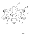
- Fig. 11 shows a rotor element having a central shaft 21 as well as freely rotating on the center shaft 21 Has webs 22 as rotor blades.
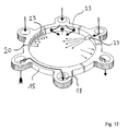
- Fig. 12 shows an injection element as it is used can, for example, to pulse large quantities of gases blow into the fumigation element 4.
- the gas is in turn via axial recesses 18 in passed the outer ring channel 15 and from there via openings 23 into the one flowing inside the injection element Blown in liquid.
- All are shown three different shapes for openings 23, namely slots, round openings and nozzle-shaped radially from the outer ring channel 15 into the inner volume protruding openings.
- Such components can in particular to enter large amounts of gas for an increase the buoyancy of the liquid or for a thorough cleaning of the fumigation elements 4 and Processing elements 5 are used.
- the outer ring channel be interrupted by seals 20 can, so that also several gases and liquids in Packing direction of the components independently of each other are guided over the axial recesses 18 can.
- the different currents are through Arrows shown.
- This component can be used with anyone of the components described are connected.
Abstract
Description
Die vorliegende Erfindung bezieht sich auf ein Klärwerk
zur Aufbereitung von Wasser nach dem Oberbegriff
des Anspruchs 1.The present invention relates to a sewage treatment plant
for the treatment of water according to the generic term
of
Derartige Klärwerke werden zum Reinigen und Aufbereiten von Wässern und Abwässern aus Industrie und Haushalt verwendet. Wesentlich ist dabei, daß eine möglichst vollständige Entfernung von Schadstoffen erfolgt und daß das Wasser nach der Aufbereitung einen hohen Sauerstoffgehalt aufweist. Die Hauptreinigung wird dabei meist durch biologische Abbauprozesse in Mikroorganismen erzielt, die dem Abwasser gezielt zugegeben oder in dem Klärbecken kultiviert werden.Such treatment plants are used for cleaning and processing of water and waste water from industry and households used. It is essential that one if possible complete removal of pollutants takes place and that after treatment, the water has a high oxygen content. The main cleaning is mostly caused by biodegradation processes in Microorganisms that targeted the wastewater added or cultivated in the clarifier.
In Produktionsbetrieben fallen organisch hochbelastete Abwässer an, die nach den jeweiligen Ortssatzungen für Indirekteinleiter auf einen vorgegebenen CSB-Grenzwert vorgereinigt werden müssen. Diese Reinigung muß daher auch unter beengten räumlichen Verhältnissen in den Produktionsbetrieben erfolgen.Organically highly contaminated fall in production plants Waste water according to the respective local statutes for indirect dischargers to a specified COD limit must be pre-cleaned. This cleaning must therefore be used even in confined spaces in the production plants.
Für diesen Zweck werden herkömmliche Klärwerke verwendet, bei denen das aufzubereitende Wasser nacheinander in verschiedene Becken geleitet werden. In einem ersten Becken erfolgt eine mechanische Vorklärung des Wassers, das anschließend in ein Becken zur Belüftung mit Sauerstoff geleitet wird. In diesem Belüftungsbecken wird das Wasser mit reinem Sauerstoff oder mit Luft belüftet und so der Sauerstoffgehalt des Wassers erhöht. In diesem Becken oder auch in einem sich anschließenden Becken vollzieht sich die biologische Reinigungsstufe, bei der mit Hilfe von Mikroorganismen die meisten Schadstoffe des aufzubereitenden Wassers abgebaut werden. Bei diesem Prozeß wird sehr viel Sauerstoff durch die Mikroorganismen verbraucht, so daß eine ständige Sauerstoffzufuhr aufrechterhalten werden muß. Um eine Agglomerierung der Mikroorganismen zu größeren biologischen Verbänden und ein Absetzen dieser Mikroorganismen auf den Grund des Behälters zu verhindern, muß das Abwasser ständig gerührt werden. An das biologische Klärbecken schließt sich eine Sedimentationsbereich an, in dem überschüssige Schwebstoffe des Abwassers, wie beispielsweise Agglomerationen von Mikroorganismen als Klärschlamm abgelagert werden. Dieser Bereich des Klärwerks ist als Ruhezone für das aufgereinigte Wasser ausgebildet. Das Wasser, das dem Sedimentationsbecken entnommen wird, ist weitgehend von den Schadstoffen befreit und kann nach einer weiteren Sauerstoffanreicherung an die Umwelt abgegeben werden.Conventional wastewater treatment plants are used for this purpose, where the water to be treated one after the other be directed into different pools. In one The first basin undergoes mechanical preliminary clarification of the water, which then flows into a basin for aeration is conducted with oxygen. In this aeration basin the water becomes pure oxygen or aerated with air and so the oxygen content of the water increased. In this basin or in a subsequent pool takes place biological purification stage, with the help of Microorganisms most pollutants of the to be processed Water are broken down. In this process is a lot of oxygen from the microorganisms consumed, so that a constant supply of oxygen must be maintained. Agglomeration the microorganisms into larger biological groups and a deposition of these microorganisms on the To prevent bottom of the tank, the wastewater be constantly stirred. To the biological clarifier is followed by a sedimentation area in which excess suspended matter in the waste water, such as Agglomerations of microorganisms as Sewage sludge to be deposited. This area of the Wastewater treatment plant is used as a resting area for the purified water educated. The water that the sedimentation basin is largely removed from the pollutants freed and can be after further oxygenation be released to the environment.
Das beschriebene Klärwerk besitzt einen sehr hohen Raumbedarf, da für die einzelnen Funktionen der Vorklärung, der biologischen Reinigung und der Sedimentation sowie der Sauerstoffanreicherung des geklärten Wassers ein eigenes Becken benötigt wird.The sewage treatment plant described has a very high one Space requirement, as for the individual functions of the preliminary clarification, biological cleaning and sedimentation as well as the oxygenation of the clarified Water a separate pool is needed.
Nachteilig an den Reaktoren nach dem Stand der Technik ist weiterhin, daß zur befriedigenden Anreicherung des zu reinigenden Wassers mit Sauerstoff ein hoher Lufteintrag nötig ist und daß diese Reaktoren einen sehr hohen Energieverbrauch für den Lufteintrag und die Umwälzung der zu reinigenden Flüssigkeit aufweisen.A disadvantage of the reactors according to the prior art is further that for the satisfactory enrichment of the water to be cleaned with oxygen a high air intake is necessary and that these reactors a very high energy consumption for air intake and circulation of the liquid to be cleaned.
Aus der US 3 878 097 ist eine Vorrichtung zum Behandeln von kontaminiertem Wasser bekannt, die mehrere in einem Gehäuse vorgesehene Belüftungsabschnitte und Oxidationsabschnitte aufweist, die abwechselnd angeordnet sind und jeweils durch Wände getrennt sind. Im unteren Teil des jeweiligen Belüftungsabschnittes ist ein zylinderförmiger, perforierter Luftzerstäuber vorgesehen, die jeweils mit einer Gasversorgungsleitung verbunden sind und durch die Luft in das darüberliegende Wasser gedrückt wird. In den Oxidationsabschnitten sind Mikroorganismen aufgenommen, wobei eine Füllmasse bzw. Füllelemente vorgesehen sind, an denen sich die Mikroorganismen ansiedeln können.From US 3 878 097 there is a device for treatment of contaminated water known to be multiple in one Housing provided ventilation sections and oxidation sections has, which are arranged alternately are and are each separated by walls. At the bottom Part of the respective ventilation section is a cylindrical, perforated air atomizer provided, each connected to a gas supply line and through the air into the water above is pressed. There are microorganisms in the oxidation sections added, with a filling compound or Filling elements are provided on which the microorganisms can settle.
Aus der DE 295 02 701 ist eine Belüftungsvorrichtung für Abwässer bekannt, die zwei ineinander angeordnete Rohre in einem Behälter aufweist, wobei die Rohre als Steig- und Fallrohr ausgebildet sind. Das zu reinigende Wasser wird dem Behälter zugeführt und das belüftete Wasser abgeführt. Im unteren Bereich des Steigrohrs ist eine Begasungsvorrichtung in Form von Begasungssteinen vorgesehen, die mit einer Druckluftleitung verbunden sind und durch die Luft gedrückt wird. Das Steigrohr ist mit am Boden des Behälters angeordneten offenen Rohrleitungen verbunden, durch die Wasser in das Steigrohr geführt wird.DE 295 02 701 discloses a ventilation device known for wastewater, the two nested Has tubes in a container, the tubes as Riser and downpipe are formed. The thing to be cleaned Water is added to the container and the aerated Drained water. In the lower area of the riser pipe a fumigation device in the form of fumigation stones provided that connected to a compressed air line and is pushed through the air. The riser pipe is arranged with open at the bottom of the container Pipelines connected through the water into the riser to be led.
Aufgabe der vorliegenden Erfindung ist es, ein Klärwerk zur Verfügung zu stellen, das eine hohe Reinigungsleistung bezogen auf Volumen und Zeit, sowie kleine Dimensionen und einen geringen Energieverbrauch aufweist. Weiterhin ist es Aufgabe der vorliegenden Erfindung, ein Klärwerk zur Verfügung zu stellen, das einfach und kostengünstig auf- bzw. abzubauen ist.The object of the present invention is a sewage treatment plant to provide that high cleaning performance based on volume and time, as well as small dimensions and has low energy consumption. Furthermore, it is an object of the present invention to provide a wastewater treatment plant that is simple and is inexpensive to assemble or disassemble.
Diese Aufgabe wird durch das Klärwerk nach dem Oberbegriff
des Anspruchs 1 in Verbindung mit seinen kennzeichnenden
Merkmalen gelöst.This task is performed by the sewage treatment plant according to the generic term
of
Das erfindungsgemäße Klärwerk besteht lediglich aus einem Gehäuse als Flüssigkeitsbehälter, das einen Auf-bereitungsbereich und einen Sedimentationsbereich umschließt und in dem in geeigneter Weise ein Begasungselement und ein mit diesem formschlüssig verbundenes Aufbereitungselement angeordnet sind.The sewage treatment plant according to the invention consists only of a housing as a liquid container that has a treatment area and encloses a sedimentation area and in a suitable way a fumigation element and one that is positively connected to it Processing element are arranged.
Durch die Oxigenierung des Wassers in dem Begasungselement wird ein Auftrieb innerhalb der zu reinigenden Flüssigkeit erzeugt, so daß die zu reinigende By oxygenating the water in the fumigation element becomes a buoyancy within the to be cleaned Liquid is generated so that the one to be cleaned
Flüssigkeit durch das Begasungselement und durch das Aufbereitungselement gefördert wird. Bei dem erfindungsgemäßen Klärwerk erübrigen sich daher mechanische Vorrichtungen zur Förderung und zur Umwälzung des aufzubereitenden Wassers. Dies führt zu einer deutlichen Verringerung der Installations- und Wartungskosten sowie zu einem deutlich geringeren Energieverbrauch des erfindungsgemäßen Klärwerkes. Durch die Oxigenierung des aufzubereitenden Wassers unmittelbar vor der Verwirbelung des Wassers in dem Aufbereitungselement wird weiterhin eine bisher kaum mögliche Sauerstoffsättigung des Wassers erreicht, wodurch die erzielbare biologische Abbauleistung des erfindungsgemäßen Klärwerkes sehr hoch ist. Die Verwirbelung des Wassers in dem Aufbereitungselement führt weiterhin zu einer sehr feinen Verteilung der in dem Abwasser schwebenden Mikroorganismen, da deren Agglomeration stark behindert wird. Es ergibt sich eine große Phasengrenzfläche zwischen den Mikroorganismen und dem Schadstoffsubstrat des aufzubereitenden Wassers, wodurch eine sehr hohe biologische Abbaurate der Schadstoffe erzielt wird.Liquid through the fumigation element and through the Processing element is promoted. In the inventive Waste water treatment plants are therefore unnecessary Conveying and circulation devices of the water to be treated. This leads to a significant reduction in installation and maintenance costs as well as a significantly lower energy consumption of the sewage treatment plant according to the invention. By the oxygenation of the water to be treated immediately before swirling the water in the treatment element will continue to be a hitherto hardly possible Achieved oxygen saturation of the water, causing the achievable biodegradation performance of the sewage treatment plant according to the invention is very high. The swirl of the water in the treatment element leads to a very fine distribution of the microorganisms floating in the wastewater, since their Agglomeration is severely hampered. It follows a large phase interface between the microorganisms and the pollutant substrate of the to be processed Water, resulting in a very high biodegradation rate the pollutants is achieved.
Bei dem erfindungsgemäßen Klärwerk handelt es sich aufgrund der Strömungsrichtung des aufzubereitenden Wassers von dem Einlaß des Begasungselementes zu dem Auslaß des Aufbereitungselementes und um diese Elemente herum zurück zu dem Einlaß des Begasungselementes um einen Umwälzreaktor. Dabei erfolgt die aerobe biologische Reinigung des Wassers innerhalb des Aufbereitungselementes, während der Rücklauf, der außerhalb der Aufbereitungselemente erfolgt, unter anaeroben Bedingungen unter anderem zu einer Denitrifizierung des Wassers und zu einer Unterdrückung der Bildung von Fadenbakterien führt. Bei dem erfindungsgemäßen Klärwerk sind folglich in demselben Gehäuse auf einfache Art und Weise aerobe und anaerobe Klärstufen in kreislaufartiger Weise hintereinander geschaltet. Die Dauer der jeweiligen Klärstufe kann durch das Volumen der Aufbereitungselemente und durch die von der Oxigenierung des Wassers erzeugte Umwälzgeschwindigkeit beeinflußt werden.It is in the sewage treatment plant according to the invention due to the direction of flow of the to be processed Water from the inlet of the fumigation element to the Outlet of the processing element and around these elements around back to the inlet of the fumigation element around a circulation reactor. The aerobic takes place biological purification of the water within the treatment element, during the rewind, the outside the processing elements takes place under anaerobic conditions including denitrification of water and to suppress the Formation of thread bacteria leads. In the inventive Sewage treatment plants are therefore in the same housing in a simple way aerobic and anaerobic clarification stages connected in series in a cycle-like manner. The duration of the respective clarification stage can by the volume of the processing elements and by the rate of circulation generated by the oxygenation of the water to be influenced.
Durch besonders intensive Lufteinleitung über das Begasungselement in periodischen Abständen kann phasenweise der Auftrieb und damit die Umlaufgeschwindigkeit des aufzubereitenden Wassers erhöht werden sowie bei sehr starkem Lufteintrag eine Reinigungswirkung in dem Begasungselement und dem Aufbereitungselement erzielt werden.Due to particularly intensive air introduction over the Fumigation element at periodic intervals can be phased the buoyancy and thus the orbital speed of the water to be treated can be increased as well as a cleaning effect with very strong air intake in the fumigation element and the treatment element be achieved.
Vorteilhafte Weiterbildungen des erfindungsgemäßen Klärwerkes werden in den abhängigen Ansprüchen gegeben.Advantageous further developments of the invention Sewage treatment plants are given in the dependent claims.
Besonders einfache Strömungsverhältnisse ergeben sich, wenn das Begasungselement und das Aufbereitungselement vertikal angeordnet sind und dadurch der durch die Oxigenierung des aufzubereitenden Wassers erzeugte Auftrieb maximal ausgenutzt wird.Particularly simple flow conditions result itself when the fumigation element and the treatment element are arranged vertically and thereby the by oxygenating the water to be treated generated buoyancy is used to the maximum.
Die Geometrie, d.h. Höhe, Breite oder Tiefe, des erfindungsmäßen Klärwerkes kann unter Einhaltung der gewünschten Volumina der einzelnen Klärwerkkomponenten und unter Einhaltung der gewünschten Verweildauer in dem Aufbereitungselement dadurch beliebig gewählt werden, daß mehrere Begasungselemente verwendet werden, die mit jeweils einer beliebigen Anzahl von Aufbereitungselementen über Verteiler verbunden sind. Alternativ können auch mehrere Anordnungen aus Begasungselement und Aufbereitungselement übereinander in Serie angeordnet werden. So läßt sich jedes beliebige Aufbereitungsvolumen in beliebiger Dimensionierung auf einfache Art und Weise realisieren.The geometry, i.e. Height, width or depth of the invention Sewage treatment plant can be in compliance with the desired volumes of the individual wastewater treatment plant components and in compliance with the desired length of stay chosen arbitrarily in the processing element that several fumigation elements are used, each with any number of processing elements are connected via distributors. Alternatively, several arrangements of a gassing element and processing element one above the other in Series can be arranged. So any one can Processing volume in any dimension realize in a simple way.
Vorteilhafterweise ist unterhalb des Begasungselementes ein Sedimentationsbereich angeordnet, der mit einem Biomasseablauf ausgestattet ist, so daß die erzeugte und abgelagerte Biomasse, die für den weiteren Reinigungsprozeß nicht mehr benötigt wird, periodisch aus dem erfindungsgemäßen Klärwerk über den Biomasseablauf entfernt werden kann.Advantageously, is below the gassing element a sedimentation area arranged with a biomass drain is equipped so that the produced and deposited biomass, which is for the further Cleaning process is no longer needed, periodically from the sewage treatment plant according to the invention Biomass runoff can be removed.
Besonders vorteilhaft ist es, wenn unmittelbar vor dem Wasserablauf durch eine Trennwand eine von der umlaufenden Flüssigkeit abgetrennte Ruhezone eingerichtet wird, die mit schräg stehenden Lamellen ausgestattet ist, so daß dort eine weitere Sedimentationszone entsteht, um Reste der Schwebpartikel in dem gereinigten Wasser zu entfernen.It is particularly advantageous if immediately before the water drainage through a partition one of the circulating liquid separated rest area set up is equipped with slanted slats is, so there is another sedimentation zone arises to residues of the floating particles in to remove the purified water.
Die Flußgeschwindigkeit innerhalb des Begasungs- und des Aufbereitungselementes kann auch über eine Tauchpumpe beeinflußt werden, deren Saugseite sich oberhalb des Sedimentationsbereiches und deren Druckseite mit dem Einlaß der Begasungselemente verbunden sind. Weiterhin ist es möglich, innerhalb des Begasungselementes oder des Aufbereitungselementes Rührelemente, Schneckenelemente oder Rotorblätter anzubringen, die von außen angetrieben werden und für eine zusätzliche Förderung bzw. Verwirbelung des aufzubereitenden Wassers sorgen. The flow rate within the fumigation and of the treatment element can also be a submersible pump be influenced, the suction side is above of the sedimentation area and its pressure side are connected to the inlet of the gassing elements. It is also possible within the fumigation element or the preparation element stirring elements, To attach screw elements or rotor blades, which are driven from the outside and for an additional promotion or swirling of the reprocessed Water.
Die Regelung der Füllhöhe des erfindungsgemäßen Klärwerkes mit aufzubereitendem Wasser kann durch einen Schwimmerschalter erfolgen.The regulation of the filling level of the sewage treatment plant according to the invention with water to be treated can by a Float switches take place.
Zur abschließenden Oxigenierung des aus dem Wasserablauf entnommenen aufbereiteten Wassers kann sich an den Wasserablauf eine Rieselstrecke anschließen, in der das gereinigte Wasser zusätzlich mit Sauerstoff angereichert wird, um den vorgeschriebenen Sauerstoffgehalt zur Einleitung in die Kanalisation bzw. in die Ökosphäre zu erzeugen.For the final oxygenation of the water drain withdrawn treated water can become connect the water drain a trickle, in which also cleans the purified water with oxygen is enriched to the prescribed oxygen content for discharge into the sewage system or to produce in the ecosphere.
Das Begasungselement, das Aufbereitungselement und das Rieselelement des erfindungsgemäßen Klärwerks können zumindest teilweise aus gleichen oder ähnlichen scheibenförmigen Bauelementen zusammengesetzt sein, so daß sich eine beliebige Skalierbarkeit des Klärwerks ergibt. Dadurch ist das erfindungsgemäße Klärwerk auch für geringste Abwassermengen wirtschaftlich anwendbar. Eine Anpassung an einen veränderten Bedarf kann auch nachträglich erfolgen, da die Montage und Demontage des Begasungselementes und des Aufbereitungselementes sehr einfach sind. Aufgrund der beliebigen Skalierbarkeit des erfindungsgemäßen Klärwerkes können auch die Kosten für die zu erbringende Abwasserklärleistung dem Bedarf jeweils angepaßt und minimiert werden.The fumigation element, the treatment element and the trickle element of the sewage treatment plant according to the invention can at least partially from the same or similar disc-shaped components assembled be, so that any scalability of the Sewage treatment plant results. This is the inventive Sewage treatment plant economical even for the smallest amounts of waste water applicable. An adaptation to a changed one Requirement can also be made retrospectively since the Assembly and disassembly of the gassing element and Processing element are very simple. Because of any scalability of the invention Sewage treatment plants can also cover the cost of the treatment Sewage treatment capacity adapted to the needs and be minimized.
Ein besonders einfacher und kostengünstiger Aufbau des Begasungselementes, des Aufbereitungselementes sowie des Rieselelementes ergibt sich durch die Verwendung von Bauelementen, die einen Außenringkanal und einen Innenringkanal sowie mehrere sich zwischen diesen Kanälen erstreckende Stege aufweisen. Die Stege können dabei in den Außenring- und/oder den Innenringkanal münden, so daß sich ein Kanalsystem ergibt, über das beispielsweise Substanzen wie Nährlösungen, Gase oder auch Enzyme zugegeben werden können. Eine derartige Zufuhr ist besonders einfach, wenn die Elemente aus Keramik bestehen und die Keramik eine poröse Struktur besitzt. So besteht das Begasungselement vorteilhafterweise aus derartigen Bauelementen, die eine luftdurchlässige, poröse Struktur aufweisen, so daß über den Außenringkanal und die Stege sehr feine Luftblasen in das aufzubereitende Wasser eingetragen werden können. Durch diese besondere Struktur ergibt sich ein Sauerstoffanreicherungsgrad des aufzubereitenden Wassers, wie er durch herkömmliche Maßnahmen kaum erreicht werden kann. Dies erhöht den Auftrieb vom Begasungselement zu dem Aufbereitungselement und verbessert zusätzlich in der anschließenden aeroben Aufbereitungsstufe die Wirkung der biologischen Reinigung. In ähnlicher Weise können die Bauelemente, aus denen das Aufbereitungselement aufgebaut ist, entsprechend geformte Stege aufweisen, die zu einer gezielten, turbulenten Verwirbelung des aufzubereitenden Wassers führen. Dadurch wird die Agglomeration der Mikroorganismen zu größeren Komplexen verhindert, und es wird eine in der herkömmlichen Technik nicht erreichte Grenzflächengröße zwischen Mikroorganismen und aufzubereitendem Wasser erzielt. Auch dies verbessert die biologische Reinigungswirkung innerhalb des Aufbereitungselementes erheblich. Das Rieselelement kann ebenfalls aus Bauelementen mit entsprechend geformten Stegen aufgebaut werden.A particularly simple and inexpensive construction the fumigation element, the treatment element and the trickle element results from the use of components that have an outer ring channel and an inner ring channel and several between have webs extending these channels. The bridges can in the outer ring and / or the inner ring channel flow into a channel system, about substances like nutrient solutions, Gases or enzymes can be added. A such feeding is particularly easy when the elements are made of ceramic and the ceramic is porous Has structure. So there is the fumigation element advantageously from such components, which have an air-permeable, porous structure, so that over the outer ring channel and the webs very much fine air bubbles entered into the water to be treated can be. Because of this special structure the degree of oxygenation of the product to be processed results Water as it is by conventional means can hardly be reached. This increases the Buoyancy from the fumigation element to the treatment element and also improved in the subsequent aerobic treatment stage the effect biological cleaning. Similarly, you can the components that make up the treatment element is constructed, have appropriately shaped webs, which lead to a targeted, turbulent swirling of the water to be treated. This will make the Agglomeration of the microorganisms into larger complexes prevented, and it becomes one in the conventional Technology unreached interface size between Microorganisms and water to be treated. This also improves the biological cleaning effect within the processing element considerably. The trickle element can also consist of components with correspondingly shaped webs are built.
Eine weitere vorteilhafte Ausführungsform der Bauelemente weist im Zentrum des Innenringkanals eine Durchführung auf, die eine sich in der Achse des Bauelementes ersteckende Mittelwelle aufnehmen kann. Bei einzelnen Bauelementen kann dann die Mittelwelle mit den Stegen verbunden sein, so daß die Stege als Rührelemente, Schneckenelemente oder Rotorblätter zur Erzeugung einer Strömung gedreht werden können. Der Antrieb der Mittelwelle erfolgt dabei von außen. Dies stellt eine besonders einfache Möglichkeit dar, die Strömungsgeschwindigkeit in einzelnen Aufbereitungselementen einzeln und unabhängig voneinander zu regulieren.Another advantageous embodiment of the components has one in the center of the inner ring channel Implementation on which is in the axis of the component striking medium wave. At individual components can then use the medium wave be connected to the webs, so that the webs as stirring elements, Screw elements or rotor blades for Generation of a flow can be rotated. The The center shaft is driven from the outside. This is a particularly simple option that Flow speed in individual treatment elements to regulate individually and independently of each other.
Die oben beschriebene periodische Einleitung zusätzlicher Mengen von Gasen in die aufzubereitende Flüssigkeit, um einen zusätzlichen Auftrieb oder eine Reinigungswirkung innerhalb des erfindungsggemäßen Klärwerkes zu erzeugen, kann auch über eine zusätzliche Druckluftleitung erfolgen, die an das Begasungselement angeschlossen ist und über entsprechende Bauelemente, die besonders große Poren besitzen, pulsweise große Mengen an Druckluft in die aufzubereitende Flüssigkeit einleitet.The periodic introduction of additional described above Quantities of gases in the liquid to be treated, for an additional buoyancy or a Cleaning effect within the Invention To produce a wastewater treatment plant can also have an additional one Compressed air line made to the fumigation element is connected and via appropriate Components that have particularly large pores large quantities of compressed air into the to be processed Introduces liquid.
Im folgenden werden einige Ausführungsbeispiele des erfindungsgemäßen Klärwerkes beschrieben.
- Fig. 1
- zeigt ein erfindungsgemäßes Klärwerk;
- Fig. 2
- zeigt einen Schnitt durch ein erfindungsgemäßes Klärwerk;
- Fig. 3
- zeigt eine erfindungsgemäße Anordnung von Begasungselementen und Aufbereitungselementen;
- Fig. 4
- zeigt die Verbindung zwischen einem Begasungselement und vier Aufbereitungselementen;
- Fig. 5
- zeigt ein weiteres erfindungsgemäßes Klärwerk;
- Fig. 6
- zeigt ein weiteres erfindungsgemäßes Klärwerk;
- Fig. 7
- zeigt eine erfindungsgemäße Anordnung von Aufbereitungselementen und Begasungselementen;
- Fign. 8a und 8b
- zeigen zwei Bauelemente ohne und mit Mittelwellendurchführung;
- Fign. 9a und 9b
- zeigen ein Begasungselement im Querschnitt sowie den Verlauf der Sauerstoffzuführung in zwei Varianten;
- Fig. 10
- zeigt ein Bauelement mit Mittelwellendurchführung;
- Fig. 11
- zeigt ein Rotorelement und
- Fig. 12
- zeigt ein Element zur pulsweisen Zuführung von Sauerstoff.
- Fig. 1
- shows a sewage treatment plant according to the invention;
- Fig. 2
- shows a section through a sewage treatment plant according to the invention;
- Fig. 3
- shows an inventive arrangement of gassing elements and treatment elements;
- Fig. 4
- shows the connection between a fumigation element and four treatment elements;
- Fig. 5
- shows another sewage treatment plant according to the invention;
- Fig. 6
- shows another sewage treatment plant according to the invention;
- Fig. 7
- shows an inventive arrangement of treatment elements and gassing elements;
- Fig. 8a and 8b
- show two components without and with medium shaft bushing;
- Fig. 9a and 9b
- show a fumigation element in cross section and the course of the oxygen supply in two variants;
- Fig. 10
- shows a device with medium shaft bushing;
- Fig. 11
- shows a rotor element and
- Fig. 12
- shows an element for the pulsed supply of oxygen.
Fig. 1 zeigt ein erfindungsgemäßes Klärwerk. An einem
Gehäuse 1 ist ein Wasserzulauf 2 zur Zuführung von
aufzubereitendem Wasser sowie ein Wasserablauf 3 als
Klarlauf angebracht. Weiterhin sind in dem Gehäuse 1
senkrecht übereinander ein Begasungselement 4 und
mehrere Aufbereitungselemente 5 angeordnet, die über
einen Verteiler 7 miteinander verbunden sind. Unterhalb
des Begasungselementes 4 befindet sich ein Sedimentationsbereich
zur Ablagerung von überschüssiger
Biomasse. Der Bereich oberhalb des Sedimentationsbereiches
8 wird als Aufbereitungsbereich 9 bezeichnet.Fig. 1 shows a sewage treatment plant according to the invention. On one
Das Begasungselement 4 ist an eine Gasversorgungsleitung
6 angeschlossen, über die dem Begasungselement 4
der zur Oxigenierung des aufzubereitenden Wassers
benötigte Sauerstoff bzw. atmosphärische Luft zugeführt
werden.The gassing
Zum Betrieb des erfindungsgemäßen Klärwerkes wird
über den Wasserzulauf 2 aufzubereitendes Wassers bis
zu einem über einen Schwimmerschalter 13 festgelegten
Füllstand zugeführt. Anschließend wird über die Gasversorgungsleitung
6 sauerstoffhaltige Luft in das
Begasungselement 4 geblasen, so daß die darin befindliche
Flüssigkeit einen Auftrieb erfährt und sich
durch das Begasungselement 4 zum Aufbereitungselement
5 und durch dieses hindurch bewegt. Durch diese Strömung
wird dem Aufbereitungsbereich unmittelbar oberhalb
des Sedimentationsbereiches Wasser angesaugt und
ebenfalls durch das Begasungselement 6 und den Verteiler
7 in die Aufbereitungselemente 5 gedrückt
wird.To operate the sewage treatment plant according to the invention
water to be treated via the
In dem Begasungselement 6 wird das aufzubereitende
Wasser stark mit Sauerstoff angereichert, so daß in
den Aufbereitungselementen 5 ein biologischer, aerober
Abbau der Schadstoffe durchgeführt wird. In diesen
Aufbereitungselementen wird das Wasser sehr stark
verwirbelt, so daß die dort befindlichen Mikroorganismen
nicht zu großen Komplexen agglomerieren. Dadurch
wird die Grenzfläche zwischen Mikroorganismen
und aufzubereitendem Wasser groß gehalten, wodurch
die Abbauleistung von Schadstoffen sehr stark erhöht
wird.In the gassing
Nach Durchlaufen der Aufbereitungselemente ist der
Sauerstoff in dem aufzubereitenden Wasser weitgehend
durch die Mikroorganismen aufgezehrt. Das aufzubereitende
Wasser fließt daher unter anoaroben Bedingungen
entlang der Außenseite der Aufbereitungselemente 5
zurück in den ebenfalls anaeroben Sedimentationsbereich
8. In diesen anaeroben Bereichen wird das Wasser
zusätzlich durch anaerob lebende Mikroorganismen
gereinigt, beispielsweise denitrifiziert. Weiterhin
erfolgt hier eine Unterdrückung der unerwünschten
Bildung von Fadenbakterien.After going through the processing elements, the
Oxygen in the water to be treated largely
consumed by the microorganisms. The one to be processed
Water therefore flows under anoarobic conditions
along the outside of the
Beim Abbau der Schadstoffe erhöht sich die Biomasse
der Mikroorganismen, so daß nun in dem Sedimentationsbereich
8 die überschüssige Biomasse abgelagert
wird. Von dort kann sie nach Belieben über einen Biomasseauslaß
24 als Klärschlamm entfernt werden.When the pollutants are broken down, the biomass increases
of the microorganisms, so that now in the
Das aufbereitete Wasser fließt teilweise wieder in
das Begasungselement 4 und die Aufbereitungselemente
5 zurück und wird dort weiter gereinigt bzw. vermischt
mit neu zugeführtem aufzubereitendem Wasser,
oder es wird über den Klarlauf 3 als aufbereitetes
Wasser entnommen. Anschließend kann es über eine Rieselstrecke
weiter mit Sauerstoff angereichert werden.Some of the treated water flows back in
the
Fig. 2 zeigt ein erfindungsgemäßes Klärwerk mit insgesamt
vier Aufbereitungselementen. Der Aufbau dieses
erfindungsgemäßen Klärwerks ist im wesentlichen
gleich mit dem in Fig. 1 dargestellten Klärwerk. Besonders
deutlich ist zu sehen, daß die vier Aufbereitungselemente
5 über einen trichterförmigen Verteiler
mit dem Begasungselement 4 verbunden sind. Das Begasungselement
besteht aus fünf scheibenförmigen Bauelemente,
die an ihrem Umfangsrand insgesamt jeweils
vier unter einem Winkel von 90° zueinander versetzte,
in Fließrichtung des Wassers orientierte Ausnehmungen
besitzen, über die den einzelnen Bauelementen von der
Gasversorgungsleitung 6 Sauerstoff unter Druck zugeführt
wird.Fig. 2 shows a sewage treatment plant according to the invention with a total
four processing elements. Building this
sewage treatment plant according to the invention is essentially
same with the sewage treatment plant shown in Fig. 1. Especially
it can clearly be seen that the four
Die vier Aufbereitungselemente 5 sind aus scheibenförmigen
Bauelementen aufgebaut, die einen Außenringkanal
15 und einen Innenringkanal 16 sowie sich radial
zwischen diesen Kanälen erstreckende Stege 17 aufweisen.
Diese Stege 17 dienen der Verwirbelung des
aufzubereitenden Wassers.The four
Aufgrund des gewählten modularen Prinzips und der Verwendugn modulartiger Bauelemente ist die Montage, Demontage und der Umbau des erfindungsgemäßen Klärwerks mit geringstem Arbeits- und Kostenaufwand jederzeit möglich.Because of the chosen modular principle and the The use of modular components is assembly, Disassembly and conversion of the sewage treatment plant according to the invention with the least amount of work and costs at all times possible.
Fig. 3 zeigt eine Anordnung von Begasungselementen 4,
Verteilern 7 und Aufbereitungselementen 5 mit insgesamt
sechs Begasungselementen 4 und 24 Aufbereitungselementen
5. Eine derartige Anlage ist auch zur
Aufreinigung großer Wassermengen geeignet.3 shows an arrangement of gassing
Fig. 4 zeigt im Schnitt wiederum ein aus insgesamt
vier scheibenförmigen Elementen 14 aufgebautes Begasungselement
4, das mit seinem Auslaß 25 an einen
Verteiler 7 angeflanscht ist. Der Verteiler mündet in
insgesamt vier Aufbereitungselemente 7. Durch diese
Anordnung wird erreicht, daß die in einem Begasungselement
4 oxigenierte Flüssigkeit anschließend in
insgesamt vier Aufbereitungselemente 5 übergeleitet
wird.Fig. 4 shows in turn a total of
four disc-shaped
Fig. 5 zeigt ein erfindungsgemäßes Klärwerk, das ähnlich
aufgebaut ist wie das in Fig. 1 gezeigte Klärwerk.
Dabei bezeichnen gleiche Bezugszeichen gleiche
Teile des Klärwerks. Bei diesem Klärwerk ist der Zulauf
zu dem Klarlauf 3 von den Aufbereitungselementen
5 über eine Wandung 10 abgetrennt, so daß sich unmittelbar
vor dem Klarlauf 3 zwischen dem Gehäuse 1 und
der Wandung 10 eine zusätzliche Ruhezone ergibt. An
der Wandung 10 und an dem Gehäuse 1 können in dieser
Ruhezone schräg aufwärts gerichtete Lamellen, beispielsweise
unter 30° zur Wandung 10, angebracht
sein, so daß auf diesen Lamellen restliche Schwebstoffe,
die sich noch in dem aufbereiteten Wasser
befinden, abgelagert werden. So ergibt sich unmittelbar
vor dem Klarlauf 3 ein zusätzlicher Restsedimentationsbereich.Fig. 5 shows a sewage treatment plant according to the invention, which is similar
is constructed like the sewage treatment plant shown in Fig. 1.
The same reference numerals designate the same
Parts of the sewage treatment plant. In this sewage treatment plant is the inflow
to the
Weiterhin ist der Einlaß des Begasungselementes 4 mit
der Druckseite einer Saugpumpe 12 verbunden, deren
Saugseite im Zwischenbereich zwischen dem Sedimentationsbereich
8 und dem Aufbereitungsbereich 9 liegt.
Durch die Unterwasserpumpe 12 kann die Flußgeschwindigkeit
des aufzubereitenden Wassers durch das Begasungselement
4 und die Aufbereitungselemente 5 zusätzlich
gesteuert werden, wodurch ebenfalls der Oxigenierungsgrad
des Wassers in dem Begasungselement 4
beeinflußt werden kann. Furthermore, the inlet of the gassing
Fig. 6 zeigt ein weiteres Beispiel eines erfindungsgemäßen
Klärwerkes, bei dem von außen zugängliche
Bedienelemente oberhalb des Gehäuses 1 angeordnet und
über eine Leiter 30 zugänglich sind. Das Gehäuse 1
umschließt hier eine Vielzahl von Aufbereitungselementen
5, die an ihrem jeweiligen unteren Ende formschlüssig
mit Begasungselementen 4 verbunden sind.
Dabei sind mehrere der Einheiten aus Begasungselement
4 und Aufbereitungselement 5 übereinander angeordnet
und so miteinander verbunden, daß das aufzureinigende
Wasser von dem jeweiligen unteren Aufbereitungselement
5 durch ein Begasungselement 4 in das nächste
Aufbereitungselement 5 fließt. Die Begasungselemente
sind mit einer Druckluftversorgung 6 verbunden. Das
an unterster Stelle befindliche Begasungselement 4
besitzt einen weiteren Anschluß, der mit der Abwasserzufuhrleitung
2 verbunden ist. Durch diese Leitung
2 wird das Abwasser unmittelbar in das unterste Begasungselement
4 eingeleitet, wo es ein erstes Mal mit
Sauerstoff angereichert wird. Die Zufuhr von Abwasser
wird über einen Schwimmerschalter 13 geregelt.Fig. 6 shows another example of an inventive
Wastewater treatment plant, with the externally accessible
Controls arranged above the
Auch bei diesem Klärwerk strömt nun das mit Sauerstoff
angereicherte Wasser durch das Aufbereitungselement
5 nach oben, in dem eine biologische Klärung
stattfindet. Am Ende des ersten Aufbereitungselementes
ist der Sauerstoffgehalt des Wassers durch die
Mikroorganismen weitgehend aufgebraucht, so daß das
nun schon weitgehend vorgereinigte Wasser ein zweites
Mal in einem Begasungselement 4 mit Sauerstoff versetzt
wird. Anschließend durchläuft es ein oberes
Aufbereitungselement 5. Am Ende dieser Reinigung
tritt das Wasser am oberen Ende des oberen Aufbereitungselementes
5 aus und strömt entlang der Außenseite
der Aufbereitungselemente 5 nach unten in den Sedimentationsbereich
8. In diesem Sedimentationsbereich
8 lagert sich dann der Überschuß an Mikroorganismen
ab und kann bei Bedarf durch eine Unterwasserpumpe
28 und über eine Leitung 35 sowie den Biomasseauslaß
24 entfernt werden. Die Pumpe 28 kann beispielsweise
über eine durch das Gehäuse 1 sich erstreckende
Kette 36 von oberhalb des Gehäuses 1 betätigt
werden. Zwischen der Klärschlammleitung 35 und
der Abwasserzuleitung 2 besteht eine Verbindungsleitung
37, über die das Abwasser kontinuierlich bzw.
von Zeit zu Zeit mit Klärschlamm und damit mit lebenden
Mikroorganismen beimpft werden kann.In this sewage treatment plant, too, this now flows with oxygen
enriched water through the
Die in Fig. 6 gezeigte Anlage ist insbesondere geeignet,
um hochbelastete Abwässer auf kleinem Raum und
mit geringem Energieaufwand möglichst vollständig zu
reinigen. Durch die Übereinanderanordnung der Einheiten
aus Begasungselementen 4 und Aufbereitungselementen
5 wird eine sehr lange Reinigungsstrecke erzielt.The system shown in FIG. 6 is particularly suitable
for highly polluted waste water in a small space and
with as little energy as possible
clean. Due to the stacking of the units
from
Bei der Reinigung des Abwassers entsteht durch den Stoffwechsel der Mikroorganismen Wärme, so daß sich die Temperatur des Abwassers entlang der Aufbereitungselemente ändert. Mit Hilfe von Wärmetauschern, die ebenfals aus einzelnen Bauelementen bestehen, kann jedoch die Temperatur so geregelt werden, daß überall in den Aufbereitungselementen die für die gewünschte, schadstoffspezifischen Mikroorganismen optimalen Temperaturen weitgehend eingehalten werden.When the wastewater is cleaned by Metabolism of the microorganisms heat, so that the temperature of the waste water along the treatment elements changes. With the help of heat exchangers, which also consist of individual components, However, the temperature can be controlled so that everywhere in the processing elements for desired, pollutant-specific microorganisms optimal temperatures are largely maintained.
Fig. 7 zeigt eine erfindungsgemäße Anordnung von Aufbereitungselementen
5 und Begasungselementen 4. Abwechselnd
sind jeweils ein Begasungselement 4 und ein
Aufbereitungselement 5 formschlüssig miteinander verbunden.
Dadurch ergibt sich eine sehr lange Säule,
die aus einer alternierenden Abfolge von Begasungselementen
4 und Aufbereitungselementen 5 besteht. Die
Begasungselemente 4 bestehen aus einer Abfolge von
scheibenförmigen Bauelementen 14. Das unterste Begasungselement
4 besteht aus sechs Bauelementen 14,
während die weiteren Begasungselemente der Säule aus
jeweils vier Bauelementen bestehen. Jeweils vier der
Bauelemente der Begasungselemente 4 sind mit einer
Gasversorgungsleitung 6 verbunden. In dem untersten
Begasungselement 4 ist ein Bauelement mit einer Zufuhrleitung
für Abwasser und ein weiteres Bauelement
14 mit einer Zufuhrleitung für Klärschlamm verbunden.
Dieses unterste Begasungselement 4 besitzt an seinem
Eingang einen Flansch 27, der mit einer zweiten
Druckgasversorgungsleitung verbunden ist.7 shows an arrangement of processing elements according to the
Über die Leitung 31 wird über eines der Bauelemente
14 des untersten Begasungselementes 4 Abwasser in das
Innere des Begasungselementes eingeleitet. Über die
Leitung 22 wird über ein weiteres Bauelement 14 des
untersten Begasungselementes 4 Klärschlamm dem Abwasser
zugesetzt, um dieses mit lebenden Mikroorganismen
zur biologischen Reinigung zu beimpfen.Via
Die restlichen vier Bauelemente 14 des Begasungselementes
4 dienen der Oxigenierung des Abwassers durch
Zufuhr von atmosphärischer Druckluft oder reinem Sauerstoff
über die Gasversorgungsleitung 6.The remaining four
Diese Gasversorgungsleitung 6 ist ebenfalls mit den
Bauelementen 14 der weiteren Begasungselementen 4
verbunden und sorgt für eine entlang der Säule periodische
Belüftung des Abwassers. This
Um die Säule aus Begasungselementen 4 und Aufbereitungselementen
5 bei Bedarf zu reinigen, ist das unterste
Begasungselement 4 mit einer zweiten Druckgasversorgungsleitung
11 verbunden, über die große Mengen
an Luft eingeblasen werden können. Derartige große
Mengen an Luft erzeugen einen zusätzlichen Auftrieb
der in der Säule befindlichen Flüssigkeit und
führen zu einer guten mechanischen Reinigung der Säule.Around the column of gassing
Die in Fig. 7 gezeigte Anordnung kann mit einem Sedimentationsbereich und einem Gehäuse versehen werden und stellt dann eine erfindungsgemäße Vorrichtung dar, die sich durch eine hohe Reinigungsleistung auf kleinstem Raum auszeichnet.The arrangement shown in FIG. 7 can have a sedimentation area and be provided with a housing and then provides a device according to the invention which is characterized by a high cleaning performance the smallest room.
Die Fign. 8a und 8b zeigen zwei scheibenförmige Bauelemente,
wie sie zum Bau von Begasungselementen oder
Aufbereitungselementen wie beispielsweise in den
Fign. 1 und 2 gezeigt, verwendet werden. Fig. 8a
zeigt ein Bauelement 14 mit einem Außenringkanal 15
und einem Innenringkanal 16 sowie sich zwischen diesen
Kanälen radial erstreckenden Stegen 17. Weiterhin
besitzt das Bauelement 14 in diesem Beispiel insgesamt
sechs axiale Aussparungen 18, über die mehrere
übereinander gestapelte Bauelemente 14 miteinander
verbunden bzw. über die zwischen mehreren übereinander
gestapelten Bauelementen 14 Stoffe ausgetauscht
werden können. Durch diese axialen Aussparungen 18
kann beispielsweise längs einer Säule aus erfindungsgemäßen
Bauelementen 14 eine Flüssigkeit mit Enzymen
jedem Bauelement 14 zugeleitet werden oder ein Gas in
die mit den axialen Aussparungen 18 verbundenen Außenringkanäle
15 und von dort in mit den Außenringkanälen
verbundene Stege 17 geleitet werden. Sind die
Stege 17 aus porösem, beispielsweise keramischem Material,
so können auf diese Art und Weise große Mengen
Gase in sehr feiner Verteilung in eine innerhalb
des Bauelementes 14 fließende Flüssigkeit gedrückt
werden.The figures 8a and 8b show two disk-shaped components,
as they are used to build fumigation elements or
Processing elements such as in the
Fig. 1 and 2 can be used. Fig. 8a
shows a
Diese Möglichkeit wird genutzt, indem wie in Fig. 8a
gezeigte Bauelemente zum Aufbau des Begasungselementes
4 aus Fig. 1 verwendet werden. Die Gasversorgungsleitung
6 wird dann an einem Ende an eine der
axialen Aussparungen 18 eines Bauelementestapels angeschlossen,
während die übrigen freiliegenden Öffnungen
der axialen Aussparungen 18 verschlossen werden.
Wird nun über die Gasversorgungsleitung 6 Sauerstoff
bzw. atmosphärische Luft in die axialen Aussparungen
eingeleitet, so verteilt sich diese Luft über
die Außenringkanäle 15 in den Stegen 17 und wird
durch die poröse, keramische Wandung der Stege 17 in
das aufzubereitende Wasser gedrückt.This possibility is used by, as in Fig. 8a
Components shown to build the
Fig. 8b zeigt ein ähnliches Bauelement wie in Fig.
8a, wobei der Innenringkanal 16 eine Durchführung 19
aufweist, die eine Mittelwelle aufnehmen kann.8b shows a component similar to that in FIG.
8a, the
Fig. 9a zeigt den Aufbau eines Begasungselementes aus
den in Fig. 8b dargestellten Bauelementen 14. Die
Bauelemente 14 sind aufeinandergestapelt und zwischen
den einzelnen axialen Aussparungen 18 über Schraubverbindungen
26 miteinander verschraubt. Die axialen
Aussparungen 18 der einzelnen Bauelemente 14 sind
untereinander verbunden, während ihre offenliegenden
Enden verschlossen sind.9a shows the structure of a gassing element
the components shown in Fig.
Das Begasungselement 4 ist an seinen beiden Enden mit
jeweils einem Flansch 27 versehen, so daß es an seinem
Einlaß beispielsweise mit einer Tauchpumpe 12 und
an seinem Auslaß mit einem Verteiler 7 bzw. auch direkt
mit einem Aufbereitungselement 5 verbunden werden
kann.The gassing
Fig. 9b zeigt zwei der vielen Möglichkeiten der Gasführung
innerhalb des Begasungselementes 4. Dafür
werden die Bauelemente 14 zwischen den einzelnen
axialen Aussparungen 18 und zwischen den axialen Aussparungen
und dem Außenringkanal 15 mit durchbrechbaren
Dichtungen versehen, die zur Erzeugung einer bestimmten
Fließrichtung auf einfach Art und Weise zerstört
werden können. Dadurch ist es möglich, innerhalb
eines derartigen Begasungselementes 4 eine große
Zahl von Gasführungsmöglichkeiten zu realisieren, von
denen zwei in Fig. 9b gezeigt sind. In der linken
Darstellung von Fig. 9b wird das Gas jeweils von einer
axialen Aussparung 18 über die Stege 17 und die
Außenringkanäle 15 der gegenüberliegenden Aussparung
18 zugeführt. Dort wird das Gas innerhalb der axialen
Aussparung 18 zu dem nächsten Bauelement 14 geleitet,
wo wiederum ein Seitenwechsel erfolgt. Dadurch erfolgt
eine Gasführung nach dem Gegenstromprinzip
durch das Begasungselement. In der rechten Abbildung
von Fig. 9b wird das Gas über eine axiale Aussparung
18 zugleich sämtlichen Bauelementen 14 des Begasungselementes
4 zugeführt und parallel zu den gegenüberliegenden
axialen Aussparungen 18 geleitet.9b shows two of the many possibilities for gas routing
within the
Eine derartige Anordnung von Bauelementen 14 kann
auch für den Aufbau der Aufbereitungselemente 5 gewählt
werden, wobei das Kanalsystem der Bauelemente
14 beispielsweise zur Zufuhr von Enzymen oder Nährlösungen
zu der aufzubereitenden Flüssigkeit genutzt
werden kann. Such an arrangement of
Mit einem wie in Fig. 9a gezeigten Begasungselement wurde ein O2-Eintrag von über 34 mg O2/l erzielt. Dieser Wert liegt um das 4-fache über dem durch herkömmliche Membrantechnologie erreichbaren Wert von 8 mg O2/l.With a gassing element as shown in FIG. 9a, an O 2 entry of over 34 mg O 2 / l was achieved. This value is 4 times higher than the value of 8 mg O 2 / l that can be achieved with conventional membrane technology.
Untersuchungen eines Reaktors, dessen Begasungselemente und dessen Aufbereitungselemente aus den genannten Bauelementen aufgebaut sind, ergaben, daß bei einem Abbaugrad von 90 % das Aufbereitungselement eine Reinigungsleistung von ca. 80 kg CSB/m3/d aufweist. Dieser Wert liegt um das Doppelte über der Raumbelastsung, die mit einem herkömmlichen Blasensäulenreaktor im Laborversuch erzielt wird. Auch die CSB-Schlammbelastung BTS erreicht mit ca. 11 kg CSB/kg TS/d etwa den doppelten Wert eines Blasensäulenreaktors. Ein Vergleich der Bakterienagglomerate zeigt, daß die Agglomerate bei dem erfindungsgemäßen Klärwerk kleiner sind als bei einem Blasensäulenreaktor oder bei herkömmlichen Kläranlagen, so daß sich eine größere Grenzfläche zwischen den Mikroorganismen und dem aufzubereitenden Wasser bezogen auf die Mikroorganismenmenge als bei herkömmlichen Klärtechnologie ergibt.Investigations of a reactor, the gassing elements and the treatment elements of which are made up of the components mentioned, showed that with a degree of degradation of 90%, the treatment element has a cleaning performance of approximately 80 kg COD / m 3 / d. This value is twice the room load that is achieved with a conventional bubble column reactor in laboratory tests. With approx. 11 kg COD / kg TS / d, the COD sludge load B TS also reaches about twice the value of a bubble column reactor. A comparison of the bacterial agglomerates shows that the agglomerates in the sewage treatment plant according to the invention are smaller than in a bubble column reactor or in conventional sewage treatment plants, so that there is a larger interface between the microorganisms and the water to be treated, based on the amount of microorganisms, than in conventional sewage treatment technology.
Fig. 10 zeigt ein weiteres erfindungsgemäßes Bauelement
14, dessen Innenring 16 mit einer Durchführung
19 für eine Mittelwelle versehen ist. Die Stege sind
dabei sehr dünn ausgeführt und dienen im wesentlichen
der Halterung des Innenringes 16. Derartige Bauelemente
14 können beispielsweise zur Lagerung einer
Mittelwelle an den jeweiligen Enden der Aufbereitungselemente
5 verwendet werden. 10 shows a further component according to the
Fig. 11 zeigt ein Rotorelement, das eine Mittelwelle
21 sowie an der Mittelwelle 21 befestigte, frei drehende
Stege 22 als Rotorblätter aufweist. Mit einem
derartigen Rotorelement können Strömungen in Flüssigkeiten
innerhalb der Aufbereitungs- bzw. Begasungselemente
erzeugt werden. Damit läßt sich insbesondere
die Strömungsgeschwindigkeit in jedem einzelnen Aufbereitungselement
unabhängig von den anderen Aufbereitungselementen
steuern.Fig. 11 shows a rotor element having a
Fig. 12 zeigt ein Einblaselement, wie es benutzt werden
kann, um pulsweise große Mengen von Gasen beispielsweise
in das Begasungselement 4 einzublasen.
Das Gas wird wiederum über axiale Ausnehmungen 18 in
den Außenringkanal 15 geleitet und von dort über Öffnungen
23 in die innerhalb des Einblaselementes strömende
Flüssigkeit eingeblasen. Dargestellt sind insgesamt
drei verschiedene Formen für Öffnungen 23,
nämlich Schlitze, runde Öffnungen sowie düsenförmig
radial von dem Außenringkanal 15 in das Innenvolumen
ragende Öffnungen. Derartige Bauelemente können insbesondere
zum Eintrag hoher Gasmengen für eine Erhöhung
des Auftriebs der Flüssigkeit oder für eine
gründliche Reinigung der Begasungselemente 4 und der
Aufbereitungselemente 5 verwendet werden.Fig. 12 shows an injection element as it is used
can, for example, to pulse large quantities of gases
blow into the
Weiterhin ist in Fig. 12 dargestellt, daß der Außenringkanal
durch Dichtungen 20 unterbrochen werden
kann, so daß auch mehrere Gase und Flüssigkeiten in
Packungsrichtung der Bauelemente unabhängig voneinander
über die axialen Aussparungen 18 geführt werden
können. Die unterschiedlichen Strömungen sind durch
Pfeile dargestellt. Dieses Bauelement kann mit jedem
der beschriebenen Bauelemente verbunden werden.Furthermore, it is shown in Fig. 12 that the outer ring channel
be interrupted by
Claims (15)
- Clarification plant for purification of water, comprising a container (1) with a water inlet (2) and a water outlet (3), the inside area of which includes a purification area (9) and therebelow a sedimentation area (8), and in the purification area are arranged at least one gassing element (4) for oxygenation of the water and at least one purification element (5), characterised in that the at least one gassing element (4) and the at least one purification element (5) are like a column arranged on top of each other, and between them and the wall of the container lies a part of the purification area, and the gassing element (4) is provided with at least one water inlet and at least one water outlet and comprises a plurality of discshaped assembly elements (14) which are joined so as to form a stack and through which moves the water, and the water inlet of at least one gassing element (4) is connected to the sedimentation area (8), and the at least one purification element (5) is provided with an inlet and an outlet, and the water outlet of the gassing element (4) is positively connected to the inlet of at least one purification element, and water exiting the gassing element (4) is, whilst flowing through the purification element (5), swirled under control and mixed and, after having exited the purification element, flows between its outside and the wall of the container to the sedimentation area.
- Clarification plant according to Claim 1, characterised in that the outlet of the/one purification element (5) is connected to the inlet of an additional gassing element (4) which is linked to an additional purification element (5).
- Clarification plant according to at least one of the above claims, characterised in that a plurality of gassing elements and purification elements are arranged alternately on top of each other so as to form a column.
- Clarification plant according to at least one of the above claims, characterised in that each gassing element (4) is connected via a distributor (7) to a plurality of purification elements (5).
- Clarification plant according to at least one of the above claims, characterised in that the water discharge from the purification area (9) is separated by a wall (10), and the separated part communicates in the vicinity of the sedimentation area (8) with the purification and/or sedimentation area (8).
- Clarification plant according to Claim 5, characterised in that the container (1) and/or the wall (10) is/are in the separated part provided with upwardly extending laminae.
- Clarification plant according to at least one of the above claims, characterised in that the inlet of the gassing element (4) is connected to the pressureside of an immersion pump (12) which is arranged in the container (1), the suction socket of which is located between the sedimentation area and the purification area (9).
- Clarification plant according to at least one of the above claims, characterised in that the gassing element (4) and/or the purification element (5) is/are at least partially composed of a stack of flush and interconnected, either identical or at least similar discshaped assembly elements (14).
- Purification plant according to Claim 8, characterised in that the assembly elements (14) comprise respectively at least one outer ring channel (15) and one inner ring channel (16) and a plurality of webs which extend radially between the outer ring channel (15) and the inner ring channel (16).
- Purification plant according to Claim 9, characterised in that the webs (17) terminate in the outer ring channel (15) and/or in the inner ring channel (16).
- Purification plant according to Claim 9 and 10, characterised in that the assembly elements (14) comprise at least one axially extending cutout (18) outside the outer ring channel (15).
- Purification plant according to at least one of Claims 9 to 11, characterised in that the channels, the axial cutouts (18) and the webs (17) are separated from each other by removable or breakable separating walls and connected to each other by way of removing or breaking through the separating walls (20), so that only a predetermined selection of channels, cutouts (18) and webs (17) communicates with each other.
- Purification plant according to at least one of Claims 9 to 12, characterised in that the webs (17) are of a porous, air-permeable structure.
- Purification plant according to at least one of Claims 9 to 12, characterised in that the assembly elements (14) have at least partially in the centre of the inner ring channel (16) a passage (19) for accommodating a central shaft (21) which extends along the stack.
- Purification plant according to Claim 14, characterised in that in a part of the assembly elements (14) are attached to the central shaft (21) agitating elements, helical elements or rotor blades (22) for generating a flow which extends from the central shaft (21) into the intermediate space between the inner ring channel (16) and the outer ring channel (15).
Applications Claiming Priority (3)
| Application Number | Priority Date | Filing Date | Title |
|---|---|---|---|
| DE19621156 | 1996-05-14 | ||
| DE19621156A DE19621156A1 (en) | 1996-05-14 | 1996-05-14 | Sewage treatment plant for the treatment of water |
| PCT/DE1997/001010 WO1997043220A1 (en) | 1996-05-14 | 1997-05-13 | Clarification plant for water purification |
Publications (2)
| Publication Number | Publication Date |
|---|---|
| EP0902761A1 EP0902761A1 (en) | 1999-03-24 |
| EP0902761B1 true EP0902761B1 (en) | 2001-08-29 |
Family
ID=7795341
Family Applications (1)
| Application Number | Title | Priority Date | Filing Date |
|---|---|---|---|
| EP19970926962 Expired - Lifetime EP0902761B1 (en) | 1996-05-14 | 1997-05-13 | Clarification plant for water purification |
Country Status (8)
| Country | Link |
|---|---|
| US (1) | US6132602A (en) |
| EP (1) | EP0902761B1 (en) |
| AT (1) | ATE204833T1 (en) |
| CA (1) | CA2253456A1 (en) |
| DE (2) | DE19621156A1 (en) |
| ES (1) | ES2163169T3 (en) |
| PT (1) | PT902761E (en) |
| WO (1) | WO1997043220A1 (en) |
Families Citing this family (6)
| Publication number | Priority date | Publication date | Assignee | Title |
|---|---|---|---|---|
| DE19860942C1 (en) * | 1998-12-29 | 2000-05-04 | Wolfgang Luehr | Waste water aerobic micro-biological treatment assembly minimizes the quantity of sludge for final disposal without sacrifice of water quality |
| US6752926B2 (en) | 2000-10-20 | 2004-06-22 | Trustees Of Stevens Institute Of Technology | Method and apparatus for treatment of wastewater |
| GB0724813D0 (en) * | 2007-12-20 | 2008-01-30 | Questor Technologies Ltd | Improvements relating to water treatment |
| DK2254842T3 (en) | 2008-01-28 | 2017-01-16 | Biowater Tech As | Process and device for treatment of wastewater |
| DE102009043134B4 (en) * | 2009-09-18 | 2014-05-22 | Bgd Boden- Und Grundwasserlabor Gmbh | Method for determining mass transfer rates between water bodies and porous media in surface waters |
| CN114344993A (en) * | 2021-12-22 | 2022-04-15 | 席芳芳 | Waste oil recycling device |
Family Cites Families (11)
| Publication number | Priority date | Publication date | Assignee | Title |
|---|---|---|---|---|
| JPS5551595Y2 (en) * | 1972-07-31 | 1980-12-01 | ||
| DE2752190A1 (en) * | 1977-11-23 | 1979-05-31 | Roth Kg Metallwerk | SMALL FINISHING DEVICE |
| US4231863A (en) * | 1979-04-26 | 1980-11-04 | Sutphin Eldon M | Method and apparatus for treating water |
| CH655083A5 (en) * | 1981-06-29 | 1986-03-27 | Sulzer Ag | Reaction vessel for biological waste-water purification plants |
| US4892818A (en) * | 1987-02-05 | 1990-01-09 | Floyd Ramp | Bioreactor |
| DE3916250B4 (en) * | 1988-07-14 | 2005-02-17 | Lühr, Wolfgang | Mixing chamber element, mixing chamber unit with such mixing chamber elements, uses of the mixing chamber unit |
| US4976863A (en) * | 1989-01-26 | 1990-12-11 | Pec Research, Inc. | Wastewater treatment process |
| DE8906830U1 (en) * | 1989-05-20 | 1990-09-13 | Zimmer, Geb. Goldenbaum, Gertraud, 6700 Ludwigshafen, De | |
| DE4100983A1 (en) * | 1991-01-15 | 1992-07-16 | Borsig Babcock Ag | DEVICE FOR BIOLOGICAL WASTE WATER TREATMENT |
| US5156742A (en) * | 1992-02-25 | 1992-10-20 | Smith & Loveless, Inc. | Liquid treatment method and apparatus |
| DE29502701U1 (en) * | 1995-02-18 | 1995-04-06 | Redwanz Dieter | Aeration device for waste water |
-
1996
- 1996-05-14 DE DE19621156A patent/DE19621156A1/en active Pending
-
1997
- 1997-05-13 PT PT97926962T patent/PT902761E/en unknown
- 1997-05-13 CA CA 2253456 patent/CA2253456A1/en not_active Abandoned
- 1997-05-13 US US09/180,474 patent/US6132602A/en not_active Expired - Fee Related
- 1997-05-13 ES ES97926962T patent/ES2163169T3/en not_active Expired - Lifetime
- 1997-05-13 DE DE59704461T patent/DE59704461D1/en not_active Expired - Fee Related
- 1997-05-13 EP EP19970926962 patent/EP0902761B1/en not_active Expired - Lifetime
- 1997-05-13 AT AT97926962T patent/ATE204833T1/en not_active IP Right Cessation
- 1997-05-13 WO PCT/DE1997/001010 patent/WO1997043220A1/en active IP Right Grant
Also Published As
| Publication number | Publication date |
|---|---|
| DE59704461D1 (en) | 2001-10-04 |
| ATE204833T1 (en) | 2001-09-15 |
| PT902761E (en) | 2002-02-28 |
| CA2253456A1 (en) | 1997-11-20 |
| DE19621156A1 (en) | 1997-11-20 |
| EP0902761A1 (en) | 1999-03-24 |
| US6132602A (en) | 2000-10-17 |
| ES2163169T3 (en) | 2002-01-16 |
| WO1997043220A1 (en) | 1997-11-20 |
Similar Documents
| Publication | Publication Date | Title |
|---|---|---|
| DE3738295A1 (en) | REACTOR AND METHOD FOR THE BIOLOGICAL PURIFICATION OF POLLUTANT-BASED WATER | |
| EP2468686A1 (en) | Integrated wastewater purification assembly | |
| EP0249861B1 (en) | Process for the biological purification of exhaust air and waste water | |
| EP0306054B1 (en) | Apparatus for the aerobic biological purification of water containing toxic matter | |
| DE3427448A1 (en) | METHOD AND DEVICE FOR BIOLOGICAL WASTE WATER TREATMENT | |
| EP1503848A1 (en) | Hollow-fibre membrane filtration device and use thereof for purifying waste water, in addition to membrane bioreactor | |
| EP0902761B1 (en) | Clarification plant for water purification | |
| DE3916520A1 (en) | Biological clarifier vessel using aerobic-selective principle - comprises insulated vertical cylindrical vessel divided into concentric zones for aeration, clarification and sedimentation | |
| DE3503723C2 (en) | ||
| CH623294A5 (en) | ||
| EP0201924A2 (en) | Process and apparatus for waste water purification | |
| DE2909724C2 (en) | Plant for biological wastewater treatment | |
| EP1307409A1 (en) | Activated sludge method and device for the treatment of effluent with nitrogen and phosphorus removal | |
| EP2289855B1 (en) | Waste water purification assembly and method for waste water purification | |
| DE2310978C3 (en) | Aeration basin for a biological sewage treatment plant | |
| EP0072837A1 (en) | Method, device and means for purifying waste waters | |
| DE1609016A1 (en) | Method and device for the biological purification of fluids by ventilation | |
| DE19631796A1 (en) | Biological purification for treating sewage | |
| EP0749942A2 (en) | Installation for the biological treatment of waste water | |
| DE3520652A1 (en) | Clarification tank for the aerobic or facultative purification of organic waste waters | |
| DE10301858A1 (en) | Small scale sewage treatment plant is in a circular structure for sewage to flow outwards from the center bioreactor, into the denitrification/nitrification stage and the sedimentation zone to the cleaned water outflow | |
| EP0812807A2 (en) | Process and reactor for continuously microbiologically treating highly loaded wastewater | |
| EP0369455B1 (en) | Process and device for biological waste water treatment | |
| DE2420744B2 (en) | Device for purifying waste water | |
| EP1670723B1 (en) | Method for biologically purifying waste water |
Legal Events
| Date | Code | Title | Description |
|---|---|---|---|
| PUAI | Public reference made under article 153(3) epc to a published international application that has entered the european phase |
Free format text: ORIGINAL CODE: 0009012 |
|
| 17P | Request for examination filed |
Effective date: 19981104 |
|
| AK | Designated contracting states |
Kind code of ref document: A1 Designated state(s): AT BE CH DE DK ES FI FR GB GR IE IT LI LU MC NL PT SE |
|
| GRAG | Despatch of communication of intention to grant |
Free format text: ORIGINAL CODE: EPIDOS AGRA |
|
| GRAG | Despatch of communication of intention to grant |
Free format text: ORIGINAL CODE: EPIDOS AGRA |
|
| 17Q | First examination report despatched |
Effective date: 20001030 |
|
| GRAG | Despatch of communication of intention to grant |
Free format text: ORIGINAL CODE: EPIDOS AGRA |
|
| GRAH | Despatch of communication of intention to grant a patent |
Free format text: ORIGINAL CODE: EPIDOS IGRA |
|
| GRAH | Despatch of communication of intention to grant a patent |
Free format text: ORIGINAL CODE: EPIDOS IGRA |
|
| GRAA | (expected) grant |
Free format text: ORIGINAL CODE: 0009210 |
|
| AK | Designated contracting states |
Kind code of ref document: B1 Designated state(s): AT BE CH DE DK ES FI FR GB GR IE IT LI LU MC NL PT SE |
|
| PG25 | Lapsed in a contracting state [announced via postgrant information from national office to epo] |
Ref country code: NL Free format text: LAPSE BECAUSE OF FAILURE TO SUBMIT A TRANSLATION OF THE DESCRIPTION OR TO PAY THE FEE WITHIN THE PRESCRIBED TIME-LIMIT Effective date: 20010829 Ref country code: IE Free format text: LAPSE BECAUSE OF FAILURE TO SUBMIT A TRANSLATION OF THE DESCRIPTION OR TO PAY THE FEE WITHIN THE PRESCRIBED TIME-LIMIT Effective date: 20010829 Ref country code: FI Free format text: LAPSE BECAUSE OF FAILURE TO SUBMIT A TRANSLATION OF THE DESCRIPTION OR TO PAY THE FEE WITHIN THE PRESCRIBED TIME-LIMIT Effective date: 20010829 |
|
| REF | Corresponds to: |
Ref document number: 204833 Country of ref document: AT Date of ref document: 20010915 Kind code of ref document: T |
|
| REG | Reference to a national code |
Ref country code: CH Ref legal event code: EP |
|
| REG | Reference to a national code |
Ref country code: IE Ref legal event code: FG4D Free format text: GERMAN |
|
| REF | Corresponds to: |
Ref document number: 59704461 Country of ref document: DE Date of ref document: 20011004 |
|
| PG25 | Lapsed in a contracting state [announced via postgrant information from national office to epo] |
Ref country code: SE Free format text: LAPSE BECAUSE OF FAILURE TO SUBMIT A TRANSLATION OF THE DESCRIPTION OR TO PAY THE FEE WITHIN THE PRESCRIBED TIME-LIMIT Effective date: 20011129 Ref country code: DK Free format text: LAPSE BECAUSE OF FAILURE TO SUBMIT A TRANSLATION OF THE DESCRIPTION OR TO PAY THE FEE WITHIN THE PRESCRIBED TIME-LIMIT Effective date: 20011129 |
|
| REG | Reference to a national code |
Ref country code: CH Ref legal event code: NV Representative=s name: TROESCH SCHEIDEGGER WERNER AG |
|
| ET | Fr: translation filed | ||
| GBT | Gb: translation of ep patent filed (gb section 77(6)(a)/1977) |
Effective date: 20011117 |
|
| REG | Reference to a national code |
Ref country code: GB Ref legal event code: IF02 |
|
| REG | Reference to a national code |
Ref country code: ES Ref legal event code: FG2A Ref document number: 2163169 Country of ref document: ES Kind code of ref document: T3 |
|
| NLV1 | Nl: lapsed or annulled due to failure to fulfill the requirements of art. 29p and 29m of the patents act | ||
| REG | Reference to a national code |
Ref country code: PT Ref legal event code: SC4A Free format text: AVAILABILITY OF NATIONAL TRANSLATION Effective date: 20011127 Ref country code: GR Ref legal event code: EP Ref document number: 20010401970 Country of ref document: GR |
|
| PG25 | Lapsed in a contracting state [announced via postgrant information from national office to epo] |
Ref country code: MC Free format text: LAPSE BECAUSE OF NON-PAYMENT OF DUE FEES Effective date: 20020513 Ref country code: LU Free format text: LAPSE BECAUSE OF NON-PAYMENT OF DUE FEES Effective date: 20020513 |
|
| REG | Reference to a national code |
Ref country code: IE Ref legal event code: FD4D |
|
| PG25 | Lapsed in a contracting state [announced via postgrant information from national office to epo] |
Ref country code: BE Free format text: LAPSE BECAUSE OF NON-PAYMENT OF DUE FEES Effective date: 20020531 |
|
| PLBE | No opposition filed within time limit |
Free format text: ORIGINAL CODE: 0009261 |
|
| STAA | Information on the status of an ep patent application or granted ep patent |
Free format text: STATUS: NO OPPOSITION FILED WITHIN TIME LIMIT |
|
| 26N | No opposition filed | ||
| PGFP | Annual fee paid to national office [announced via postgrant information from national office to epo] |
Ref country code: GR Payment date: 20031128 Year of fee payment: 7 |
|
| PGFP | Annual fee paid to national office [announced via postgrant information from national office to epo] |
Ref country code: AT Payment date: 20031130 Year of fee payment: 7 |
|
| PG25 | Lapsed in a contracting state [announced via postgrant information from national office to epo] |
Ref country code: AT Free format text: LAPSE BECAUSE OF NON-PAYMENT OF DUE FEES Effective date: 20040513 |
|
| PG25 | Lapsed in a contracting state [announced via postgrant information from national office to epo] |
Ref country code: GR Free format text: LAPSE BECAUSE OF NON-PAYMENT OF DUE FEES Effective date: 20041203 |
|
| REG | Reference to a national code |
Ref country code: CH Ref legal event code: PL |
|
| REG | Reference to a national code |
Ref country code: CH Ref legal event code: AEN Free format text: DAS PATENT IST AUFGRUND DES WEITERBEHANDLUNGSANTRAGS VOM 07.02.2005 REAKTIVIERT WORDEN. |
|
| PGFP | Annual fee paid to national office [announced via postgrant information from national office to epo] |
Ref country code: PT Payment date: 20050504 Year of fee payment: 9 |
|
| PGFP | Annual fee paid to national office [announced via postgrant information from national office to epo] |
Ref country code: GB Payment date: 20050516 Year of fee payment: 9 |
|
| PGFP | Annual fee paid to national office [announced via postgrant information from national office to epo] |
Ref country code: FR Payment date: 20050530 Year of fee payment: 9 |
|
| PGFP | Annual fee paid to national office [announced via postgrant information from national office to epo] |
Ref country code: ES Payment date: 20050531 Year of fee payment: 9 |
|
| PGFP | Annual fee paid to national office [announced via postgrant information from national office to epo] |
Ref country code: CH Payment date: 20050729 Year of fee payment: 9 |
|
| PG25 | Lapsed in a contracting state [announced via postgrant information from national office to epo] |
Ref country code: GB Free format text: LAPSE BECAUSE OF NON-PAYMENT OF DUE FEES Effective date: 20060513 |
|
| PG25 | Lapsed in a contracting state [announced via postgrant information from national office to epo] |
Ref country code: ES Free format text: LAPSE BECAUSE OF NON-PAYMENT OF DUE FEES Effective date: 20060516 |
|
| PG25 | Lapsed in a contracting state [announced via postgrant information from national office to epo] |
Ref country code: LI Free format text: LAPSE BECAUSE OF NON-PAYMENT OF DUE FEES Effective date: 20060531 Ref country code: CH Free format text: LAPSE BECAUSE OF NON-PAYMENT OF DUE FEES Effective date: 20060531 |
|
| PGFP | Annual fee paid to national office [announced via postgrant information from national office to epo] |
Ref country code: IT Payment date: 20060531 Year of fee payment: 10 |
|
| PG25 | Lapsed in a contracting state [announced via postgrant information from national office to epo] |
Ref country code: PT Free format text: LAPSE BECAUSE OF NON-PAYMENT OF DUE FEES Effective date: 20061113 |
|
| REG | Reference to a national code |
Ref country code: PT Ref legal event code: MM4A Free format text: LAPSE DUE TO NON-PAYMENT OF FEES Effective date: 20061113 |
|
| REG | Reference to a national code |
Ref country code: CH Ref legal event code: PL |
|
| GBPC | Gb: european patent ceased through non-payment of renewal fee |
Effective date: 20060513 |
|
| PG25 | Lapsed in a contracting state [announced via postgrant information from national office to epo] |
Ref country code: DE Free format text: LAPSE BECAUSE OF NON-PAYMENT OF DUE FEES Effective date: 20070201 |
|
| REG | Reference to a national code |
Ref country code: FR Ref legal event code: ST Effective date: 20070131 |
|
| REG | Reference to a national code |
Ref country code: ES Ref legal event code: FD2A Effective date: 20060516 |
|
| PG25 | Lapsed in a contracting state [announced via postgrant information from national office to epo] |
Ref country code: FR Free format text: LAPSE BECAUSE OF NON-PAYMENT OF DUE FEES Effective date: 20060531 |
|
| PG25 | Lapsed in a contracting state [announced via postgrant information from national office to epo] |
Ref country code: IT Free format text: LAPSE BECAUSE OF NON-PAYMENT OF DUE FEES Effective date: 20070513 |
|
| PGFP | Annual fee paid to national office [announced via postgrant information from national office to epo] |
Ref country code: DE Payment date: 20060531 Year of fee payment: 10 |