EP0902761B1 - Station d'epuration pour traitement des eaux - Google Patents
Station d'epuration pour traitement des eaux Download PDFInfo
- Publication number
- EP0902761B1 EP0902761B1 EP19970926962 EP97926962A EP0902761B1 EP 0902761 B1 EP0902761 B1 EP 0902761B1 EP 19970926962 EP19970926962 EP 19970926962 EP 97926962 A EP97926962 A EP 97926962A EP 0902761 B1 EP0902761 B1 EP 0902761B1
- Authority
- EP
- European Patent Office
- Prior art keywords
- purification
- water
- plant according
- elements
- gassing
- Prior art date
- Legal status (The legal status is an assumption and is not a legal conclusion. Google has not performed a legal analysis and makes no representation as to the accuracy of the status listed.)
- Expired - Lifetime
Links
Images


Classifications
-
- C—CHEMISTRY; METALLURGY
- C02—TREATMENT OF WATER, WASTE WATER, SEWAGE, OR SLUDGE
- C02F—TREATMENT OF WATER, WASTE WATER, SEWAGE, OR SLUDGE
- C02F3/00—Biological treatment of water, waste water, or sewage
- C02F3/02—Aerobic processes
-
- B—PERFORMING OPERATIONS; TRANSPORTING
- B01—PHYSICAL OR CHEMICAL PROCESSES OR APPARATUS IN GENERAL
- B01D—SEPARATION
- B01D21/00—Separation of suspended solid particles from liquids by sedimentation
- B01D21/0006—Settling tanks provided with means for cleaning and maintenance
-
- B—PERFORMING OPERATIONS; TRANSPORTING
- B01—PHYSICAL OR CHEMICAL PROCESSES OR APPARATUS IN GENERAL
- B01D—SEPARATION
- B01D21/00—Separation of suspended solid particles from liquids by sedimentation
- B01D21/24—Feed or discharge mechanisms for settling tanks
- B01D21/245—Discharge mechanisms for the sediments
-
- B—PERFORMING OPERATIONS; TRANSPORTING
- B01—PHYSICAL OR CHEMICAL PROCESSES OR APPARATUS IN GENERAL
- B01D—SEPARATION
- B01D21/00—Separation of suspended solid particles from liquids by sedimentation
- B01D21/24—Feed or discharge mechanisms for settling tanks
- B01D21/2494—Feed or discharge mechanisms for settling tanks provided with means for the removal of gas, e.g. noxious gas, air
-
- B—PERFORMING OPERATIONS; TRANSPORTING
- B01—PHYSICAL OR CHEMICAL PROCESSES OR APPARATUS IN GENERAL
- B01D—SEPARATION
- B01D21/00—Separation of suspended solid particles from liquids by sedimentation
- B01D21/30—Control equipment
- B01D21/34—Controlling the feed distribution; Controlling the liquid level ; Control of process parameters
-
- C—CHEMISTRY; METALLURGY
- C02—TREATMENT OF WATER, WASTE WATER, SEWAGE, OR SLUDGE
- C02F—TREATMENT OF WATER, WASTE WATER, SEWAGE, OR SLUDGE
- C02F3/00—Biological treatment of water, waste water, or sewage
- C02F3/30—Aerobic and anaerobic processes
- C02F3/301—Aerobic and anaerobic treatment in the same reactor
-
- C—CHEMISTRY; METALLURGY
- C02—TREATMENT OF WATER, WASTE WATER, SEWAGE, OR SLUDGE
- C02F—TREATMENT OF WATER, WASTE WATER, SEWAGE, OR SLUDGE
- C02F2209/00—Controlling or monitoring parameters in water treatment
- C02F2209/42—Liquid level
-
- C—CHEMISTRY; METALLURGY
- C02—TREATMENT OF WATER, WASTE WATER, SEWAGE, OR SLUDGE
- C02F—TREATMENT OF WATER, WASTE WATER, SEWAGE, OR SLUDGE
- C02F2301/00—General aspects of water treatment
- C02F2301/02—Fluid flow conditions
- C02F2301/024—Turbulent
-
- C—CHEMISTRY; METALLURGY
- C02—TREATMENT OF WATER, WASTE WATER, SEWAGE, OR SLUDGE
- C02F—TREATMENT OF WATER, WASTE WATER, SEWAGE, OR SLUDGE
- C02F3/00—Biological treatment of water, waste water, or sewage
- C02F3/02—Aerobic processes
- C02F3/12—Activated sludge processes
- C02F3/20—Activated sludge processes using diffusers
-
- Y—GENERAL TAGGING OF NEW TECHNOLOGICAL DEVELOPMENTS; GENERAL TAGGING OF CROSS-SECTIONAL TECHNOLOGIES SPANNING OVER SEVERAL SECTIONS OF THE IPC; TECHNICAL SUBJECTS COVERED BY FORMER USPC CROSS-REFERENCE ART COLLECTIONS [XRACs] AND DIGESTS
- Y02—TECHNOLOGIES OR APPLICATIONS FOR MITIGATION OR ADAPTATION AGAINST CLIMATE CHANGE
- Y02W—CLIMATE CHANGE MITIGATION TECHNOLOGIES RELATED TO WASTEWATER TREATMENT OR WASTE MANAGEMENT
- Y02W10/00—Technologies for wastewater treatment
- Y02W10/10—Biological treatment of water, waste water, or sewage
Definitions
- the present invention relates to a sewage treatment plant for the treatment of water according to the generic term of claim 1.
- Such treatment plants are used for cleaning and processing of water and waste water from industry and households used. It is essential that one if possible complete removal of pollutants takes place and that after treatment, the water has a high oxygen content.
- the main cleaning is mostly caused by biodegradation processes in Microorganisms that targeted the wastewater added or cultivated in the clarifier.
- Waste water according to the respective local statutes for indirect dischargers to a specified COD limit must be pre-cleaned. This cleaning must therefore be used even in confined spaces in the production plants.
- the wastewater be constantly stirred.
- a sedimentation area in which excess suspended matter in the waste water, such as Agglomerations of microorganisms as Sewage sludge to be deposited.
- This area of the Wastewater treatment plant is used as a resting area for the purified water educated. The water that the sedimentation basin is largely removed from the pollutants freed and can be after further oxygenation be released to the environment.
- the sewage treatment plant described has a very high one Space requirement, as for the individual functions of the preliminary clarification, biological cleaning and sedimentation as well as the oxygenation of the clarified Water a separate pool is needed.
- a disadvantage of the reactors according to the prior art is further that for the satisfactory enrichment of the water to be cleaned with oxygen a high air intake is necessary and that these reactors a very high energy consumption for air intake and circulation of the liquid to be cleaned.
- DE 295 02 701 discloses a ventilation device known for wastewater, the two nested Has tubes in a container, the tubes as Riser and downpipe are formed. The thing to be cleaned Water is added to the container and the aerated Drained water. In the lower area of the riser pipe a fumigation device in the form of fumigation stones provided that connected to a compressed air line and is pushed through the air. The riser pipe is arranged with open at the bottom of the container Pipelines connected through the water into the riser to be led.
- the object of the present invention is a sewage treatment plant to provide that high cleaning performance based on volume and time, as well as small dimensions and has low energy consumption. Furthermore, it is an object of the present invention to provide a wastewater treatment plant that is simple and is inexpensive to assemble or disassemble.
- the sewage treatment plant according to the invention consists only of a housing as a liquid container that has a treatment area and encloses a sedimentation area and in a suitable way a fumigation element and one that is positively connected to it Processing element are arranged.
- Waste water treatment plants are therefore unnecessary Conveying and circulation devices of the water to be treated. This leads to a significant reduction in installation and maintenance costs as well as a significantly lower energy consumption of the sewage treatment plant according to the invention.
- By the oxygenation of the water to be treated immediately before swirling the water in the treatment element will continue to be a hitherto hardly possible Achieved oxygen saturation of the water, causing the achievable biodegradation performance of the sewage treatment plant according to the invention is very high.
- the swirl of the water in the treatment element leads to a very fine distribution of the microorganisms floating in the wastewater, since their Agglomeration is severely hampered. It follows a large phase interface between the microorganisms and the pollutant substrate of the to be processed Water, resulting in a very high biodegradation rate the pollutants is achieved.
- the geometry, i.e. Height, width or depth of the invention Sewage treatment plant can be in compliance with the desired volumes of the individual wastewater treatment plant components and in compliance with the desired length of stay chosen arbitrarily in the processing element that several fumigation elements are used, each with any number of processing elements are connected via distributors.
- several arrangements of a gassing element and processing element one above the other in Series can be arranged. So any one can Processing volume in any dimension realize in a simple way.
- a sedimentation area arranged with a biomass drain is equipped so that the produced and deposited biomass, which is for the further Cleaning process is no longer needed, periodically from the sewage treatment plant according to the invention Biomass runoff can be removed.
- the flow rate within the fumigation and of the treatment element can also be a submersible pump be influenced, the suction side is above of the sedimentation area and its pressure side are connected to the inlet of the gassing elements. It is also possible within the fumigation element or the preparation element stirring elements, To attach screw elements or rotor blades, which are driven from the outside and for an additional promotion or swirling of the reprocessed Water.
- the regulation of the filling level of the sewage treatment plant according to the invention with water to be treated can by a Float switches take place.
- the fumigation element, the treatment element and the trickle element of the sewage treatment plant according to the invention can at least partially from the same or similar disc-shaped components assembled be, so that any scalability of the Sewage treatment plant results.
- This is the inventive Sewage treatment plant economical even for the smallest amounts of waste water applicable.
- An adaptation to a changed one Requirement can also be made retrospectively since the Assembly and disassembly of the gassing element and Processing element are very simple. Because of any scalability of the invention Sewage treatment plants can also cover the cost of the treatment Sewage treatment capacity adapted to the needs and be minimized.
- a particularly simple and inexpensive construction the fumigation element, the treatment element and the trickle element results from the use of components that have an outer ring channel and an inner ring channel and several between have webs extending these channels.
- the bridges can in the outer ring and / or the inner ring channel flow into a channel system, about substances like nutrient solutions, Gases or enzymes can be added.
- a such feeding is particularly easy when the elements are made of ceramic and the ceramic is porous Has structure. So there is the fumigation element advantageously from such components, which have an air-permeable, porous structure, so that over the outer ring channel and the webs very much fine air bubbles entered into the water to be treated can be.
- the trickle element can also consist of components with correspondingly shaped webs are built.
- Another advantageous embodiment of the components has one in the center of the inner ring channel Implementation on which is in the axis of the component striking medium wave. At individual components can then use the medium wave be connected to the webs, so that the webs as stirring elements, Screw elements or rotor blades for Generation of a flow can be rotated.
- the center shaft is driven from the outside. This is a particularly simple option that Flow speed in individual treatment elements to regulate individually and independently of each other.
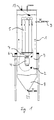
- Fig. 1 shows a sewage treatment plant according to the invention.
- a water inlet 2 for the supply of water to be treated and a water drain 3 as Clear run attached.
- a fumigation element 4 and arranged several processing elements 5, the a distributor 7 are connected to each other.
- a sedimentation area of the gassing element 4 for depositing excess Biomass.
- the area above the sedimentation area 8 is referred to as processing area 9.
- the gassing element 4 is connected to a gas supply line 6 connected via the fumigation element 4 to oxygenate the water to be treated required oxygen or atmospheric air supplied become.
- the Oxygen in the water to be treated largely consumed by the microorganisms.
- the one to be processed Water therefore flows under anoarobic conditions along the outside of the processing elements 5 back to the anaerobic sedimentation area 8.
- the water additionally by anaerobic microorganisms cleaned, for example denitrified. Farther the unwanted is suppressed here Formation of thread bacteria.
- the biomass increases of the microorganisms, so that now in the sedimentation area 8 the excess biomass is deposited becomes. From there it can be fed via a biomass outlet 24 can be removed as sewage sludge.
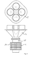
- Fig. 2 shows a sewage treatment plant according to the invention with a total four processing elements. Building this sewage treatment plant according to the invention is essentially same with the sewage treatment plant shown in Fig. 1. Especially it can clearly be seen that the four processing elements 5 via a funnel-shaped distributor are connected to the gassing element 4.
- the fumigation element consists of five disc-shaped components, the total at their peripheral edge four offset from each other at an angle of 90 °, Recesses oriented in the flow direction of the water own, about which the individual components of the Gas supply line 6 oxygen supplied under pressure becomes.
- the four processing elements 5 are disc-shaped Components built that an outer ring channel 15 and an inner ring channel 16 as well as radially have webs 17 extending between these channels. These webs 17 serve to swirl the water to be treated.
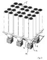
- FIG. 3 shows an arrangement of gassing elements 4, Distributors 7 and processing elements 5 with a total six gassing elements 4 and 24 treatment elements 5. Such a system is also for Suitable for cleaning up large amounts of water.
- Fig. 4 shows in turn a total of four disc-shaped elements 14 fumigation element 4, with its outlet 25 to one Distributor 7 is flanged.
- the distributor ends in a total of four processing elements 7.
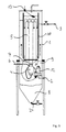
- Fig. 5 shows a sewage treatment plant according to the invention, which is similar is constructed like the sewage treatment plant shown in Fig. 1.
- the same reference numerals designate the same Parts of the sewage treatment plant.
- this sewage treatment plant is the inflow to the clear run 3 of the processing elements 5 separated over a wall 10, so that immediately before the clear run 3 between the housing 1 and the wall 10 results in an additional quiet zone.
- slats directed upwards, for example at 30 ° to wall 10 attached be so that residual suspended matter on these lamellae, that are still in the treated water be deposited. This immediately results an additional residual sedimentation area before clearing 3.
- the inlet of the gassing element 4 is with connected to the pressure side of a suction pump 12, the Suction side in the intermediate area between the sedimentation area 8 and the processing area 9 lies.
- the underwater pump 12 Through the underwater pump 12, the flow rate of the water to be treated through the gassing element 4 and the processing elements 5 additionally can be controlled, which also increases the degree of oxygenation the water in the fumigation element 4 can be influenced.
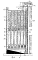
- Fig. 6 shows another example of an inventive Wastewater treatment plant, with the externally accessible Controls arranged above the housing 1 and are accessible via a ladder 30.
- the housing 1 encloses a large number of processing elements 5, the form-fitting at their respective lower end are connected to fumigation elements 4.
- fumigation elements 4 and processing element 5 arranged one above the other and connected to each other in such a way that what is to be purified Water from the respective lower treatment element 5 through one fumigation element 4 into the next Processing element 5 flows.
- the fumigation elements are connected to a compressed air supply 6.
- the lowest fumigation element 4 has another connection, that with the waste water supply line 2 is connected. Through this line 2, the wastewater is immediately in the lowest fumigation element 4 initiated where it started with Oxygen is enriched.
- the supply of waste water is regulated via a float switch 13.
- the pump 28 can, for example over a extending through the housing 1 Chain 36 operated from above the housing 1 become.
- a connecting line 37 Between the sewage sludge line 35 and the waste water supply line 2 is a connecting line 37, via which the wastewater continuously or from time to time with sewage sludge and thus with living Microorganisms can be inoculated.
- the system shown in FIG. 6 is particularly suitable for highly polluted waste water in a small space and with as little energy as possible clean. Due to the stacking of the units from fumigation elements 4 and treatment elements 5 a very long cleaning distance is achieved.
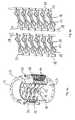
- FIG. 7 shows an arrangement of processing elements according to the invention 5 and fumigation elements 4.
- the Fumigation elements 4 consist of a sequence of disc-shaped components 14.
- the lowest fumigation element 4 consists of six components 14, while the other fumigation elements from the column there are four components each.
- Four each Components of the gassing elements 4 are with a Gas supply line 6 connected.
- In the bottom Fumigation element 4 is a component with a supply line for waste water and another component 14 connected to a sewage sludge supply line. This lowest fumigation element 4 has on his Input a flange 27 with a second Compressed gas supply line is connected.
- Via line 31 is one of the components 14 of the lowest fumigation element 4 waste water in the Interior of the fumigation element initiated.
- About the Line 22 is a further component 14 of the lowest fumigation element 4 sewage sludge the waste water added to this with living microorganisms inoculate for biological cleaning.
- the remaining four components 14 of the gassing element 4 serve to oxygenate the wastewater Supply of atmospheric compressed air or pure oxygen via the gas supply line 6.
- This gas supply line 6 is also with the Components 14 of the further gassing elements 4 connected and ensures a periodic along the column Wastewater aeration.
- the arrangement shown in FIG. 7 can have a sedimentation area and be provided with a housing and then provides a device according to the invention which is characterized by a high cleaning performance the smallest room.
- FIG. 8a shows a component 14 with an outer ring channel 15 and an inner ring channel 16 and between them Channels radially extending webs 17. Furthermore has the component 14 in this example as a whole six axial recesses 18, over which several stacked components 14 together connected or over the one above the other stacked components 14 substances exchanged can be.
- each component 14 are supplied or a gas in the outer ring channels connected to the axial recesses 18 15 and from there in with the outer ring channels connected webs 17 are passed.
- the Webs 17 made of porous, for example ceramic material, this way large quantities can be obtained Gases in a very fine distribution in an inside of the component 14 flowing liquid pressed become.
- Fig. 8a Components shown to build the fumigation element 4 from Fig. 1 can be used.
- the gas supply line 6 is then attached to one of the ends axial recesses 18 of a component stack connected, while the remaining exposed openings the axial recesses 18 are closed.
- oxygen is 6 via the gas supply line or atmospheric air in the axial recesses initiated, this air is distributed over the outer ring channels 15 in the webs 17 and by the porous, ceramic wall of the webs 17 in the water to be treated is pressed.
- FIG. 8b shows a component similar to that in FIG. 8a, the inner ring channel 16 having a passage 19 has that can accommodate a medium wave.
- FIG. 9a shows the structure of a gassing element the components shown in Fig. 8b 14.
- Die Components 14 are stacked and between the individual axial recesses 18 via screw connections 26 screwed together.
- the axial Recesses 18 of the individual components 14 are interconnected while their exposed Ends are closed.
- the gassing element 4 is at both ends each provided a flange 27 so that it is on his Inlet, for example with a submersible pump 12 and at its outlet with a distributor 7 or directly be connected to a processing element 5 can.
- FIG. 9b shows two of the many possibilities for gas routing within the fumigation element 4.
- the components 14 between the individual axial recesses 18 and between the axial recesses and the outer ring channel 15 with breakable Provide seals that are used to generate a specific Flow direction destroyed in a simple way can be.
- the gas is from one axial recess 18 via the webs 17 and Outer ring channels 15 of the opposite recess 18 fed.
- There the gas is within the axial Recess 18 directed to the next component 14, where again there is a change of sides.
- the gas is through an axial recess 18 all components 14 of the gassing element 4 fed and parallel to the opposite axial recesses 18 passed.
- Such an arrangement of components 14 can also selected for the construction of the processing elements 5 be the channel system of the components 14 for example for the supply of enzymes or nutrient solutions used for the liquid to be processed can be.
- a comparison of the bacterial agglomerates shows that the agglomerates in the sewage treatment plant according to the invention are smaller than in a bubble column reactor or in conventional sewage treatment plants, so that there is a larger interface between the microorganisms and the water to be treated, based on the amount of microorganisms, than in conventional sewage treatment technology.
- the 10 shows a further component according to the invention 14, the inner ring 16 with a bushing 19 is provided for a medium wave.
- the webs are run very thin and serve essentially the holder of the inner ring 16.
- Such components 14 can, for example, for storing a Medium wave at the respective ends of the processing elements 5 can be used.
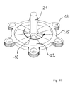
- Fig. 11 shows a rotor element having a central shaft 21 as well as freely rotating on the center shaft 21 Has webs 22 as rotor blades.
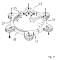
- Fig. 12 shows an injection element as it is used can, for example, to pulse large quantities of gases blow into the fumigation element 4.
- the gas is in turn via axial recesses 18 in passed the outer ring channel 15 and from there via openings 23 into the one flowing inside the injection element Blown in liquid.
- All are shown three different shapes for openings 23, namely slots, round openings and nozzle-shaped radially from the outer ring channel 15 into the inner volume protruding openings.
- Such components can in particular to enter large amounts of gas for an increase the buoyancy of the liquid or for a thorough cleaning of the fumigation elements 4 and Processing elements 5 are used.
- the outer ring channel be interrupted by seals 20 can, so that also several gases and liquids in Packing direction of the components independently of each other are guided over the axial recesses 18 can.
- the different currents are through Arrows shown.
- This component can be used with anyone of the components described are connected.
Landscapes
- Chemical & Material Sciences (AREA)
- Chemical Kinetics & Catalysis (AREA)
- Life Sciences & Earth Sciences (AREA)
- Engineering & Computer Science (AREA)
- Water Supply & Treatment (AREA)
- Biodiversity & Conservation Biology (AREA)
- Microbiology (AREA)
- Hydrology & Water Resources (AREA)
- Organic Chemistry (AREA)
- Environmental & Geological Engineering (AREA)
- Toxicology (AREA)
- Health & Medical Sciences (AREA)
- Aeration Devices For Treatment Of Activated Polluted Sludge (AREA)
- Biological Treatment Of Waste Water (AREA)
- Purification Treatments By Anaerobic Or Anaerobic And Aerobic Bacteria Or Animals (AREA)
- Separation Of Suspended Particles By Flocculating Agents (AREA)
- Water Treatment By Sorption (AREA)
Claims (15)
- Station d'épuration pour le traitement de l'eau comportant un récipient (1), qui possède une amenée (2) pour l'eau et une sortie (3) pour l'eau et dont l'espace intérieur comprend une zone de traitement (9) et une zone de sédimentation (8) située au-dessous de la précédente, au moins un élément (4) d'application d'un gaz servant à oxygéner l'eau et au moins un élément de traitement (5) étant disposés dans la zone de traitement, caractérisée en ce que le au moins un élément (4) d'application d'un gaz et le au moins un élément de traitement (5) sont disposés en superposition sous la forme d'une colonne, en ce qu'une partie de la zone de traitement est située entre ces éléments et la paroi du récipient, en ce que l'élément (4) d'application d'un gaz comporte au moins une entrée pour l'eau et au moins une sortie pour l'eau et comporte plusieurs composants en forme de disques (14), qui sont reliés entre eux pour former une pile, et à travers lesquels l'eau circule, l'entrée pour l'eau d'au moins un élément (4) d'application d'un gaz étant reliée à la zone de sédimentation (8) et en ce que le au moins un élément de traitement (5) est pourvu d'une entrée et d'une sortie et en ce que la sortie pour l'eau de l'élément (4) d'application d'un gaz est reliée selon une liaison par formes complémentaires à l'entrée d'au moins un élément de traitement, l'eau sortant de l'élément (4) d'application d'un gaz étant amenée à tourbillonner et étant mélangée d'une manière ciblée lorsqu'elle traverse l'élément de traitement (5) et circulant, une fois sortie de l'élément de traitement, entre la face extérieure de l'élément de traitement et la paroi du récipient en direction de la zone de sédimentation.
- Station d'épuration selon la revendication 1, caractérisée en ce que la sortie du ou d'un élément de traitement (5) est reliée à l'entrée d'un autre élément (4) d'application d'un gaz, auquel est raccordé un autre élément de traitement (5).
- Station d'épuration selon au moins l'une des revendications précédentes, caractérisée en ce que plusieurs éléments d'application d'un gaz et plusieurs éléments de traitement sont disposés alternativement d'une manière superposée pour former une colonne.
- Station d'épuration selon au moins l'une des revendications précédentes, caractérisée en ce que chaque élément (4) d'application d'un gaz est relié, par l'intermédiaire d'un distributeur (7), à plusieurs éléments de traitement (5).
- Station d'épuration selon au moins l'une des revendications précédentes, caractérisée en ce que l'évacuation pour l'eau est séparée de la zone de traitement (9), par une paroi (10), la partie séparée située à proximité de la zone de sédimentation (8) communiquant avec la zone de traitement et/ou de sédimentation (8).
- Station d'épuration selon la revendication 5, caractérisée en ce que dans la partie séparée, le récipient (1) ou la paroi (10) sont pourvus de lamelles qui s'étendent vers le haut.
- Station d'épuration selon au moins l'une des revendications précédentes, caractérisée en ce que l'entrée de l'élément (4) d'application d'un gaz est reliée au côté refoulement d'une pompe immergée (12) disposée dans le récipient (1) et dont la tubulure d'aspiration est située entre la zone de sédimentation et la zone de traitement (9).
- Station d'épuration selon au moins l'une des revendications précédentes, caractérisée en ce que l'élément (4) d'application d'un gaz et/ou l'élément de traitement (5) sont constitués au moins en partie par une pile de composants (14) en forme de disques, qui sont reliés entre eux selon une liaison par formes complémentaires et sont identiques entre eux ou au moins similaires.
- Station d'épuration selon la revendication 8, caractérisée en ce que les composants (14) possèdent chacun respectivement au moins un connecteur (15) et un canal annulaire intérieur (16) et plusieurs barrettes, qui s'étendent radialement entre le canal annulaire extérieur (15) et le canal annulaire intérieur (16).
- Station d'épuration selon la revendication 9, caractérisée en ce que les barrettes (17) débouchent dans le canal annulaire extérieur (15) et/ou dans le canal annulaire intérieur (16).
- Station d'épuration selon les revendications 9 et 10, caractérisée en ce que les composants (14) possèdent au moins un évidement axial (18) à l'extérieur du canal annulaire extérieur (15).
- Station d'épuration selon au moins l'une des revendications 9 à 11, caractérisée en ce que les canaux, les évidements axiaux (18) et les barrettes (17) sont séparés les uns des autres par l'intermédiaire de parois de séparation pouvant être retirées ou des barreaux de séparation pouvant être retirés ou pouvant être rompus et sont reliés entre eux par retrait ou rupture des parois de séparation (20) de sorte que seul un nombre prédéterminé des canaux, évidements (18) et barrettes (17) communiquent entre eux.
- Station d'épuration selon au moins l'une des revendications 9 à 12, caractérisée en ce que les barrettes (17) possèdent une structure poreuse perméable à l'air.
- Station d'épuration selon au moins l'une des revendications 9 à 12, caractérisée en ce que les composants (14) possèdent, au moins en partie au centre du canal annulaire antérieur (16), un passage (19) servant à loger un arbre médian (21) qui s'étend le long de la pile.
- Station d'épuration selon la revendication 14, caractérisée en ce que des éléments agitateurs, des éléments de vis ou des pales de rotor (22), qui servent à produire un écoulement et qui s'étendent à partir de l'arbre médian (21) dans l'espace intercalaire présent entre le canal annulaire intérieur (16) et le canal annulaire extérieur (15), sont disposés sur l'arbre médian (21), dans une partie des composants (14).
Applications Claiming Priority (3)
| Application Number | Priority Date | Filing Date | Title |
|---|---|---|---|
| DE19621156A DE19621156A1 (de) | 1996-05-14 | 1996-05-14 | Klärwerk zur Aufbereitung von Wasser |
| DE19621156 | 1996-05-14 | ||
| PCT/DE1997/001010 WO1997043220A1 (fr) | 1996-05-14 | 1997-05-13 | Station d'epuration pour traitement des eaux |
Publications (2)
| Publication Number | Publication Date |
|---|---|
| EP0902761A1 EP0902761A1 (fr) | 1999-03-24 |
| EP0902761B1 true EP0902761B1 (fr) | 2001-08-29 |
Family
ID=7795341
Family Applications (1)
| Application Number | Title | Priority Date | Filing Date |
|---|---|---|---|
| EP19970926962 Expired - Lifetime EP0902761B1 (fr) | 1996-05-14 | 1997-05-13 | Station d'epuration pour traitement des eaux |
Country Status (8)
| Country | Link |
|---|---|
| US (1) | US6132602A (fr) |
| EP (1) | EP0902761B1 (fr) |
| AT (1) | ATE204833T1 (fr) |
| CA (1) | CA2253456A1 (fr) |
| DE (2) | DE19621156A1 (fr) |
| ES (1) | ES2163169T3 (fr) |
| PT (1) | PT902761E (fr) |
| WO (1) | WO1997043220A1 (fr) |
Families Citing this family (6)
| Publication number | Priority date | Publication date | Assignee | Title |
|---|---|---|---|---|
| DE19860942C1 (de) * | 1998-12-29 | 2000-05-04 | Wolfgang Luehr | Vorrichtung zur aeroben mikrobiologischen Aufbereitung von Abwasser |
| US6752926B2 (en) | 2000-10-20 | 2004-06-22 | Trustees Of Stevens Institute Of Technology | Method and apparatus for treatment of wastewater |
| GB0724813D0 (en) * | 2007-12-20 | 2008-01-30 | Questor Technologies Ltd | Improvements relating to water treatment |
| CA2713952C (fr) | 2008-01-28 | 2018-01-16 | Ntnu Technology Transfer As | Procede et dispositif pour le traitement d'eaux usees |
| DE102009043134B4 (de) * | 2009-09-18 | 2014-05-22 | Bgd Boden- Und Grundwasserlabor Gmbh | Verfahren zur Ermittlung von Stoffaustauschraten zwischen Wasserkörper und porösen Medien in Oberflächengewässern |
| CN114344993A (zh) * | 2021-12-22 | 2022-04-15 | 席芳芳 | 一种废油回收利用装置 |
Family Cites Families (11)
| Publication number | Priority date | Publication date | Assignee | Title |
|---|---|---|---|---|
| JPS5551595Y2 (fr) * | 1972-07-31 | 1980-12-01 | ||
| DE2752190A1 (de) * | 1977-11-23 | 1979-05-31 | Roth Kg Metallwerk | Kleinklaervorrichtung |
| US4231863A (en) * | 1979-04-26 | 1980-11-04 | Sutphin Eldon M | Method and apparatus for treating water |
| CH655083A5 (en) * | 1981-06-29 | 1986-03-27 | Sulzer Ag | Reaction vessel for biological waste-water purification plants |
| US4892818A (en) * | 1987-02-05 | 1990-01-09 | Floyd Ramp | Bioreactor |
| DE3916250B4 (de) * | 1988-07-14 | 2005-02-17 | Lühr, Wolfgang | Mischkammerelement, Mischkammereinheit mit derartigen Mischkammerelementen, Verwendungen der Mischkammereinheit |
| US4976863A (en) * | 1989-01-26 | 1990-12-11 | Pec Research, Inc. | Wastewater treatment process |
| DE8906830U1 (fr) * | 1989-05-20 | 1990-09-13 | Zimmer, Geb. Goldenbaum, Gertraud, 6700 Ludwigshafen, De | |
| DE4100983A1 (de) * | 1991-01-15 | 1992-07-16 | Borsig Babcock Ag | Vorrichtung zur biologischen reinigung von abwasser |
| US5156742A (en) * | 1992-02-25 | 1992-10-20 | Smith & Loveless, Inc. | Liquid treatment method and apparatus |
| DE29502701U1 (de) * | 1995-02-18 | 1995-04-06 | Redwanz Dieter | Belüftungsvorrichtung für Abwässer |
-
1996
- 1996-05-14 DE DE19621156A patent/DE19621156A1/de active Pending
-
1997
- 1997-05-13 CA CA 2253456 patent/CA2253456A1/fr not_active Abandoned
- 1997-05-13 DE DE59704461T patent/DE59704461D1/de not_active Expired - Fee Related
- 1997-05-13 AT AT97926962T patent/ATE204833T1/de not_active IP Right Cessation
- 1997-05-13 WO PCT/DE1997/001010 patent/WO1997043220A1/fr active IP Right Grant
- 1997-05-13 US US09/180,474 patent/US6132602A/en not_active Expired - Fee Related
- 1997-05-13 ES ES97926962T patent/ES2163169T3/es not_active Expired - Lifetime
- 1997-05-13 EP EP19970926962 patent/EP0902761B1/fr not_active Expired - Lifetime
- 1997-05-13 PT PT97926962T patent/PT902761E/pt unknown
Also Published As
| Publication number | Publication date |
|---|---|
| WO1997043220A1 (fr) | 1997-11-20 |
| EP0902761A1 (fr) | 1999-03-24 |
| ATE204833T1 (de) | 2001-09-15 |
| ES2163169T3 (es) | 2002-01-16 |
| CA2253456A1 (fr) | 1997-11-20 |
| DE19621156A1 (de) | 1997-11-20 |
| US6132602A (en) | 2000-10-17 |
| PT902761E (pt) | 2002-02-28 |
| DE59704461D1 (de) | 2001-10-04 |
Similar Documents
| Publication | Publication Date | Title |
|---|---|---|
| DE3738295A1 (de) | Reaktor und verfahren zum biologischen reinigen von schadstoffhaltigem wasser | |
| EP2468686A1 (fr) | Installation de préparation d'eaux usées intégrée | |
| EP0249861B1 (fr) | Procédé pour la purification biologique d'air d'échappement et d'eau usée | |
| EP0306054B1 (fr) | Dispositif pour l'épuration aérobie biologique d'eau contenant de la matière toxique | |
| DE3427448A1 (de) | Verfahren und vorrichtung zur biologischen abwasserreinigung | |
| DE2404289B2 (de) | Belebungsbecken zur biologischen reinigung von abwasser | |
| EP0902761B1 (fr) | Station d'epuration pour traitement des eaux | |
| DE3916520A1 (de) | Biologischer klaerreaktor nach dem aeroben/fakultativen prinzip | |
| DE3503723C2 (fr) | ||
| CH623294A5 (fr) | ||
| EP0201924A2 (fr) | Procédé et dispositif pour la purification d'eau usée | |
| DE2909724C2 (de) | Anlage für die biologische Abwasserreinigung | |
| EP1307409A1 (fr) | Procede aux boues activees et dispositif de traitement des eaux usees avec elimination du phosphore et de l'azote | |
| EP2289855B1 (fr) | Installation de nettoyage d'eaux usées et procédé de nettoyage d'eaux usées | |
| DE2310978C3 (de) | Belüftungsbecken für eine biologische Kläranlage | |
| DE1609016A1 (de) | Verfahren und Vorrichtung zur biologischen Reinigung von Fluessigkeiten durch Belueftung | |
| DE2060995A1 (de) | Verfahren und Vorrichtung fuer kontinuierliches Behandeln von Fluessigkeiten | |
| DE19631796A1 (de) | Verfahren und Vorrichtung zur Reinigung von Abwassern | |
| EP0749942A2 (fr) | Appareil de traitement biologique des eaux résiduaires | |
| DE3520652A1 (de) | Klaerbecken zur aeroben oder fakultativen reinigung organischer abwaesser | |
| DE10301858A1 (de) | Kleinkläranlage | |
| EP0812807A2 (fr) | Procédé et réacteur pour le traitement microbiologique continue des eaux usées fortement polluées | |
| EP0369455B1 (fr) | Procédé et installation pour le traitement biologique des eaux usées | |
| DE2420744B2 (de) | Vorrichtung zum Reinigen von Abwasser | |
| EP0739860A1 (fr) | Procédé et dispositif pour le traitement biologique de l'eau usée |
Legal Events
| Date | Code | Title | Description |
|---|---|---|---|
| PUAI | Public reference made under article 153(3) epc to a published international application that has entered the european phase |
Free format text: ORIGINAL CODE: 0009012 |
|
| 17P | Request for examination filed |
Effective date: 19981104 |
|
| AK | Designated contracting states |
Kind code of ref document: A1 Designated state(s): AT BE CH DE DK ES FI FR GB GR IE IT LI LU MC NL PT SE |
|
| GRAG | Despatch of communication of intention to grant |
Free format text: ORIGINAL CODE: EPIDOS AGRA |
|
| GRAG | Despatch of communication of intention to grant |
Free format text: ORIGINAL CODE: EPIDOS AGRA |
|
| 17Q | First examination report despatched |
Effective date: 20001030 |
|
| GRAG | Despatch of communication of intention to grant |
Free format text: ORIGINAL CODE: EPIDOS AGRA |
|
| GRAH | Despatch of communication of intention to grant a patent |
Free format text: ORIGINAL CODE: EPIDOS IGRA |
|
| GRAH | Despatch of communication of intention to grant a patent |
Free format text: ORIGINAL CODE: EPIDOS IGRA |
|
| GRAA | (expected) grant |
Free format text: ORIGINAL CODE: 0009210 |
|
| AK | Designated contracting states |
Kind code of ref document: B1 Designated state(s): AT BE CH DE DK ES FI FR GB GR IE IT LI LU MC NL PT SE |
|
| PG25 | Lapsed in a contracting state [announced via postgrant information from national office to epo] |
Ref country code: NL Free format text: LAPSE BECAUSE OF FAILURE TO SUBMIT A TRANSLATION OF THE DESCRIPTION OR TO PAY THE FEE WITHIN THE PRESCRIBED TIME-LIMIT Effective date: 20010829 Ref country code: IE Free format text: LAPSE BECAUSE OF FAILURE TO SUBMIT A TRANSLATION OF THE DESCRIPTION OR TO PAY THE FEE WITHIN THE PRESCRIBED TIME-LIMIT Effective date: 20010829 Ref country code: FI Free format text: LAPSE BECAUSE OF FAILURE TO SUBMIT A TRANSLATION OF THE DESCRIPTION OR TO PAY THE FEE WITHIN THE PRESCRIBED TIME-LIMIT Effective date: 20010829 |
|
| REF | Corresponds to: |
Ref document number: 204833 Country of ref document: AT Date of ref document: 20010915 Kind code of ref document: T |
|
| REG | Reference to a national code |
Ref country code: CH Ref legal event code: EP |
|
| REG | Reference to a national code |
Ref country code: IE Ref legal event code: FG4D Free format text: GERMAN |
|
| REF | Corresponds to: |
Ref document number: 59704461 Country of ref document: DE Date of ref document: 20011004 |
|
| PG25 | Lapsed in a contracting state [announced via postgrant information from national office to epo] |
Ref country code: SE Free format text: LAPSE BECAUSE OF FAILURE TO SUBMIT A TRANSLATION OF THE DESCRIPTION OR TO PAY THE FEE WITHIN THE PRESCRIBED TIME-LIMIT Effective date: 20011129 Ref country code: DK Free format text: LAPSE BECAUSE OF FAILURE TO SUBMIT A TRANSLATION OF THE DESCRIPTION OR TO PAY THE FEE WITHIN THE PRESCRIBED TIME-LIMIT Effective date: 20011129 |
|
| REG | Reference to a national code |
Ref country code: CH Ref legal event code: NV Representative=s name: TROESCH SCHEIDEGGER WERNER AG |
|
| ET | Fr: translation filed | ||
| GBT | Gb: translation of ep patent filed (gb section 77(6)(a)/1977) |
Effective date: 20011117 |
|
| REG | Reference to a national code |
Ref country code: GB Ref legal event code: IF02 |
|
| REG | Reference to a national code |
Ref country code: ES Ref legal event code: FG2A Ref document number: 2163169 Country of ref document: ES Kind code of ref document: T3 |
|
| NLV1 | Nl: lapsed or annulled due to failure to fulfill the requirements of art. 29p and 29m of the patents act | ||
| REG | Reference to a national code |
Ref country code: PT Ref legal event code: SC4A Free format text: AVAILABILITY OF NATIONAL TRANSLATION Effective date: 20011127 Ref country code: GR Ref legal event code: EP Ref document number: 20010401970 Country of ref document: GR |
|
| PG25 | Lapsed in a contracting state [announced via postgrant information from national office to epo] |
Ref country code: MC Free format text: LAPSE BECAUSE OF NON-PAYMENT OF DUE FEES Effective date: 20020513 Ref country code: LU Free format text: LAPSE BECAUSE OF NON-PAYMENT OF DUE FEES Effective date: 20020513 |
|
| REG | Reference to a national code |
Ref country code: IE Ref legal event code: FD4D |
|
| PG25 | Lapsed in a contracting state [announced via postgrant information from national office to epo] |
Ref country code: BE Free format text: LAPSE BECAUSE OF NON-PAYMENT OF DUE FEES Effective date: 20020531 |
|
| PLBE | No opposition filed within time limit |
Free format text: ORIGINAL CODE: 0009261 |
|
| STAA | Information on the status of an ep patent application or granted ep patent |
Free format text: STATUS: NO OPPOSITION FILED WITHIN TIME LIMIT |
|
| 26N | No opposition filed | ||
| PGFP | Annual fee paid to national office [announced via postgrant information from national office to epo] |
Ref country code: GR Payment date: 20031128 Year of fee payment: 7 |
|
| PGFP | Annual fee paid to national office [announced via postgrant information from national office to epo] |
Ref country code: AT Payment date: 20031130 Year of fee payment: 7 |
|
| PG25 | Lapsed in a contracting state [announced via postgrant information from national office to epo] |
Ref country code: AT Free format text: LAPSE BECAUSE OF NON-PAYMENT OF DUE FEES Effective date: 20040513 |
|
| PG25 | Lapsed in a contracting state [announced via postgrant information from national office to epo] |
Ref country code: GR Free format text: LAPSE BECAUSE OF NON-PAYMENT OF DUE FEES Effective date: 20041203 |
|
| REG | Reference to a national code |
Ref country code: CH Ref legal event code: PL |
|
| REG | Reference to a national code |
Ref country code: CH Ref legal event code: AEN Free format text: DAS PATENT IST AUFGRUND DES WEITERBEHANDLUNGSANTRAGS VOM 07.02.2005 REAKTIVIERT WORDEN. |
|
| PGFP | Annual fee paid to national office [announced via postgrant information from national office to epo] |
Ref country code: PT Payment date: 20050504 Year of fee payment: 9 |
|
| PGFP | Annual fee paid to national office [announced via postgrant information from national office to epo] |
Ref country code: GB Payment date: 20050516 Year of fee payment: 9 |
|
| PGFP | Annual fee paid to national office [announced via postgrant information from national office to epo] |
Ref country code: FR Payment date: 20050530 Year of fee payment: 9 |
|
| PGFP | Annual fee paid to national office [announced via postgrant information from national office to epo] |
Ref country code: ES Payment date: 20050531 Year of fee payment: 9 |
|
| PGFP | Annual fee paid to national office [announced via postgrant information from national office to epo] |
Ref country code: CH Payment date: 20050729 Year of fee payment: 9 |
|
| PG25 | Lapsed in a contracting state [announced via postgrant information from national office to epo] |
Ref country code: GB Free format text: LAPSE BECAUSE OF NON-PAYMENT OF DUE FEES Effective date: 20060513 |
|
| PG25 | Lapsed in a contracting state [announced via postgrant information from national office to epo] |
Ref country code: ES Free format text: LAPSE BECAUSE OF NON-PAYMENT OF DUE FEES Effective date: 20060516 |
|
| PG25 | Lapsed in a contracting state [announced via postgrant information from national office to epo] |
Ref country code: LI Free format text: LAPSE BECAUSE OF NON-PAYMENT OF DUE FEES Effective date: 20060531 Ref country code: CH Free format text: LAPSE BECAUSE OF NON-PAYMENT OF DUE FEES Effective date: 20060531 |
|
| PGFP | Annual fee paid to national office [announced via postgrant information from national office to epo] |
Ref country code: IT Payment date: 20060531 Year of fee payment: 10 |
|
| PG25 | Lapsed in a contracting state [announced via postgrant information from national office to epo] |
Ref country code: PT Free format text: LAPSE BECAUSE OF NON-PAYMENT OF DUE FEES Effective date: 20061113 |
|
| REG | Reference to a national code |
Ref country code: PT Ref legal event code: MM4A Free format text: LAPSE DUE TO NON-PAYMENT OF FEES Effective date: 20061113 |
|
| REG | Reference to a national code |
Ref country code: CH Ref legal event code: PL |
|
| GBPC | Gb: european patent ceased through non-payment of renewal fee |
Effective date: 20060513 |
|
| PG25 | Lapsed in a contracting state [announced via postgrant information from national office to epo] |
Ref country code: DE Free format text: LAPSE BECAUSE OF NON-PAYMENT OF DUE FEES Effective date: 20070201 |
|
| REG | Reference to a national code |
Ref country code: FR Ref legal event code: ST Effective date: 20070131 |
|
| REG | Reference to a national code |
Ref country code: ES Ref legal event code: FD2A Effective date: 20060516 |
|
| PG25 | Lapsed in a contracting state [announced via postgrant information from national office to epo] |
Ref country code: FR Free format text: LAPSE BECAUSE OF NON-PAYMENT OF DUE FEES Effective date: 20060531 |
|
| PG25 | Lapsed in a contracting state [announced via postgrant information from national office to epo] |
Ref country code: IT Free format text: LAPSE BECAUSE OF NON-PAYMENT OF DUE FEES Effective date: 20070513 |
|
| PGFP | Annual fee paid to national office [announced via postgrant information from national office to epo] |
Ref country code: DE Payment date: 20060531 Year of fee payment: 10 |