EP0249861A2 - Procédé pour la purification biologique d'air d'échappement et d'eau usée - Google Patents
Procédé pour la purification biologique d'air d'échappement et d'eau usée Download PDFInfo
- Publication number
- EP0249861A2 EP0249861A2 EP87108345A EP87108345A EP0249861A2 EP 0249861 A2 EP0249861 A2 EP 0249861A2 EP 87108345 A EP87108345 A EP 87108345A EP 87108345 A EP87108345 A EP 87108345A EP 0249861 A2 EP0249861 A2 EP 0249861A2
- Authority
- EP
- European Patent Office
- Prior art keywords
- gas
- liquid
- waste water
- column
- wastewater
- Prior art date
- Legal status (The legal status is an assumption and is not a legal conclusion. Google has not performed a legal analysis and makes no representation as to the accuracy of the status listed.)
- Granted
Links
- 239000002351 wastewater Substances 0.000 title claims abstract description 31
- 238000000034 method Methods 0.000 title claims abstract description 15
- 238000000746 purification Methods 0.000 title claims abstract description 10
- 239000007789 gas Substances 0.000 claims abstract description 53
- 239000007788 liquid Substances 0.000 claims abstract description 53
- 239000002028 Biomass Substances 0.000 claims abstract description 14
- QVGXLLKOCUKJST-UHFFFAOYSA-N atomic oxygen Chemical compound [O] QVGXLLKOCUKJST-UHFFFAOYSA-N 0.000 claims abstract description 12
- 229910052760 oxygen Inorganic materials 0.000 claims abstract description 12
- 239000001301 oxygen Substances 0.000 claims abstract description 12
- 239000003570 air Substances 0.000 claims abstract description 10
- 239000007900 aqueous suspension Substances 0.000 claims abstract 2
- 239000007921 spray Substances 0.000 claims description 12
- 239000003344 environmental pollutant Substances 0.000 claims description 11
- 231100000719 pollutant Toxicity 0.000 claims description 11
- 239000002689 soil Substances 0.000 claims description 10
- 239000010802 sludge Substances 0.000 claims description 8
- 238000011010 flushing procedure Methods 0.000 claims description 6
- 239000000126 substance Substances 0.000 claims description 6
- 238000004065 wastewater treatment Methods 0.000 claims description 6
- 239000010796 biological waste Substances 0.000 claims description 4
- 239000000725 suspension Substances 0.000 claims description 4
- 230000015556 catabolic process Effects 0.000 claims description 3
- 238000006731 degradation reaction Methods 0.000 claims description 3
- 239000002912 waste gas Substances 0.000 claims description 3
- 238000004140 cleaning Methods 0.000 claims 1
- 239000007857 degradation product Substances 0.000 claims 1
- 235000016709 nutrition Nutrition 0.000 claims 1
- 238000004064 recycling Methods 0.000 claims 1
- 238000010276 construction Methods 0.000 abstract description 2
- 238000006065 biodegradation reaction Methods 0.000 description 5
- YXFVVABEGXRONW-UHFFFAOYSA-N Toluene Chemical compound CC1=CC=CC=C1 YXFVVABEGXRONW-UHFFFAOYSA-N 0.000 description 3
- 238000013461 design Methods 0.000 description 3
- 238000004821 distillation Methods 0.000 description 3
- 238000005265 energy consumption Methods 0.000 description 3
- 244000005700 microbiome Species 0.000 description 3
- 235000015097 nutrients Nutrition 0.000 description 3
- OKTJSMMVPCPJKN-UHFFFAOYSA-N Carbon Chemical compound [C] OKTJSMMVPCPJKN-UHFFFAOYSA-N 0.000 description 2
- 238000010521 absorption reaction Methods 0.000 description 2
- 238000010586 diagram Methods 0.000 description 2
- 238000004519 manufacturing process Methods 0.000 description 2
- 238000004062 sedimentation Methods 0.000 description 2
- 238000000926 separation method Methods 0.000 description 2
- 239000010865 sewage Substances 0.000 description 2
- 239000007787 solid Substances 0.000 description 2
- 238000012546 transfer Methods 0.000 description 2
- XLYOFNOQVPJJNP-UHFFFAOYSA-N water Substances O XLYOFNOQVPJJNP-UHFFFAOYSA-N 0.000 description 2
- UGFAIRIUMAVXCW-UHFFFAOYSA-N Carbon monoxide Chemical compound [O+]#[C-] UGFAIRIUMAVXCW-UHFFFAOYSA-N 0.000 description 1
- 241001503485 Mammuthus Species 0.000 description 1
- GRYLNZFGIOXLOG-UHFFFAOYSA-N Nitric acid Chemical compound O[N+]([O-])=O GRYLNZFGIOXLOG-UHFFFAOYSA-N 0.000 description 1
- NINIDFKCEFEMDL-UHFFFAOYSA-N Sulfur Chemical compound [S] NINIDFKCEFEMDL-UHFFFAOYSA-N 0.000 description 1
- QAOWNCQODCNURD-UHFFFAOYSA-N Sulfuric acid Chemical compound OS(O)(=O)=O QAOWNCQODCNURD-UHFFFAOYSA-N 0.000 description 1
- 238000005299 abrasion Methods 0.000 description 1
- 239000006096 absorbing agent Substances 0.000 description 1
- 239000002253 acid Substances 0.000 description 1
- 150000007513 acids Chemical class 0.000 description 1
- 238000004887 air purification Methods 0.000 description 1
- 230000009286 beneficial effect Effects 0.000 description 1
- 238000006243 chemical reaction Methods 0.000 description 1
- 239000003245 coal Substances 0.000 description 1
- 239000002361 compost Substances 0.000 description 1
- 239000000470 constituent Substances 0.000 description 1
- 230000007547 defect Effects 0.000 description 1
- 238000011161 development Methods 0.000 description 1
- 239000006185 dispersion Substances 0.000 description 1
- 230000000694 effects Effects 0.000 description 1
- 238000005516 engineering process Methods 0.000 description 1
- 238000005188 flotation Methods 0.000 description 1
- 239000003546 flue gas Substances 0.000 description 1
- 239000012530 fluid Substances 0.000 description 1
- 238000003958 fumigation Methods 0.000 description 1
- 150000008282 halocarbons Chemical class 0.000 description 1
- 238000009434 installation Methods 0.000 description 1
- 238000012423 maintenance Methods 0.000 description 1
- 230000014759 maintenance of location Effects 0.000 description 1
- 238000002156 mixing Methods 0.000 description 1
- 229910017604 nitric acid Inorganic materials 0.000 description 1
- 229910017464 nitrogen compound Inorganic materials 0.000 description 1
- 150000002830 nitrogen compounds Chemical class 0.000 description 1
- 239000002957 persistent organic pollutant Substances 0.000 description 1
- 230000001105 regulatory effect Effects 0.000 description 1
- 150000003839 salts Chemical class 0.000 description 1
- 239000002594 sorbent Substances 0.000 description 1
- 238000001228 spectrum Methods 0.000 description 1
- 238000005507 spraying Methods 0.000 description 1
- 229910052717 sulfur Inorganic materials 0.000 description 1
- 239000011593 sulfur Substances 0.000 description 1
- 235000011149 sulphuric acid Nutrition 0.000 description 1
- 239000002562 thickening agent Substances 0.000 description 1
- 238000005406 washing Methods 0.000 description 1
Images

Classifications
-
- C—CHEMISTRY; METALLURGY
- C02—TREATMENT OF WATER, WASTE WATER, SEWAGE, OR SLUDGE
- C02F—TREATMENT OF WATER, WASTE WATER, SEWAGE, OR SLUDGE
- C02F3/00—Biological treatment of water, waste water, or sewage
- C02F3/02—Aerobic processes
- C02F3/12—Activated sludge processes
- C02F3/26—Activated sludge processes using pure oxygen or oxygen-rich gas
-
- B—PERFORMING OPERATIONS; TRANSPORTING
- B01—PHYSICAL OR CHEMICAL PROCESSES OR APPARATUS IN GENERAL
- B01D—SEPARATION
- B01D53/00—Separation of gases or vapours; Recovering vapours of volatile solvents from gases; Chemical or biological purification of waste gases, e.g. engine exhaust gases, smoke, fumes, flue gases, aerosols
- B01D53/34—Chemical or biological purification of waste gases
- B01D53/74—General processes for purification of waste gases; Apparatus or devices specially adapted therefor
- B01D53/84—Biological processes
-
- C—CHEMISTRY; METALLURGY
- C02—TREATMENT OF WATER, WASTE WATER, SEWAGE, OR SLUDGE
- C02F—TREATMENT OF WATER, WASTE WATER, SEWAGE, OR SLUDGE
- C02F3/00—Biological treatment of water, waste water, or sewage
- C02F3/02—Aerobic processes
- C02F3/025—Biological purification using sources of oxygen other than air, oxygen or ozone
-
- C—CHEMISTRY; METALLURGY
- C02—TREATMENT OF WATER, WASTE WATER, SEWAGE, OR SLUDGE
- C02F—TREATMENT OF WATER, WASTE WATER, SEWAGE, OR SLUDGE
- C02F3/00—Biological treatment of water, waste water, or sewage
- C02F3/02—Aerobic processes
- C02F3/12—Activated sludge processes
-
- C—CHEMISTRY; METALLURGY
- C02—TREATMENT OF WATER, WASTE WATER, SEWAGE, OR SLUDGE
- C02F—TREATMENT OF WATER, WASTE WATER, SEWAGE, OR SLUDGE
- C02F3/00—Biological treatment of water, waste water, or sewage
- C02F3/02—Aerobic processes
- C02F3/12—Activated sludge processes
- C02F3/20—Activated sludge processes using diffusers
-
- Y—GENERAL TAGGING OF NEW TECHNOLOGICAL DEVELOPMENTS; GENERAL TAGGING OF CROSS-SECTIONAL TECHNOLOGIES SPANNING OVER SEVERAL SECTIONS OF THE IPC; TECHNICAL SUBJECTS COVERED BY FORMER USPC CROSS-REFERENCE ART COLLECTIONS [XRACs] AND DIGESTS
- Y02—TECHNOLOGIES OR APPLICATIONS FOR MITIGATION OR ADAPTATION AGAINST CLIMATE CHANGE
- Y02A—TECHNOLOGIES FOR ADAPTATION TO CLIMATE CHANGE
- Y02A50/00—TECHNOLOGIES FOR ADAPTATION TO CLIMATE CHANGE in human health protection, e.g. against extreme weather
- Y02A50/20—Air quality improvement or preservation, e.g. vehicle emission control or emission reduction by using catalytic converters
-
- Y—GENERAL TAGGING OF NEW TECHNOLOGICAL DEVELOPMENTS; GENERAL TAGGING OF CROSS-SECTIONAL TECHNOLOGIES SPANNING OVER SEVERAL SECTIONS OF THE IPC; TECHNICAL SUBJECTS COVERED BY FORMER USPC CROSS-REFERENCE ART COLLECTIONS [XRACs] AND DIGESTS
- Y02—TECHNOLOGIES OR APPLICATIONS FOR MITIGATION OR ADAPTATION AGAINST CLIMATE CHANGE
- Y02W—CLIMATE CHANGE MITIGATION TECHNOLOGIES RELATED TO WASTEWATER TREATMENT OR WASTE MANAGEMENT
- Y02W10/00—Technologies for wastewater treatment
- Y02W10/10—Biological treatment of water, waste water, or sewage
Definitions
- the invention relates to a method for biological waste gas or waste water purification, in which the waste gas or waste water is passed through a gas-liquid contact apparatus.
- the invention further relates to a device for carrying out the method.
- biofilters can only be operated at low gas speeds (-0.1 m / s or less) and therefore require large areas. With a high pollutant content and the associated high biomass growth, they tend to grow. If strong acids (HCl, HF, H2SO4 or HNO3) arise during biodegradation, such as during the degradation of halogenated hydrocarbons or various sulfur or nitrogen compounds, the pH value in the biofilters (e.g. compost filters) drops and the biodegradation rate comes to a standstill , if one does not carry out a pH control by adding base, which increases the pressure loss and maldistribution problems (liquid fringing in countercurrent) or effective losses (liquid carries along pollutant!).
- strong acids HCl, HF, H2SO4 or HNO3
- the known bio-washers e.g. Nozzle scrubbers, packed columns or conventional tray columns (see e.g. Japanese Pat. Application No. 51-67048) with a downstream bioreactor have the main disadvantage of the extremely large liquid flow from the scrubber to the bioreactor and back, which is usually required to transport dissolved pollutants and dissolved oxygen.
- This disadvantage can be reduced by adding sorbents (e.g. activated carbon); however, these measures entail new disadvantages (abrasion, maintenance and investment costs for coal bunkering and disposal).
- a further disadvantage in the case of the nozzle washer is the increasing complexity of the system when low solubility of the pollutants and / or low permissible final concentration make a multi-stage design necessary.
- This object is achieved in that a bottom column is used as the gas-liquid contact apparatus and the biomass required for biodegradation in the liquid is suspended and that known weirs or drain pipes ensure that a liquid hold-up per tray of more than 0.07 m3, preferably more than 0.15 m3 per m2 column cross-section occurs during operation.
- a tray column is to be understood here as a column with at least two trays on which there is an at least partially fumigated liquid, that is to say through which the gas stream to be cleaned flows, the gas through openings (slots, holes, valves) in the trays or in with internals connected to the floors (bells, chimneys, channels, etc.) emerge and thus flow through the floors and at least part of the liquid thereon in succession in countercurrent or cross / countercurrent to the gas.
- a large holdup is aimed for in the method according to the invention in order to achieve the required reaction volume with a not too large number of trays.
- a flushing of the gas space can be done the inside surfaces of the channels of adhering biomass can be carried out particularly easily if pipes with suitable spray nozzles and spray holes are ever installed under the floors perpendicular to the channels.
- These tubes are preferably rotatable about their longitudinal axis. This can improve the rinsing effect.
- the decisive difference of the method according to the invention compared to a conventional bio-washer is that most of the volume required for biodegradation can be accommodated in the bottom column (integrated absorber / bioreactor). If required, however, additional post-reactors (e.g. pump templates) can be switched on in the external liquid circuits.
- additional post-reactors e.g. pump templates
- the energy costs are far less than 1/10 of the energy costs (mainly for liquid production) of an equally effective multi-stage biological nozzle washer system if poorly water-soluble substances (e.g. toluene) have to be washed out.
- poorly water-soluble substances e.g. toluene
- wastewater streams can also advantageously be biologically cleaned with the bioreactor according to the invention.
- the wastewater to be cleaned is passed through the tray column and air, oxygen or oxygen-containing gas flows through it.
- part of the biomass is separated from the cleaned wastewater and returned to the inflowing wastewater or the column. This process is particularly suitable for highly contaminated wastewater, especially when an extremely space-saving design is important.
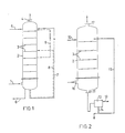
- the raw gas is fed through the feed line 1 at the lower end of the tray column 2. It then flows through the trays 3 and enters the head as a purified gas the bottom column 2 through the nozzle 4 again.
- Nutrient solution is fed through the feed line 5 at the top of the column or at other points.
- the discharge of excess sludge and used nutrient solution can take place from the sump through line 6 or from one of the trays 3. Sedimentation and return of the sludge can be provided (not shown).
- Part of the suspension is normally recirculated to the top of the column (circuit 7) or to one of the trays (circuit 8).
- a return 9 can also be provided within the floors.
- the dashed circuits 8 and 9 form a two-stage return.
- Devices for regulating the pH value can be built into the circuits in order to keep the pH value constant.
- the circuits can also be used to even out the biomass concentration and to supply the microorganisms with inorganic nutrient salts, which can be dissolved or in solid form, for example fed into the circuits.
- the concentration of organic substances dissolved in the suspension (food for the microorganisms) and the oxygen can be equalized by external circuits.
- the tray column 2 is used for wastewater treatment.
- the raw waste water is fed to the top floor 3 via the inlet 10 and flows from there successively over the floors 3 to the liquid outlet 11 and from there into the sludge retention device 12. From here, the treated waste water runs through the overflow 13, while the excess sludge flows through the line 14 is removed and return sludge via the circuit 15 to the top Soil 3 is returned.
- the air required for aerobic wastewater treatment is fed through the connector 16 at the bottom of the column 2, flows through the trays 3 in countercurrent to the liquid and emerges again at the top of the column through the discharge connector 17.
- the raw wastewater can also be fed in on a lower ground than the top one.
- the soils above the raw water inlet then serve for biological waste gas purification for volatile waste water constituents, which are otherwise discharged with the air flow that serves to supply oxygen.
- the biological purification of the waste gas resulting from the wastewater treatment can, however, also be carried out in a separate column, which is often useful because of the greatly different liquid loads in the two parts of the plant.
- a division of the exhaust gas and / or wastewater treatment into several columns operated in parallel or in series with respect to the gas flow and / or the liquid flow is also useful in other cases.
- structural reasons (height) or the use of existing equipment (column sections, compressors etc.) also play a role, as does the greater flexibility that is then possible in the event of load fluctuations (switching on when the amount of waste water or exhaust gas increases or the concentration of pollutants to be broken down).
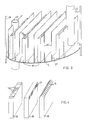
- the structure of the tray 3 is explained in more detail with reference to FIG. 3.
- the gas to be cleaned flows through the channels 18 with a rectangular cross cut (internals) upwards and enters the liquid through the gas outlet openings formed here as holes 19.
- Vertical baffles 20 are arranged between the channels 18. The baffles 20 cause convection flows in the liquid, the liquid flowing upwards in the zones between the gas channels 18 and the baffles 20, releasing the gas escaping from the gas channels 18 at the top, in part thereby flowing laterally over the upper edges of the baffles 20 in the zones between the baffles flow down again and through the gaps 21 directly at the bottom 3 again into the zones between the baffle 20 and gas channel 18.
- This mammoth pump flow running around the guide plates 20 is used for mixing on the trays 3 and for the dispersion of the solids in the liquid (activated sludge!).
- a superimposed cross-flow of the liquid from the inlet pipes 22 or shafts to the outlet pipes 23 also takes place on the floors.
- the seal between the trays 3 and the column wall 24 and the fastening of the trays 3 in the column is known from distillation technology and therefore need not be described in more detail here.
- the gas outlet openings 19 are here as horizontal (left partial image) or vertical slots (middle partial image) or as slot-shaped openings in a roof-shaped closed channel (right partial image). executed.
- Fig. 5 shows a cross section through a floor version with cylindrical gas channels 26, on which bells 27 are fastened, which have slots 19 as gas outlet openings.
- the bells 27 there are concentric guide tubes 28 which leave a gap 29 between the actual base 3 and its lower edge through which the liquid can flow from the liquid zones between the guide tubes 28 and the chimneys 26 or the bells 27.
- the liquid then flows upward, is gassed at the slots 19 and flows over the upper edges of the guide tubes 28 into the zones between the guide tubes and down there again (see flow arrows).
- the liquid flows through the pipe 22 to the bottom and from the upper edge into the pipe 23 again.
- this wall cover can be rinsed off particularly easily by free spraying, as shown in FIG. 6, flushing pipes 30 with spray openings 31 or spray nozzles are introduced perpendicularly to the channels 18 into the gas space beneath the corresponding trays 3 and the gas rise channels are sprayed free if necessary or washed away.
- the number of pipes required can be kept particularly small if they are arranged so that they can be rotated about their longitudinal axis, so that a relatively large channel length can be covered by rotating each spray opening or nozzle.
- the spray openings 31 are each under the gas riser channels 18, so that through Rotation of the flushing pipes running perpendicular to the longitudinal direction of the gas channels allows the entire inside of the gas channels to be sprayed or flushed out.
- correspondingly more pipes are arranged in parallel, the spacing of which depends on the spray width of the nozzles or spray openings 31, which in turn depends on the geometry (channel heights, pipe and spray opening diameter) and on the admission pressure of the flushing liquid.
Landscapes
- Life Sciences & Earth Sciences (AREA)
- Engineering & Computer Science (AREA)
- Environmental & Geological Engineering (AREA)
- Chemical & Material Sciences (AREA)
- Biodiversity & Conservation Biology (AREA)
- Microbiology (AREA)
- Hydrology & Water Resources (AREA)
- Water Supply & Treatment (AREA)
- Organic Chemistry (AREA)
- Health & Medical Sciences (AREA)
- Molecular Biology (AREA)
- Biomedical Technology (AREA)
- Analytical Chemistry (AREA)
- General Chemical & Material Sciences (AREA)
- Oil, Petroleum & Natural Gas (AREA)
- Chemical Kinetics & Catalysis (AREA)
- Treating Waste Gases (AREA)
- Biological Treatment Of Waste Water (AREA)
- Gas Separation By Absorption (AREA)
- Aeration Devices For Treatment Of Activated Polluted Sludge (AREA)
Priority Applications (1)
| Application Number | Priority Date | Filing Date | Title |
|---|---|---|---|
| AT87108345T ATE64584T1 (de) | 1986-06-20 | 1987-06-10 | Verfahren zur biologischen abluft- und abwasserreinigung. |
Applications Claiming Priority (2)
| Application Number | Priority Date | Filing Date | Title |
|---|---|---|---|
| DE3620728 | 1986-06-20 | ||
| DE19863620728 DE3620728A1 (de) | 1986-06-20 | 1986-06-20 | Vorrichtung und verfahren zur biologischen abluft- und abwasserreinigung |
Publications (3)
| Publication Number | Publication Date |
|---|---|
| EP0249861A2 true EP0249861A2 (fr) | 1987-12-23 |
| EP0249861A3 EP0249861A3 (en) | 1989-01-11 |
| EP0249861B1 EP0249861B1 (fr) | 1991-06-19 |
Family
ID=6303355
Family Applications (1)
| Application Number | Title | Priority Date | Filing Date |
|---|---|---|---|
| EP19870108345 Expired - Lifetime EP0249861B1 (fr) | 1986-06-20 | 1987-06-10 | Procédé pour la purification biologique d'air d'échappement et d'eau usée |
Country Status (6)
| Country | Link |
|---|---|
| US (1) | US4869824A (fr) |
| EP (1) | EP0249861B1 (fr) |
| JP (1) | JP2515552B2 (fr) |
| AT (1) | ATE64584T1 (fr) |
| DE (2) | DE3620728A1 (fr) |
| ES (1) | ES2022837B3 (fr) |
Cited By (7)
| Publication number | Priority date | Publication date | Assignee | Title |
|---|---|---|---|---|
| EP0385555A1 (fr) * | 1989-02-28 | 1990-09-05 | Tauw Infra Consult B.V. | Appareil et procédé pour la purification combinée d'air et d'eau |
| EP0442157A1 (fr) * | 1990-02-14 | 1991-08-21 | Tauw Milieu B.V. | Procédé pour la purification d'eau contaminÀ©e et dispositif pour sa mise en oeuvre. |
| WO1992022505A1 (fr) * | 1991-06-08 | 1992-12-23 | Mesroc Gmbh Vertrieb Technischer Produkte | Reacteur a lit fixe pour le traitement biologique des eaux usees |
| WO1995024362A1 (fr) * | 1994-03-08 | 1995-09-14 | Buck-Werke Gmbh & Co. | Procede d'epuration et de reutilisation d'eaux usees contenant des agents tensioactifs |
| WO2007135087A1 (fr) * | 2006-05-23 | 2007-11-29 | Otv Sa | Dispositif d'aeration pour systeme de filtration d'eau a membranes immergees, incluant un plancher pourvu de moyens d'injection d'un gaz et d'au moins un systeme d'equilibrage des pressions |
| EP2826543A1 (fr) * | 2013-07-16 | 2015-01-21 | Vilniaus Gedimino technikos universitetas | Biofiltre-absorbant |
| CN112387039A (zh) * | 2020-11-29 | 2021-02-23 | 河南基兆建筑工程有限公司 | 一种隧道洞口用可空气回流的纵向多腔式防污装置 |
Families Citing this family (13)
| Publication number | Priority date | Publication date | Assignee | Title |
|---|---|---|---|---|
| US5232676A (en) * | 1990-08-10 | 1993-08-03 | Bayer Aktiengesellschaft | Process for the biological purification of waste air streams |
| DE4127267C2 (de) * | 1991-08-17 | 1994-10-06 | Degussa | Verfahren zur biologischen Abluftreinigung |
| US5387344A (en) * | 1992-11-13 | 1995-02-07 | Monsanto Enviro-Chem Systems, Inc. | Process for treating waste water oxidation ponds to abate malodors |
| DE69405165T2 (de) * | 1993-06-24 | 1998-01-02 | Boc Gases Australia Ltd | Verfahren und Vorrichtung zur gesteuerten biologischen Abwasseraufbereitung |
| JP3107950B2 (ja) * | 1993-07-07 | 2000-11-13 | オルガノ株式会社 | 生物処理装置、及び同装置を用いた水処理方法 |
| JPH10500351A (ja) * | 1994-03-16 | 1998-01-13 | ヴァポ オイ | ガス類を精製する方法と装置 |
| US6019817A (en) * | 1998-02-25 | 2000-02-01 | Agri Microbe Sales, L.C. | System and method for capturing and destroying HAP/VOC substances using microbial degradation |
| EP0960648A1 (fr) * | 1998-05-27 | 1999-12-01 | D.I. Wieser-Linhart, Emil A.J. | Procédé et installation pour purifier le gaz d'échappement d' un sécheur |
| US6461510B1 (en) | 1999-07-23 | 2002-10-08 | Tennessee Valley Authority | High-efficiency processes for destruction of contaminants |
| US8852924B2 (en) * | 2009-04-02 | 2014-10-07 | Chingoo Research Partnership | Algae photobioreactor |
| CN102849844B (zh) * | 2012-10-10 | 2014-12-10 | 南京大学 | 一种耦合生物反应器及其同时净化恶臭气体和废水的方法 |
| CN106110878A (zh) * | 2016-08-31 | 2016-11-16 | 北京北林绿源生态技术研究院有限责任公司 | 废气净化单元装置及废气净化系统 |
| CN112620232A (zh) * | 2020-12-10 | 2021-04-09 | 华菱安赛乐米塔尔汽车板有限公司 | 一种降低酸再生氯化亚铁洗涤塔填料结垢的工艺方法 |
Citations (3)
| Publication number | Priority date | Publication date | Assignee | Title |
|---|---|---|---|---|
| DE1542274A1 (de) * | 1966-07-06 | 1970-03-26 | Koppers Gmbh Heinrich | Verfahren und Vorrichtung zur Durchfuehrung langsam verlaufender chemischer Reaktionen von Gasen mit Fluessigkeiten |
| DE2334107A1 (de) * | 1973-07-04 | 1975-01-23 | Siemens Ag | Verfahren zur biologischen reinigung von mit organischen und/oder anorganischen feststoffen verunreinigten abwaessern durch gleich- oder gegenstromwaesche in lochsteintuermen |
| DE2554169A1 (de) * | 1975-12-02 | 1976-12-09 | Menzel & Co | Verfahren zur aeroben behandlung von fluessigen abfallstoffen |
Family Cites Families (18)
| Publication number | Priority date | Publication date | Assignee | Title |
|---|---|---|---|---|
| US2600710A (en) * | 1947-11-15 | 1952-06-17 | Henry N Wade | Bubble cap for washing gases and vapors |
| US3070359A (en) * | 1958-05-29 | 1962-12-25 | Gerard P Canevari | Vapor-liquid contacting apparatus |
| FR1373686A (fr) * | 1963-06-10 | 1964-10-02 | Houilleres Bassin Du Nord | Plateau perfectionné pour colonnes de contact gaz-liquide |
| FR94413E (fr) * | 1967-10-26 | 1969-08-14 | Sadoulet Maurice Alfred Alexan | Épurateur pour effluents de fosse septique. |
| US4100063A (en) * | 1972-07-20 | 1978-07-11 | Maschinenfabrik Hellmut Geiger | Method and apparatus for the biological cleansing of waste water |
| CA1033153A (fr) * | 1972-10-12 | 1978-06-20 | Raymond J. Mcgowan | Methode et materiel pour le transfert thermique de masse |
| DE2553050A1 (de) * | 1975-11-26 | 1977-06-16 | Baensch Tetra Werke | Geraet und verfahren zur austreibung von im wasser geloesten verunreinigungen, hauptsaechlich nitraten |
| JPS53113267A (en) * | 1977-03-15 | 1978-10-03 | Chiyoda Chem Eng & Constr Co Ltd | Gas-liquid contacting apparatus |
| DE2953476A1 (de) * | 1978-11-22 | 1986-04-10 | Geoffrey Gordon Leeds Yorkshire Haselden | Destillationsplatte |
| JPS5816956B2 (ja) * | 1979-02-21 | 1983-04-04 | 大和設備工事株式会社 | 汚液の合併処理浄化装置 |
| US4305895A (en) * | 1979-03-02 | 1981-12-15 | Heath Rodney T | Bubble cap and riser construction |
| US4279842A (en) * | 1979-07-26 | 1981-07-21 | Houston Systems Manufacturing Co., Inc. | Air diffuser assembly |
| FR2473351A1 (fr) * | 1980-01-09 | 1981-07-17 | Degremont Sa | Dispositif d'introduction de gaz dans un liquide |
| US4510023A (en) * | 1983-06-17 | 1985-04-09 | Air Products And Chemicals, Inc. | Perforated bubble caps for enhanced vapor/liquid contact on a distillation tray |
| JPS607924A (ja) * | 1983-06-28 | 1985-01-16 | Fuji Kasui Kogyo Kk | 排ガス処理方法 |
| NL8303031A (nl) * | 1983-08-31 | 1985-03-18 | Tongeren Ingbureau Bv Van | Werkwijze en inrichting voor het biologisch filtreren van gassen. |
| FR2557558B1 (fr) * | 1984-01-02 | 1986-05-23 | Degremont Sa | Filtre immerge a remplissage de materiau granulaire |
| DE3412394C1 (de) * | 1984-04-03 | 1985-11-07 | Didier-Werke Ag, 6200 Wiesbaden | Verfahren und Vorrichtung zum Reinigen von Belüftungskerzen |
-
1986
- 1986-06-20 DE DE19863620728 patent/DE3620728A1/de not_active Withdrawn
-
1987
- 1987-06-10 DE DE8787108345T patent/DE3770877D1/de not_active Expired - Lifetime
- 1987-06-10 EP EP19870108345 patent/EP0249861B1/fr not_active Expired - Lifetime
- 1987-06-10 ES ES87108345T patent/ES2022837B3/es not_active Expired - Lifetime
- 1987-06-10 AT AT87108345T patent/ATE64584T1/de active
- 1987-06-18 JP JP15037387A patent/JP2515552B2/ja not_active Expired - Lifetime
-
1988
- 1988-12-08 US US07/283,008 patent/US4869824A/en not_active Expired - Fee Related
Patent Citations (3)
| Publication number | Priority date | Publication date | Assignee | Title |
|---|---|---|---|---|
| DE1542274A1 (de) * | 1966-07-06 | 1970-03-26 | Koppers Gmbh Heinrich | Verfahren und Vorrichtung zur Durchfuehrung langsam verlaufender chemischer Reaktionen von Gasen mit Fluessigkeiten |
| DE2334107A1 (de) * | 1973-07-04 | 1975-01-23 | Siemens Ag | Verfahren zur biologischen reinigung von mit organischen und/oder anorganischen feststoffen verunreinigten abwaessern durch gleich- oder gegenstromwaesche in lochsteintuermen |
| DE2554169A1 (de) * | 1975-12-02 | 1976-12-09 | Menzel & Co | Verfahren zur aeroben behandlung von fluessigen abfallstoffen |
Cited By (8)
| Publication number | Priority date | Publication date | Assignee | Title |
|---|---|---|---|---|
| EP0385555A1 (fr) * | 1989-02-28 | 1990-09-05 | Tauw Infra Consult B.V. | Appareil et procédé pour la purification combinée d'air et d'eau |
| EP0442157A1 (fr) * | 1990-02-14 | 1991-08-21 | Tauw Milieu B.V. | Procédé pour la purification d'eau contaminÀ©e et dispositif pour sa mise en oeuvre. |
| WO1992022505A1 (fr) * | 1991-06-08 | 1992-12-23 | Mesroc Gmbh Vertrieb Technischer Produkte | Reacteur a lit fixe pour le traitement biologique des eaux usees |
| WO1995024362A1 (fr) * | 1994-03-08 | 1995-09-14 | Buck-Werke Gmbh & Co. | Procede d'epuration et de reutilisation d'eaux usees contenant des agents tensioactifs |
| WO2007135087A1 (fr) * | 2006-05-23 | 2007-11-29 | Otv Sa | Dispositif d'aeration pour systeme de filtration d'eau a membranes immergees, incluant un plancher pourvu de moyens d'injection d'un gaz et d'au moins un systeme d'equilibrage des pressions |
| EP2826543A1 (fr) * | 2013-07-16 | 2015-01-21 | Vilniaus Gedimino technikos universitetas | Biofiltre-absorbant |
| CN112387039A (zh) * | 2020-11-29 | 2021-02-23 | 河南基兆建筑工程有限公司 | 一种隧道洞口用可空气回流的纵向多腔式防污装置 |
| CN112387039B (zh) * | 2020-11-29 | 2022-09-09 | 河南基兆建筑工程有限公司 | 一种隧道洞口用可空气回流的纵向多腔式防污装置 |
Also Published As
| Publication number | Publication date |
|---|---|
| JP2515552B2 (ja) | 1996-07-10 |
| DE3770877D1 (de) | 1991-07-25 |
| ES2022837B3 (es) | 1991-12-16 |
| JPS634831A (ja) | 1988-01-09 |
| US4869824A (en) | 1989-09-26 |
| DE3620728A1 (de) | 1987-12-23 |
| EP0249861A3 (en) | 1989-01-11 |
| ATE64584T1 (de) | 1991-07-15 |
| EP0249861B1 (fr) | 1991-06-19 |
Similar Documents
| Publication | Publication Date | Title |
|---|---|---|
| EP0249861B1 (fr) | Procédé pour la purification biologique d'air d'échappement et d'eau usée | |
| EP0306053B1 (fr) | Réacteur et procédé pour la purification biologique d'eau polluée | |
| DE102006053910B4 (de) | Biowäscher | |
| DE102007050904B4 (de) | Anlage und Verfahren zur Reinigung von Rauchgasen | |
| DE19516660C2 (de) | Verfahren und Einrichtung mit gasbeschichteter Siebplatte zur nassen Entschwefelung von Rauchgas | |
| DE2705903A1 (de) | Horizontale gas-spruehreinigungsvorrichtung | |
| EP0355022A1 (fr) | Dispositif et procédé traitement microbiologique d'eau | |
| EP0328758B1 (fr) | Procédé et dispositif pour la purification biologique de gaz d'échappement | |
| EP0094573B1 (fr) | Dispositif pour l'épuration de l'air d'évacuation | |
| EP0470468B1 (fr) | Procédé de nettoyage biologique d'air d'échappement | |
| EP1328332B1 (fr) | Installation d'epuration de rejets gazeux | |
| DE3503723C2 (fr) | ||
| DE69002348T2 (de) | Vorrichtung und verfahren fuer eine kombinierte luft- und wasserreinigung. | |
| DE3126078C2 (de) | Vorrichtung zur Abwasserreinigung | |
| EP0902761B1 (fr) | Station d'epuration pour traitement des eaux | |
| DE19631796A1 (de) | Verfahren und Vorrichtung zur Reinigung von Abwassern | |
| EP0739860A1 (fr) | Procédé et dispositif pour le traitement biologique de l'eau usée | |
| EP0162121B1 (fr) | Clarificateur pour la purification biologique d'eaux usées | |
| EP0161520B1 (fr) | Procédé et dispositif pour la désulfuration de gaz de fumée | |
| DE29521085U1 (de) | Festbett-Bioreaktor zur anaeroben Behandlung von Abwässern | |
| EP1670723B1 (fr) | Procede de purification biologique d'eaux usees | |
| DE4240062C1 (de) | Festbettreaktor zur biologischen Behandlung von Abwasser | |
| AT409724B (de) | Verfahrens- und anlagenkombination zur reinigung von staub-, aerosol- und geruchsbeladener abluft | |
| EP0162831A1 (fr) | Appareil pour le traitement d'eau usée | |
| DE3244962C1 (de) | Verfahren und Vorrichtung zur Abwasserreinigung |
Legal Events
| Date | Code | Title | Description |
|---|---|---|---|
| PUAI | Public reference made under article 153(3) epc to a published international application that has entered the european phase |
Free format text: ORIGINAL CODE: 0009012 |
|
| 17P | Request for examination filed |
Effective date: 19870610 |
|
| AK | Designated contracting states |
Kind code of ref document: A2 Designated state(s): AT BE CH DE ES FR GB IT LI NL SE |
|
| RIN1 | Information on inventor provided before grant (corrected) |
Inventor name: BARTH, OTTO Inventor name: STRACKE, HUBERT, DR. Inventor name: MELIN, THOMAS, DR. |
|
| PUAL | Search report despatched |
Free format text: ORIGINAL CODE: 0009013 |
|
| AK | Designated contracting states |
Kind code of ref document: A3 Designated state(s): AT BE CH DE ES FR GB IT LI NL SE |
|
| 17Q | First examination report despatched |
Effective date: 19890908 |
|
| GRAA | (expected) grant |
Free format text: ORIGINAL CODE: 0009210 |
|
| AK | Designated contracting states |
Kind code of ref document: B1 Designated state(s): AT BE CH DE ES FR GB IT LI NL SE |
|
| REF | Corresponds to: |
Ref document number: 64584 Country of ref document: AT Date of ref document: 19910715 Kind code of ref document: T |
|
| ITF | It: translation for a ep patent filed | ||
| REF | Corresponds to: |
Ref document number: 3770877 Country of ref document: DE Date of ref document: 19910725 |
|
| ET | Fr: translation filed | ||
| GBT | Gb: translation of ep patent filed (gb section 77(6)(a)/1977) | ||
| PLBE | No opposition filed within time limit |
Free format text: ORIGINAL CODE: 0009261 |
|
| STAA | Information on the status of an ep patent application or granted ep patent |
Free format text: STATUS: NO OPPOSITION FILED WITHIN TIME LIMIT |
|
| 26N | No opposition filed | ||
| EAL | Se: european patent in force in sweden |
Ref document number: 87108345.7 |
|
| PGFP | Annual fee paid to national office [announced via postgrant information from national office to epo] |
Ref country code: DE Payment date: 19970516 Year of fee payment: 11 |
|
| PGFP | Annual fee paid to national office [announced via postgrant information from national office to epo] |
Ref country code: SE Payment date: 19970522 Year of fee payment: 11 |
|
| PGFP | Annual fee paid to national office [announced via postgrant information from national office to epo] |
Ref country code: FR Payment date: 19970528 Year of fee payment: 11 |
|
| PGFP | Annual fee paid to national office [announced via postgrant information from national office to epo] |
Ref country code: GB Payment date: 19970602 Year of fee payment: 11 |
|
| PGFP | Annual fee paid to national office [announced via postgrant information from national office to epo] |
Ref country code: ES Payment date: 19970609 Year of fee payment: 11 Ref country code: CH Payment date: 19970609 Year of fee payment: 11 |
|
| PGFP | Annual fee paid to national office [announced via postgrant information from national office to epo] |
Ref country code: AT Payment date: 19970620 Year of fee payment: 11 |
|
| PGFP | Annual fee paid to national office [announced via postgrant information from national office to epo] |
Ref country code: BE Payment date: 19970626 Year of fee payment: 11 |
|
| PGFP | Annual fee paid to national office [announced via postgrant information from national office to epo] |
Ref country code: NL Payment date: 19970630 Year of fee payment: 11 |
|
| PG25 | Lapsed in a contracting state [announced via postgrant information from national office to epo] |
Ref country code: GB Free format text: LAPSE BECAUSE OF NON-PAYMENT OF DUE FEES Effective date: 19980610 Ref country code: AT Free format text: LAPSE BECAUSE OF NON-PAYMENT OF DUE FEES Effective date: 19980610 |
|
| PG25 | Lapsed in a contracting state [announced via postgrant information from national office to epo] |
Ref country code: SE Free format text: LAPSE BECAUSE OF NON-PAYMENT OF DUE FEES Effective date: 19980611 Ref country code: ES Free format text: LAPSE BECAUSE OF NON-PAYMENT OF DUE FEES Effective date: 19980611 |
|
| PG25 | Lapsed in a contracting state [announced via postgrant information from national office to epo] |
Ref country code: LI Free format text: LAPSE BECAUSE OF NON-PAYMENT OF DUE FEES Effective date: 19980630 Ref country code: CH Free format text: LAPSE BECAUSE OF NON-PAYMENT OF DUE FEES Effective date: 19980630 Ref country code: BE Free format text: LAPSE BECAUSE OF NON-PAYMENT OF DUE FEES Effective date: 19980630 |
|
| BERE | Be: lapsed |
Owner name: BAYER A.G. Effective date: 19980630 |
|
| PG25 | Lapsed in a contracting state [announced via postgrant information from national office to epo] |
Ref country code: NL Free format text: LAPSE BECAUSE OF NON-PAYMENT OF DUE FEES Effective date: 19990101 |
|
| GBPC | Gb: european patent ceased through non-payment of renewal fee |
Effective date: 19980610 |
|
| REG | Reference to a national code |
Ref country code: CH Ref legal event code: PL |
|
| PG25 | Lapsed in a contracting state [announced via postgrant information from national office to epo] |
Ref country code: FR Free format text: LAPSE BECAUSE OF NON-PAYMENT OF DUE FEES Effective date: 19990226 |
|
| EUG | Se: european patent has lapsed |
Ref document number: 87108345.7 |
|
| NLV4 | Nl: lapsed or anulled due to non-payment of the annual fee |
Effective date: 19990101 |
|
| PG25 | Lapsed in a contracting state [announced via postgrant information from national office to epo] |
Ref country code: DE Free format text: LAPSE BECAUSE OF NON-PAYMENT OF DUE FEES Effective date: 19990401 |
|
| REG | Reference to a national code |
Ref country code: FR Ref legal event code: ST |
|
| REG | Reference to a national code |
Ref country code: ES Ref legal event code: FD2A Effective date: 20000503 |
|
| PG25 | Lapsed in a contracting state [announced via postgrant information from national office to epo] |
Ref country code: IT Free format text: LAPSE BECAUSE OF NON-PAYMENT OF DUE FEES;WARNING: LAPSES OF ITALIAN PATENTS WITH EFFECTIVE DATE BEFORE 2007 MAY HAVE OCCURRED AT ANY TIME BEFORE 2007. THE CORRECT EFFECTIVE DATE MAY BE DIFFERENT FROM THE ONE RECORDED. Effective date: 20050610 |