EP0872986A2 - Elektronisches Gerät, Verfahren zur Informationsübertragung und Speichermedium - Google Patents
Elektronisches Gerät, Verfahren zur Informationsübertragung und Speichermedium Download PDFInfo
- Publication number
- EP0872986A2 EP0872986A2 EP19980302679 EP98302679A EP0872986A2 EP 0872986 A2 EP0872986 A2 EP 0872986A2 EP 19980302679 EP19980302679 EP 19980302679 EP 98302679 A EP98302679 A EP 98302679A EP 0872986 A2 EP0872986 A2 EP 0872986A2
- Authority
- EP
- European Patent Office
- Prior art keywords
- information
- amount
- command
- unit
- ieee
- Prior art date
- Legal status (The legal status is an assumption and is not a legal conclusion. Google has not performed a legal analysis and makes no representation as to the accuracy of the status listed.)
- Granted
Links
Images


Classifications
-
- H—ELECTRICITY
- H04—ELECTRIC COMMUNICATION TECHNIQUE
- H04L—TRANSMISSION OF DIGITAL INFORMATION, e.g. TELEGRAPHIC COMMUNICATION
- H04L12/00—Data switching networks
- H04L12/28—Data switching networks characterised by path configuration, e.g. LAN [Local Area Networks] or WAN [Wide Area Networks]
- H04L12/40—Bus networks
- H04L12/40052—High-speed IEEE 1394 serial bus
- H04L12/40058—Isochronous transmission
-
- H—ELECTRICITY
- H04—ELECTRIC COMMUNICATION TECHNIQUE
- H04N—PICTORIAL COMMUNICATION, e.g. TELEVISION
- H04N7/00—Television systems
- H04N7/20—Adaptations for transmission via a GHz frequency band, e.g. via satellite
-
- H—ELECTRICITY
- H04—ELECTRIC COMMUNICATION TECHNIQUE
- H04L—TRANSMISSION OF DIGITAL INFORMATION, e.g. TELEGRAPHIC COMMUNICATION
- H04L12/00—Data switching networks
- H04L12/28—Data switching networks characterised by path configuration, e.g. LAN [Local Area Networks] or WAN [Wide Area Networks]
- H04L12/40—Bus networks
- H04L12/40052—High-speed IEEE 1394 serial bus
- H04L12/40117—Interconnection of audio or video/imaging devices
-
- H—ELECTRICITY
- H04—ELECTRIC COMMUNICATION TECHNIQUE
- H04L—TRANSMISSION OF DIGITAL INFORMATION, e.g. TELEGRAPHIC COMMUNICATION
- H04L47/00—Traffic control in data switching networks
- H04L47/10—Flow control; Congestion control
-
- H—ELECTRICITY
- H04—ELECTRIC COMMUNICATION TECHNIQUE
- H04L—TRANSMISSION OF DIGITAL INFORMATION, e.g. TELEGRAPHIC COMMUNICATION
- H04L47/00—Traffic control in data switching networks
- H04L47/10—Flow control; Congestion control
- H04L47/13—Flow control; Congestion control in a LAN segment, e.g. ring or bus
-
- H—ELECTRICITY
- H04—ELECTRIC COMMUNICATION TECHNIQUE
- H04L—TRANSMISSION OF DIGITAL INFORMATION, e.g. TELEGRAPHIC COMMUNICATION
- H04L47/00—Traffic control in data switching networks
- H04L47/10—Flow control; Congestion control
- H04L47/30—Flow control; Congestion control in combination with information about buffer occupancy at either end or at transit nodes
-
- H—ELECTRICITY
- H04—ELECTRIC COMMUNICATION TECHNIQUE
- H04N—PICTORIAL COMMUNICATION, e.g. TELEVISION
- H04N21/00—Selective content distribution, e.g. interactive television or video on demand [VOD]
- H04N21/40—Client devices specifically adapted for the reception of or interaction with content, e.g. set-top-box [STB]; Operations thereof
- H04N21/43—Processing of content or additional data, e.g. demultiplexing additional data from a digital video stream; Elementary client operations, e.g. monitoring of home network or synchronising decoder's clock; Client middleware
- H04N21/436—Interfacing a local distribution network, e.g. communicating with another STB or one or more peripheral devices inside the home
- H04N21/43615—Interfacing a Home Network, e.g. for connecting the client to a plurality of peripherals
-
- H—ELECTRICITY
- H04—ELECTRIC COMMUNICATION TECHNIQUE
- H04N—PICTORIAL COMMUNICATION, e.g. TELEVISION
- H04N21/00—Selective content distribution, e.g. interactive television or video on demand [VOD]
- H04N21/40—Client devices specifically adapted for the reception of or interaction with content, e.g. set-top-box [STB]; Operations thereof
- H04N21/43—Processing of content or additional data, e.g. demultiplexing additional data from a digital video stream; Elementary client operations, e.g. monitoring of home network or synchronising decoder's clock; Client middleware
- H04N21/436—Interfacing a local distribution network, e.g. communicating with another STB or one or more peripheral devices inside the home
- H04N21/4363—Adapting the video or multiplex stream to a specific local network, e.g. a IEEE 1394 or Bluetooth® network
- H04N21/43632—Adapting the video or multiplex stream to a specific local network, e.g. a IEEE 1394 or Bluetooth® network involving a wired protocol, e.g. IEEE 1394
-
- H—ELECTRICITY
- H04—ELECTRIC COMMUNICATION TECHNIQUE
- H04N—PICTORIAL COMMUNICATION, e.g. TELEVISION
- H04N21/00—Selective content distribution, e.g. interactive television or video on demand [VOD]
- H04N21/40—Client devices specifically adapted for the reception of or interaction with content, e.g. set-top-box [STB]; Operations thereof
- H04N21/43—Processing of content or additional data, e.g. demultiplexing additional data from a digital video stream; Elementary client operations, e.g. monitoring of home network or synchronising decoder's clock; Client middleware
- H04N21/442—Monitoring of processes or resources, e.g. detecting the failure of a recording device, monitoring the downstream bandwidth, the number of times a movie has been viewed, the storage space available from the internal hard disk
- H04N21/44231—Monitoring of peripheral device or external card, e.g. to detect processing problems in a handheld device or the failure of an external recording device
-
- H—ELECTRICITY
- H04—ELECTRIC COMMUNICATION TECHNIQUE
- H04L—TRANSMISSION OF DIGITAL INFORMATION, e.g. TELEGRAPHIC COMMUNICATION
- H04L47/00—Traffic control in data switching networks
- H04L47/10—Flow control; Congestion control
- H04L47/43—Assembling or disassembling of packets, e.g. segmentation and reassembly [SAR]
Definitions
- the present invention relates to electronic apparatus, information transmitting method thereof, and storing medium.
- An embodiment of the invention concerns an electronic unit for use with for example an IEEE 1394 serial bus, and to a method of transmitting for example a large amount of data using an asynchronous packet.
- a communication system that connects electronic units (hereinafter referred to as units) such as a personal computer, a digital video cassette recorder (hereinafter referred to as DVCR), and a digital television receiver with an IEEE 1394 serial bus and that sends/receives packets of a digital video signal, a digital audio signal, and a control signal therebetween has been proposed.
- units electronic units
- DVCR digital video cassette recorder
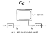
- Fig. 1 shows an example of such a communication system.
- the communication system comprises a monitor 11, a DVCR 12, and a tuner 13 as units.
- the monitor 11 and the DVCR 12 are connected with an IEEE 1394 serial bus cable 14.
- the monitor 11 and the tuber 13 are connected with an IEEE 1394 serial bus cable 15.
- an isochronous communication for periodically transmitting real time data such as a digital video signal and a digital audio signal between units and an ASYNCHRONOUS communication (ASYNC communication) for non-periodically transmitting commands such as a unit operation control command and a unit connection control command
- ISO communication real time data
- ASYNC communication ASYNCHRONOUS communication
- commands such as a unit operation control command and a unit connection control command
- a digital video signal and a digital audio signal selected by the tuner 13 can be reproduced as video information and audio information by the monitor 11.
- such signals can be recorded by the DVCR 12.
- a channel selection control command of the tuner 13, an operation mode setup command of the DVCR 12, and so forth can be sent from the monitor 11 to the relevant units through the IEEE 1394 serial bus cables 14 and 15.
- AV/C Audio Visual/Control
- AV/C command set a status command for inquiring a status has been defined.
- status information of a designated unit that is sent back as an operand has been defined.
- the data amount of the state may be very large.
- a television broadcast has a hierarchical structure composed of a network layer, a multiplex layer, a service layer, and a component layer.
- the data amount of a status command for inquiring each service (broadcast channel) that the digital broadcast tuner is currently selecting may exceed 30 bytes.
- a plurality of services can be placed on one stream.
- a response to an inquiry is required for a plurality of services. Consequently, the data amount of one response may become several hundred bytes.
- An embodiment of the present invention seeks to provide a unit that allows a large amount of data that exceeds the size of a buffer thereof to be obtained and an information transmitting method thereof.
- One aspect of the present invention provides a method for transmitting information between electronic units, comprising the steps of (a) transmitting information whose amount does not exceed a predetermined data amount, (b) determining whether or not the predetermined data amount is larger than a desired information amount, (c) when the determined result at step (b) is No, transmitting remaining information for the predetermined amount or less, and (d) repeating the steps (a) to (c) until there is no remaining information.
- Another aspect of the present invention provides an electronic unit for communicating with a plurality of units, comprising first means for physically communicating with the plurality of units, buffer means for temporarily storing data that is transmitted by the first means; and controlling means for controlling the first means and the buffer means, wherein the controlling means transmits information whose amount does not exceed a predetermined data amount, determines whether or not the predetermined data amount is larger than a desired information amount, when the determined result is No, transmits remaining information for the predetermined amount or less, and repeats these operations until there is no remaining information.
- a further aspect of the present invention provides a storage medium storing a program for an electronic unit for communicating with a plurality of units, comprising first means for physically communicating with the plurality of units, buffer means for temporarily storing data that is transmitted by the first means, and controlling means for controlling the first means and the buffer means, the program causing the controlling means to perform the functions of (a) transmitting information whose amount does not exceed a predetermined data amount, (b) determining whether or not the predetermined data amount is larger than a desired information amount, (c) when the determined result at step (b) is No, transmitting remaining information for the predetermined amount or less, and (d) repeating the steps (a) to (c) until there is no remaining information.
- Fig. 3 is a block diagram showing the structure of principal portions of an illustrative DVCR according to the present invention.
- the DVCR comprises a tuner sub- unit 1, a controller 5, a memory 6, and an IEEE 1394 ASYNC block 7.
- the tuner sub-unit 1 has an analog broadcast tuner 2 and a digital broadcast tuner 3.
- the analog broadcast tuner 2 receive a television broadcast signal through an antenna (ANT) 1.
- the digital broadcast tuner 3 receives a television broadcast signal through an antenna (ANT) 2.
- a signal of a channel selected by the analog broadcast tuner 2 is sent to a recording portion (DVCR sub-unit) through a sub-unit output plug P1.
- a stream from a transponder selected by the digital broadcast tuner 3 is sent to a demultiplexer 4.
- the demultiplexer 4 selects at least one service and sends the selected service to a recording portion and an IEEE 1394 ISO block through a sub-unit output plug P0.
- the demultiplexer 4 branches service information of the stream to the controller 5.
- the sub-unit output plugs P0 and P1 are output terminals in the logical meaning and it is not required that they are physical output plugs.
- the controller 5 controls the entire DVCR.
- the controller 5 creates an object list corresponding to service information received from the demultiplexer 4 and writes the object list to the memory 6.
- the controller 5 sends/receives a command and response to/from another unit through the IEEE 1394 ASYNC block 7 and an IEEE 1394 serial bus 8.
- the controller 5 writes information of signals that are currently being output from the sub-unit output plugs P0 and P1 to the memory 6.
- the memory 6 has a particular area referred to as a descriptor as shown in Fig. 4.
- a descriptor As shown in Fig. 4.
- the above-mentioned object list and information of signals that are currently being output are written.
- Fig. 5 shows an example of the object list.
- the object list is created corresponding to the multiplex layer, the service layer, and the component layer shown in Fig. 1.
- Fig. 6A shows the structure of a list (plug list) that shows plugs of the tuner sub-unit and objects that are currently being output from these plugs. This list is referred to as plug tuner object list.
- Fig. 6B shows a real example of the plug tuner object list.
- there are two types of object entry describing method As shown in Fig. 6B, there are two types of object entry describing method. The first method is a detailed type for describing specifications in detail. The second method is a reference type for referencing another list.
- the IEEE 1394 ASYNC block 7 assembles a command and a response created by the IEEE 1394 ASYNC block 7 as an ASYNC packet and sends the ASYNC packet to the IEEE 1394 serial bus 8.
- the IEEE 1394 ASYNC block 7 disassembles an ASYNC packet received from the IEEE 1394 serial bus 8 into a command and a response and sends the command and the response to the controller 5.
- the command and the response are temporarily stored in the buffer memory (that has a transmission buffer and a reception buffer).
- Direct Select Object command as a tuner sub-unit command selects at least one service, multiplexed stream, or component that is being broadcast and outputs the selected service, multiplexed stream, or component to a designated sub-unit plug.
- a control command designates the selection.
- a status command inquires what is currently being selected.
- Fig. 7 shows the structure of a control command.
- source_plug represents an output plug of the tuner sub-unit.
- subfunction removes, appends, or replaces a designated object of a designated plug.
- tuner_object_selection_specification is a parameter necessary for selection. It is supposed that the amount of information of tuner_object_selection_specification is around 10 to 50 bytes.
- Fig. 8 shows Direct Select Object status command.
- the Direct Select Object status command inquires what is currently being output to a designate plug.
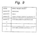
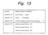
- Fig. 9 shows a response of the Direct Select Object status command.
- the Direct Select Object status command is transmitted.
- another unit for example, the monitor unit connected to the IEEE 1394 serial bus 8 shown in Fig. 3 places a command as shown in Fig. 8 in an ASYNC packet and sends the resultant ASYNC packet to the IEEE 1394 serial bus 8 through the IEEE 1394 ASYNC block.
- the packet is input to the IEEE 1394 ASYNC block 7 shown in Fig. 3.
- the packet is temporarily stored in the buffer memory 9 and then read by the controller 5.
- the controller 5 analyzes the received command and checks signals that are currently being output to a designated plug (in this case, the sub-unit plug P0). In other words, the controller 5 checks information of signals that are currently being output with the descriptor stored in the memory 6. As exemplified in Figs. 6A and 6B, the information describes the number of entries of objects for each plug. Thus, the controller 5 reads information of the plug P0, creates a response with the structure shown in Fig. 9, and sends the response back to the relevant unit.
- the content of the response depends on the size of the buffer memory 9 of the IEEE 1394 ASYNC block 7 and the full length of tuner_object_selection_specification in the response.
- the size of one tuner_object_selection_specification is 30 bytes and four objects are currently being output to the plug P0, the total amount of data of the response becomes 120 bytes.
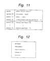
- the controller sends a response as shown in Fig. 11 back to the relevant unit.
- operand [0] is stable.
- operand [3] to [x] information of four selection_specification [0] to [4] is sent back to the relevant unit.
- Fig. 12 shows an example of the content of each selection_specification.
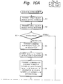
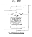
- An ASYNC packet containing the response is received by the command transmitter unit through the IEEE 1394 serial bus 8 (at step S2).
- the response is sent to the controller through the IEEE 1394 ASYNC block of the command transmitter unit.
- the controller references the status field of the response (at step S3).
- the command transmitter unit completes the process.
- the response contains information of objects that can be sent back as shown in Fig. 13.
- information of signals that are currently being output is read from the descriptor stored in the memory 6.
- a process for a packet transmitted between a command transmitter unit and a command receiver unit (the DVCR shown in Fig. 3) is omitted.
- the command transmitter unit sends a command for reading a plug list of the descriptor (at step S4).
- the controller 5 of the command receiver unit reads the plug list as shown in Figs. 6A and 6B from the descriptor stored in the memory 6 and sends the plug list as a response to the command transmitter unit.
- data_length 0 of operand [5] represents that the command transmitter unit requires to read all objects with an entry number k.
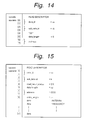
- Fig. 15 shows an example of the structure of a response to the command shown in Fig. 14.
- entry_length of operand [8] represents the length of the object with the entry number k.
- the size of the transmission buffer in the buffer memory 9 of the IEEE 1394 ASYNC block 7 shown in Fig. 3 is 100 bytes and the entry length is 30 bytes, information of one entry can be sent with one response.
- the size of the transmission buffer of the buffer memory 9 is smaller than 30 bytes, (for example, the size is 10 bytes)
- the offset address is shifted by 10 bytes and sent as three responses.
- the command receiver unit when the command receiver unit cannot send to the command transmitter unit a response with information required by the command transmitter unit, the command receiver unit sends information of the maximum bytes that the command receiver unit can handle back to the command transmitter unit.
- the command transmitter unit can freely designate an address and data length, it can send large amount of data with a plurality of responses.
- a large amount of data that exceeds the buffer size can be extracted.
Priority Applications (1)
| Application Number | Priority Date | Filing Date | Title |
|---|---|---|---|
| EP20050077005 EP1601142B1 (de) | 1997-04-15 | 1998-04-06 | Elektronisches Gerät, Verfahren zur Informationsübertragung und Speichermedium |
Applications Claiming Priority (3)
| Application Number | Priority Date | Filing Date | Title |
|---|---|---|---|
| JP9687497 | 1997-04-15 | ||
| JP9687497A JP3658919B2 (ja) | 1997-04-15 | 1997-04-15 | 電子機器及びその情報伝送方法 |
| JP96874/97 | 1997-04-15 |
Related Child Applications (1)
| Application Number | Title | Priority Date | Filing Date |
|---|---|---|---|
| EP20050077005 Division EP1601142B1 (de) | 1997-04-15 | 1998-04-06 | Elektronisches Gerät, Verfahren zur Informationsübertragung und Speichermedium |
Publications (3)
| Publication Number | Publication Date |
|---|---|
| EP0872986A2 true EP0872986A2 (de) | 1998-10-21 |
| EP0872986A3 EP0872986A3 (de) | 1999-11-17 |
| EP0872986B1 EP0872986B1 (de) | 2008-05-14 |
Family
ID=14176579
Family Applications (2)
| Application Number | Title | Priority Date | Filing Date |
|---|---|---|---|
| EP19980302679 Expired - Lifetime EP0872986B1 (de) | 1997-04-15 | 1998-04-06 | Elektronisches Gerät, Verfahren zur Informationsübertragung und Speichermedium |
| EP20050077005 Expired - Lifetime EP1601142B1 (de) | 1997-04-15 | 1998-04-06 | Elektronisches Gerät, Verfahren zur Informationsübertragung und Speichermedium |
Family Applications After (1)
| Application Number | Title | Priority Date | Filing Date |
|---|---|---|---|
| EP20050077005 Expired - Lifetime EP1601142B1 (de) | 1997-04-15 | 1998-04-06 | Elektronisches Gerät, Verfahren zur Informationsübertragung und Speichermedium |
Country Status (12)
| Country | Link |
|---|---|
| US (2) | US6055589A (de) |
| EP (2) | EP0872986B1 (de) |
| JP (1) | JP3658919B2 (de) |
| KR (1) | KR19980081414A (de) |
| CN (1) | CN1143441C (de) |
| AU (1) | AU736169B2 (de) |
| CA (1) | CA2234308C (de) |
| DE (1) | DE69839466D1 (de) |
| ES (2) | ES2424677T3 (de) |
| ID (1) | ID20156A (de) |
| MY (1) | MY119726A (de) |
| TW (1) | TW380341B (de) |
Cited By (5)
| Publication number | Priority date | Publication date | Assignee | Title |
|---|---|---|---|---|
| WO2000044146A1 (fr) * | 1999-01-22 | 2000-07-27 | Matsushita Electric Industrial Co., Ltd. | Systeme de gestion de reseau, controleur, cible et consommateur destines a etre utilises dans ledit systeme de gestion de reseau |
| WO2000069121A1 (fr) * | 1999-05-07 | 2000-11-16 | Sony Corporation | Procede de traitement d'informations, systeme de traitement d'informations et processeur d'informations |
| WO2000072519A1 (fr) * | 1999-05-19 | 2000-11-30 | Sony Corporation | Procede, dispositif et systeme de communications |
| EP1133105A2 (de) * | 2000-03-06 | 2001-09-12 | Sony Corporation | Verfahren für Pufferspeicherzuordnung für 1394 serielles Busnetz |
| EP2505931A1 (de) | 2011-03-30 | 2012-10-03 | Eberspächer catem GmbH & Co. KG | Elektrische Heizvorrichtung mit einem Leiterplatten aufweisenenden Plattenelement und Verfahren zur Herstellung eines solchen Plattenelementes |
Families Citing this family (9)
| Publication number | Priority date | Publication date | Assignee | Title |
|---|---|---|---|---|
| EP0859323B1 (de) * | 1997-02-14 | 2007-03-21 | Canon Kabushiki Kaisha | Vorrichtung, System und Verfahren zur Datenübertragung und Vorrichtung zur Bildverarbeitung |
| JP4019481B2 (ja) | 1998-01-23 | 2007-12-12 | ソニー株式会社 | 情報処理装置および方法、情報処理システム、並びに提供媒体 |
| KR100261149B1 (ko) * | 1998-02-06 | 2000-07-01 | 김영환 | 피씨아이(pci) 이더넷(ethernet) 제어장치 및 제어방법 |
| US6542941B1 (en) * | 1999-09-30 | 2003-04-01 | Intel Corporation | Efficient command delivery and data transfer |
| US7624156B1 (en) | 2000-05-23 | 2009-11-24 | Intel Corporation | Method and system for communication between memory regions |
| US6757773B1 (en) * | 2000-06-30 | 2004-06-29 | Sony Corporation | System and method for determining support capability of a device coupled to a bus system |
| TWI248766B (en) * | 2004-09-22 | 2006-02-01 | Mitac Technology Corp | Video integration device and processing method thereof |
| US20090027859A1 (en) * | 2007-07-26 | 2009-01-29 | Giacoma Lawrence M | Surface mounted heat sink and electromagnetic shield |
| CN104734779A (zh) * | 2013-12-20 | 2015-06-24 | 中兴通讯股份有限公司 | 简单数据处理方法及装置 |
Citations (1)
| Publication number | Priority date | Publication date | Assignee | Title |
|---|---|---|---|---|
| EP0604166A1 (de) * | 1992-12-21 | 1994-06-29 | Sony Corporation | Übertragungssystem und Übertragungsvorrichtungen mit Verriegelungsfunktion |
Family Cites Families (12)
| Publication number | Priority date | Publication date | Assignee | Title |
|---|---|---|---|---|
| US4829421A (en) * | 1984-11-05 | 1989-05-09 | S. C. Yuter, J.S.D. | Data transfer regulating system for recording data at a varying recording |
| US5237693A (en) * | 1990-04-04 | 1993-08-17 | Sharp Kabushiki Kaisha | System for accessing peripheral devices connected in network |
| JP2682811B2 (ja) * | 1994-03-22 | 1997-11-26 | インターナショナル・ビジネス・マシーンズ・コーポレイション | データ記憶管理システム及び方法 |
| US5737736A (en) * | 1994-07-29 | 1998-04-07 | Oracle Corporation | Method and apparatus for storing objects using a c-structure and a bind descriptor |
| US5696991A (en) * | 1994-11-29 | 1997-12-09 | Winbond Electronics Corporation | Method and device for parallel accessing data with optimal reading start |
| JP3856341B2 (ja) * | 1995-03-20 | 2006-12-13 | リコープリンティングシステムズ株式会社 | インタフェース制御方式 |
| US5805930A (en) * | 1995-05-15 | 1998-09-08 | Nvidia Corporation | System for FIFO informing the availability of stages to store commands which include data and virtual address sent directly from application programs |
| US5638535A (en) * | 1995-05-15 | 1997-06-10 | Nvidia Corporation | Method and apparatus for providing flow control with lying for input/output operations in a computer system |
| US5751969A (en) * | 1995-12-04 | 1998-05-12 | Motorola, Inc. | Apparatus and methods for predicting and managing congestion in a network |
| US5860079A (en) * | 1996-05-10 | 1999-01-12 | Apple Computer, Inc. | Arrangement and method for efficient calculation of memory addresses in a block storage memory system |
| US5829053A (en) * | 1996-05-10 | 1998-10-27 | Apple Computer, Inc. | Block storage memory management system and method utilizing independent partition managers and device drivers |
| US5996030A (en) * | 1996-12-31 | 1999-11-30 | Emc Corporation | System for providing an interrogating host computer with group status information about disk devices including status information regarding disk devices not accessible to said host |
-
1997
- 1997-04-15 JP JP9687497A patent/JP3658919B2/ja not_active Expired - Lifetime
-
1998
- 1998-04-02 US US09/054,183 patent/US6055589A/en not_active Expired - Lifetime
- 1998-04-02 TW TW87104979A patent/TW380341B/zh not_active IP Right Cessation
- 1998-04-02 ID ID980501A patent/ID20156A/id unknown
- 1998-04-06 EP EP19980302679 patent/EP0872986B1/de not_active Expired - Lifetime
- 1998-04-06 ES ES05077005T patent/ES2424677T3/es not_active Expired - Lifetime
- 1998-04-06 EP EP20050077005 patent/EP1601142B1/de not_active Expired - Lifetime
- 1998-04-06 ES ES98302679T patent/ES2306468T3/es not_active Expired - Lifetime
- 1998-04-06 DE DE69839466T patent/DE69839466D1/de not_active Expired - Lifetime
- 1998-04-07 CA CA 2234308 patent/CA2234308C/en not_active Expired - Lifetime
- 1998-04-14 AU AU60789/98A patent/AU736169B2/en not_active Expired
- 1998-04-15 MY MYPI9801682 patent/MY119726A/en unknown
- 1998-04-15 CN CNB981066186A patent/CN1143441C/zh not_active Expired - Lifetime
- 1998-04-15 KR KR1019980013391A patent/KR19980081414A/ko not_active Application Discontinuation
-
2000
- 2000-02-04 US US09/499,053 patent/US6381655B1/en not_active Expired - Lifetime
Patent Citations (1)
| Publication number | Priority date | Publication date | Assignee | Title |
|---|---|---|---|---|
| EP0604166A1 (de) * | 1992-12-21 | 1994-06-29 | Sony Corporation | Übertragungssystem und Übertragungsvorrichtungen mit Verriegelungsfunktion |
Non-Patent Citations (1)
| Title |
|---|
| KUNZMAN A J ET AL: "1394 HIGH PERFORMANCE SERIAL BUS: THE DIGITAL INTERFACE FOR ATV" IEEE TRANSACTIONS ON CONSUMER ELECTRONICS, vol. 41, no. 3, 1 August 1995 (1995-08-01), pages 893-900, XP000539552 ISSN: 0098-3063 * |
Cited By (12)
| Publication number | Priority date | Publication date | Assignee | Title |
|---|---|---|---|---|
| WO2000044146A1 (fr) * | 1999-01-22 | 2000-07-27 | Matsushita Electric Industrial Co., Ltd. | Systeme de gestion de reseau, controleur, cible et consommateur destines a etre utilises dans ledit systeme de gestion de reseau |
| US7080399B1 (en) | 1999-01-22 | 2006-07-18 | Matsushita Electric Industrial Co., Ltd. | Network control system, and controller, target and consumer for use in the network control system |
| WO2000069121A1 (fr) * | 1999-05-07 | 2000-11-16 | Sony Corporation | Procede de traitement d'informations, systeme de traitement d'informations et processeur d'informations |
| US6941059B1 (en) | 1999-05-07 | 2005-09-06 | Sony Corporation | Information processing method, information processing system and information processor |
| US7088908B2 (en) | 1999-05-07 | 2006-08-08 | Sony Corporation | Information processing method, information processing system and information processing apparatus |
| US7095946B2 (en) | 1999-05-07 | 2006-08-22 | Sony Corporation | Information processing method, information processing system and information processing apparatus |
| US7130523B2 (en) | 1999-05-07 | 2006-10-31 | Sony Corporation | Information processing method, information processing system and information processing apparatus |
| WO2000072519A1 (fr) * | 1999-05-19 | 2000-11-30 | Sony Corporation | Procede, dispositif et systeme de communications |
| EP1133105A2 (de) * | 2000-03-06 | 2001-09-12 | Sony Corporation | Verfahren für Pufferspeicherzuordnung für 1394 serielles Busnetz |
| EP1133105A3 (de) * | 2000-03-06 | 2004-05-06 | Sony Corporation | Verfahren für Pufferspeicherzuordnung für 1394 serielles Busnetz |
| US6832267B2 (en) | 2000-03-06 | 2004-12-14 | Sony Corporation | Transmission method, transmission system, input unit, output unit and transmission control unit |
| EP2505931A1 (de) | 2011-03-30 | 2012-10-03 | Eberspächer catem GmbH & Co. KG | Elektrische Heizvorrichtung mit einem Leiterplatten aufweisenenden Plattenelement und Verfahren zur Herstellung eines solchen Plattenelementes |
Also Published As
| Publication number | Publication date |
|---|---|
| CN1196613A (zh) | 1998-10-21 |
| JPH10290238A (ja) | 1998-10-27 |
| AU736169B2 (en) | 2001-07-26 |
| CA2234308A1 (en) | 1998-10-15 |
| AU6078998A (en) | 1998-10-22 |
| EP0872986A3 (de) | 1999-11-17 |
| EP1601142A2 (de) | 2005-11-30 |
| ES2306468T3 (es) | 2008-11-01 |
| CA2234308C (en) | 2009-02-10 |
| CN1143441C (zh) | 2004-03-24 |
| TW380341B (en) | 2000-01-21 |
| EP1601142A3 (de) | 2012-10-17 |
| US6055589A (en) | 2000-04-25 |
| EP1601142B1 (de) | 2013-07-10 |
| MY119726A (en) | 2005-07-29 |
| JP3658919B2 (ja) | 2005-06-15 |
| EP0872986B1 (de) | 2008-05-14 |
| DE69839466D1 (de) | 2008-06-26 |
| ES2424677T3 (es) | 2013-10-07 |
| KR19980081414A (ko) | 1998-11-25 |
| ID20156A (id) | 1998-10-15 |
| US6381655B1 (en) | 2002-04-30 |
Similar Documents
| Publication | Publication Date | Title |
|---|---|---|
| US5640392A (en) | Signal receiving apparatus | |
| US6055589A (en) | System for dividing data between various data packets when the amount of data to be transmitted exceeds the capacity of one of the data packets | |
| US5563886A (en) | Address assignment and control of a single connection terminal device on a bus | |
| US6442630B1 (en) | Electronic device that controls the vailidity of information based on a selected function unit | |
| US6286071B1 (en) | Communication control method, communication system and electronic device used therefor | |
| WO1998059498A1 (en) | Method of and apparatus for separating audio and video data from a combined datastream | |
| EP0939529B1 (de) | Zielknoten, Datenkommunikationssystem, Kontrollverfahren eines Zielknotens und Verfahren zum Betreiben eines Datenkommunikationssystems | |
| US7130523B2 (en) | Information processing method, information processing system and information processing apparatus | |
| EP0935370A1 (de) | Elektronisches Gerät und Datenübertragungsverfahren | |
| EP1404069A2 (de) | Netzwerkrelaisvorrichtung und Netzwerkrelaisverfahren | |
| EP0862303A2 (de) | Elektronisches Gerät und Steuerungsverfahren für das Gerät | |
| EP1521377B1 (de) | Verfahren und Vorrichtung zum Verwalten eines Kommunikationsnetzes | |
| JP4046846B2 (ja) | データ通信システム及びデータ通信装置 | |
| EP1063817A2 (de) | Übertragungsverfahren und elektrische Anlage | |
| US20010025327A1 (en) | Information processing device, method thereof and recording medium | |
| EP0981225A1 (de) | Datenübertragungsverfahren und elektronisches gerät, und programmträger zur lieferung eines datenübertragungsprogramms | |
| JPH10124454A (ja) | 電子機器及びその内部の信号接続制御方法 | |
| JPH09160869A (ja) | 電子機器及びその制御方法 | |
| EP1098475A1 (de) | Netzverbindungserkennungsverfahren, netzsystem und netzverbindungsendgerät | |
| JP2001077829A (ja) | ネットワークデータ通信装置及びネットワークデータ通信方法 |
Legal Events
| Date | Code | Title | Description |
|---|---|---|---|
| PUAI | Public reference made under article 153(3) epc to a published international application that has entered the european phase |
Free format text: ORIGINAL CODE: 0009012 |
|
| AK | Designated contracting states |
Kind code of ref document: A2 Designated state(s): DE ES FI FR GB IT NL SE |
|
| AX | Request for extension of the european patent |
Free format text: AL;LT;LV;MK;RO;SI |
|
| PUAL | Search report despatched |
Free format text: ORIGINAL CODE: 0009013 |
|
| AK | Designated contracting states |
Kind code of ref document: A3 Designated state(s): AT BE CH DE DK ES FI FR GB GR IE IT LI LU MC NL PT SE |
|
| AX | Request for extension of the european patent |
Free format text: AL;LT;LV;MK;RO;SI |
|
| RIC1 | Information provided on ipc code assigned before grant |
Free format text: 6H 04L 29/06 A, 6H 04L 12/28 B |
|
| 17P | Request for examination filed |
Effective date: 20000414 |
|
| AKX | Designation fees paid |
Free format text: DE ES FI FR GB IT NL SE |
|
| 17Q | First examination report despatched |
Effective date: 20050503 |
|
| 17Q | First examination report despatched |
Effective date: 20050503 |
|
| GRAP | Despatch of communication of intention to grant a patent |
Free format text: ORIGINAL CODE: EPIDOSNIGR1 |
|
| GRAS | Grant fee paid |
Free format text: ORIGINAL CODE: EPIDOSNIGR3 |
|
| GRAA | (expected) grant |
Free format text: ORIGINAL CODE: 0009210 |
|
| AK | Designated contracting states |
Kind code of ref document: B1 Designated state(s): DE ES FI FR GB IT NL SE |
|
| REG | Reference to a national code |
Ref country code: GB Ref legal event code: FG4D |
|
| REF | Corresponds to: |
Ref document number: 69839466 Country of ref document: DE Date of ref document: 20080626 Kind code of ref document: P |
|
| REG | Reference to a national code |
Ref country code: SE Ref legal event code: TRGR |
|
| REG | Reference to a national code |
Ref country code: ES Ref legal event code: FG2A Ref document number: 2306468 Country of ref document: ES Kind code of ref document: T3 |
|
| PLBE | No opposition filed within time limit |
Free format text: ORIGINAL CODE: 0009261 |
|
| STAA | Information on the status of an ep patent application or granted ep patent |
Free format text: STATUS: NO OPPOSITION FILED WITHIN TIME LIMIT |
|
| 26N | No opposition filed |
Effective date: 20090217 |
|
| REG | Reference to a national code |
Ref country code: DE Ref legal event code: R084 Ref document number: 69839466 Country of ref document: DE |
|
| REG | Reference to a national code |
Ref country code: GB Ref legal event code: 746 Effective date: 20150424 |
|
| REG | Reference to a national code |
Ref country code: DE Ref legal event code: R084 Ref document number: 69839466 Country of ref document: DE Effective date: 20150410 |
|
| REG | Reference to a national code |
Ref country code: FR Ref legal event code: PLFP Year of fee payment: 19 |
|
| REG | Reference to a national code |
Ref country code: FR Ref legal event code: PLFP Year of fee payment: 20 |
|
| PGFP | Annual fee paid to national office [announced via postgrant information from national office to epo] |
Ref country code: NL Payment date: 20170419 Year of fee payment: 20 |
|
| PGFP | Annual fee paid to national office [announced via postgrant information from national office to epo] |
Ref country code: GB Payment date: 20170419 Year of fee payment: 20 Ref country code: DE Payment date: 20170419 Year of fee payment: 20 Ref country code: FR Payment date: 20170419 Year of fee payment: 20 |
|
| PGFP | Annual fee paid to national office [announced via postgrant information from national office to epo] |
Ref country code: ES Payment date: 20170517 Year of fee payment: 20 Ref country code: IT Payment date: 20170424 Year of fee payment: 20 Ref country code: SE Payment date: 20170419 Year of fee payment: 20 Ref country code: FI Payment date: 20170412 Year of fee payment: 20 |
|
| REG | Reference to a national code |
Ref country code: DE Ref legal event code: R071 Ref document number: 69839466 Country of ref document: DE |
|
| REG | Reference to a national code |
Ref country code: NL Ref legal event code: MK Effective date: 20180405 |
|
| REG | Reference to a national code |
Ref country code: GB Ref legal event code: PE20 Expiry date: 20180405 |
|
| REG | Reference to a national code |
Ref country code: SE Ref legal event code: EUG |
|
| PG25 | Lapsed in a contracting state [announced via postgrant information from national office to epo] |
Ref country code: GB Free format text: LAPSE BECAUSE OF EXPIRATION OF PROTECTION Effective date: 20180405 |
|
| REG | Reference to a national code |
Ref country code: ES Ref legal event code: FD2A Effective date: 20201203 |
|
| PG25 | Lapsed in a contracting state [announced via postgrant information from national office to epo] |
Ref country code: ES Free format text: LAPSE BECAUSE OF EXPIRATION OF PROTECTION Effective date: 20180407 |